|
|
|
|
|

|
|
NL Philips Ecolex 20 → ← Tarolex
Tapeless Rotorless Online cipher machine (TROL)
Excolex X, also known as Ecolex 10, is a military online/offline
encryption/decryption device
for synchronous and asynchronous telegraphy (telex),
introduced in 1972 by Philips Usfa in Eindhoven (Netherlands)
as the successor to Ecolex IV and Tarolex.
Developed for the Dutch armed forces, it is partly based on the earlier
TROL and Tarolex developments.
The device is also known by its Philips designator UA 8040 and
— in the Royal Dutch Army — as VOT or KL/TGA-3572.
|
Rather than using One-Time Tapes (OTT),
like its predecessor Ecolex IV,
the Ecolex X uses a built-in key stream generator. 1
This was done to overcome the typical key-tape distribution problems
of mixer class cipher machines (OTT).
The machine is housed in a heavy metal 19" rackmount enclosure.
In vehicles it was typically placed on a shock-absorbing base, as shown
in the image on the right. At the front is a lockable shielded door
behind with the controls and the 36 key-setting thumbwheels are located.
They allow the selection of 836 (2108) different keys.
|
|
|
|
Development of the machine was started in 1965, but was delayed several times,
due to a delayed order, ambiguous specifications and
TEMPEST problems.
Finally, after a series of additional
developments and modifications, it was released in 1972.
In total, 388 machines were built, the majority of which went to the Dutch Army.
A few machines went to the Dutch Ministry of Foreign Affairs [2].
Ecolex X was superseded in 1977 by Mucolex — a trunk encryption
device (TED) — and in 1982 by Aroflex.
Nevertheless, some of the machines remained in use until approx. 1992.
|
-
Also known as a self-permuting cipher machine.
|
The image below shows the complete Ecolex X cipher machine. It consists of
three parts: (1) the main encryption/decryption device (Dutch: VOT),
(2) a remote control unit with built-in tape reader (Dutch: ABK) and
(3) a set of cables and spare parts, stowed in a
metal container.
The main unit contains the actual encryption/decryption device, which uses a
secret proprietary encryption algorithm developed by Philips in cooperation with
the NLNCSA — the Dutch cipher authority.
The device is powered from the AC mains, and the only control at its front
panel is the ON/OFF switch at the top left. There are three sockets for connection
to the mains, the remote control unit and the telex line respectively.
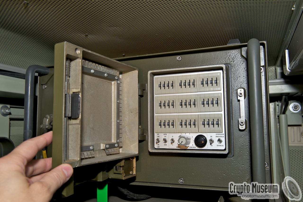
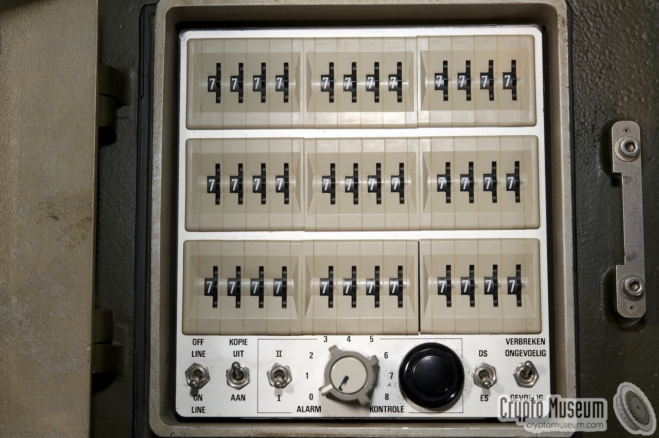
The cryptographic KEY is set by means of 36 thumbwheel selectors, that are located
behind the locked TEMPEST-proof door at the right. Move the mouse over the image
below to reveal which settings and controls are located behind the door.
Behind the heavy door are the key settings, which comprises 36 thumbwheel
selectors, each of which can be set between 0 and 9. Note however, that only
the settings 0-7 are relevant (3 bits). Setting 8 is equal to setting 0, and
setting 9 is equal to setting 1. By convention, all
switches must be set to 7 when the device is not in use.
The key settings compartment also holds configuration selectors, plus a
set of ALARM controls for testing the individual sub-circuits.
Once the key has been set, the Ecolex X is entirely controlled from the
remote control unit (Dutch: Afstandsbedieningskast, or ABK), which is
connected to the main unit (VOT) by means of a thick cable with 32-pin
connectors at either end. This cable carries the data signals as well as
the 230V mains. A Siemens T-100 teleprinter
is connected to the terminals at the top right, and is powered from the
mains socket at the left. The front half of the ABK holds the tape reader
and controls.
The five brightly coloured indicators are labelled in Dutch. The diagram
above shows the English translation. Inside each of the coloured caps is
a light bulb. Furthermore, the rightmost four are also push-buttons.
They can be pressed to enter a certain state or MODE of the device.
|
|
The following versions are known:
|
|
|
Prototype series
UA-8040/00
|
|
|
The initial version of the Ecolex X was designed with circuit blocks
from ELCOMA — Philips' component division. These circuit blocks are very similar
to the FLYBALL modules used by the NSA in devices
like the KW-7 cipher machine.
Very few machines of this type were made – perhaps five to ten – before it was
decided to redesign the device with modern flatpack ICs.
The machine shown in the image on the right has serial number 005.
|
|
|
|
|
Intermediate version
UA-8040/01
|
|
|
Assuming that the numbering scheme used for the different versions
of the Ecolex X is contiguous, there must have been an UA-8040/01
variant. It is likely though, that this was just an engineering version
for evaluation purposes, that was never taken into production.
It is unlikely that there are any surviving specimen of this version.
|
|
|
|
|
Production version
UA-8040/02
|
|
|
Once the initial version (UA-8040/00) was
ready for production, it was decided to do a complete redesign
in order to replace the ELCOMA circuit blocks of the
original design by flatpack ICs.
As a result, the introduction of the machine was delayed significantly,
and all TEMPEST tests had to be carried out again.
The new version, designated UA-8040/02, was introduced in 1972
and a total of 338 units were manufactured.
This version is fully compatible with the UA-8040/00.
|
|
|
The diagram below shows the most basic setup of the Ecolex X. The device
consists of two units: the actual cipher machine (VOT) and a remote
control unit (ABK). Only the VOT is powered from the mains. The
ABK and the Siemens T-100 teleprinter
at the left, ar both powered from the VOT.
In most cases, a TH-3676 FSK modem
(or similar) is needed for connection to the telex line.
When the Ecolex X is connected to a radio set, such as the
Philips RT-3600, an additional radio adapter
is needed, such as the Telefunken TH-4179,
shown in the diagram below at the bottom right. The adapter is connected
between the handset and the radio. It takes
over the function of the push-to-talk (PTT) switch, allowing the Ecolex X
to switch between transmit and receive.
When a later version of the FSK modem (TH-3676B) is used instead of the
TH-3676 shown here, the TH-4179 radio adapter is not needed as it has
an integrated PTT feature. The TH-7376B was used for example with
the SSB radio [G]. A more detailed wiring diagram can be found here.
|
|
|
Cipher unit (VOT)
UA-8040
|
|
|
This is the actual encryption/decryption device
(Dutch: Versleutel-Ontsleutel Toestel (VOT)).
It is powered from the mains and forms the central hub of
the system. The heavy hinged door at the right gives access to
the key setting selectors.
The device is connected to the mains and the telex line, and is
controlled from the remote control unit (ABK, see blow).
|
|
|
|
|
Remote control unit (ABK)
UA-8041
|
|
|
The Ecolex X is controlled from a remote control unit (RCU)
(Dutch: Afstandsbedieningskast (ABK)) that also contains
a tape reader. The ABK is connected to the main unit by means
an 32-pin cable that also carries the mains voltage.
The local teleprinter – in most cases a Siemens T-100 –
was connected to and powered by the ABK. When the ABK was
in transit, the control panel was protected by a metal cover. When the
unit was in use, the metal cover was
stowed on top of the accessory box.
|
|
|
All accessories for the Ecolex X are stowed in the metal container
shown in the image on the right (here shown without the top lid).
Inside the container are several cable assemblies (see below) and a
box with spare parts.
The accessory box consists of two metal shells. When it is
closed, the transport cover
of the ABK can be stowed on top of it.
|
|
|
|
|
Interconnection cable
UA-8042
|
|
|
Cable assembly VOT/ABK (UA-8042) is needed to interconnect the
two main components:
The cable carries the data signals to and from the tape reader and
the front panel controls, but also the 230V AC mains.
|
|
|
|
|
Mains power cable
UA-8043
|
|
|
|
|
Special line cable
UA-8050
|
|
|
This line cable (VOT/SRV) is nearly identical to the one above,
but has two additional wires and can be used to control the push-to-talk
(PTT) of the attached radio. In practice, this was often the
Philips RT-3600 radio.
The two additional wires are connected either to the TH-3676B modem,
the TH-4179 radio adapter or an external send/receive switch box.
➤ More information
|
|
|
Inside the lid of the accessory container is a
grey plastic box with spare lamps and fuses.
The box is retained by a spring steel clip
that is part of the case lid. These are the only parts that may be
swapped by 1st and 2nd echelon repair.
For 3rd echelon repairs, further spare parts were available, such as
fuse holders, switches and coloured indicator caps.
|
|
|
|
|
Line terminator with modem
TH-3676
|
|
|
For connection of the Ecolex X to a telecom line or to a radio, the
teleprinter connection device (TCD)
shown in the image on the right was used.
The local teleprinter was connected – via the Ecolex X – to this
device, in 4-wire configuration. The device was then connected, also in
4-wire configuration, to the radio.
➤ More information
|
|
|
When connecting the Ecolex X to a simplex two-way radio,
via the TH-3776 modem (above), the additional
TH-4179 radio adapter shown here
is required. It allows the Ecolex X to switch between
transmission and reception by taking over the PTT function
of the radio and its handset.
When the TH-3676B modem is used (instead of the TH-3676(A)),
the TH-4179 is not required.
➤ More information
|
|
|
The Ecolex X was used in combination with a
Siemens T-100 teletypewriter (teleprinter)
that was connected to (and powered by) the remote control unit (ABK).
It came in two colours (grey or beige) and acted as an input/output device.
Two versions were available: TT-4230, with tape puncher, and TT-4231,
with a tape puncher at the left and a reader at the right.
The device shown in the image on the right is of this type.
➤ More information
|
|
|
When the Ecolex X was used in a moble environment, it was often connected
to the Philips RT-3600 VHF/FM radio shown in the
image on the right. Depending on the version of this radio, it allowed
secure line-of-sight (LOS) operation up to a distance of 30 km.
The RT-3600 has two U-229 receptacles
at the far right for connection of a handset. Note that this connector uses a
non-standard pinout.
➤ More information
|
|
|
|
Development of the Ecolex X started in 1965, in a move to depart from
One-Time Tape (OTT) cipher machines, on to self-permuting systems.
As it soon became clear that its development would take at least five
years, it was decided to introduce Tarolex as a gap-fill solution.
|
Tarolex was largely based on the
Tapeless Rotorless On-Line
encryptor (TROL) that Philips had developed for a NATO
evaluation in 1962, but NATO had chosen the
BID/610 (ALVIS) instead.
It consisted of an external key generator that was connected
to a modified Ecolex IV one-time tape (OTT) cipher machine.
The key generator effectively replaced the rearmost tape reader of the
Ecolex IV. The KEY was set by means of a short piece
of punched paper tape that was
installed in a static tape reader
behind a door.
Tarolex became the first Dutch self-permuting cipher machine.
As it was based on TROL,
it could be developed in less than a year, which is incredibly fast
for a top-level cipher machine.
|
|
|
|
Tarolex development was started in 1966 and went on
in parallel with the Ecolex X development. It was
rolled out in 1967 and a total of 151 machines were delivered to the Dutch Army.
In addition, the same number of existing Ecolex IV machines were
modified for connection to Tarolex.
|
With the rapid introduction of Tarolex, Philips had bought
itself more time for development of the Ecolex X, which
turned out to be an insightful decision. There were many
hurdles that had to be taken, including a delayed order, ambiguous
specifications and TEMPEST problems.
The machine was initially built with
ELCOMA standard hybrids (circuit blocks),
but was later redesigned with flat-pack ICs [5]. This caused
significant changes to the construction [2].
In addition to unwanted emanations (TEMPEST), the machine also
had to withstand several physical tests, such as
shock and water resistance.
|
|
|
|
The image above was taken at the production site at Schouwbroekseweg
in Eindhoven in the early 1970s, and shows how the device was soak tested [1].
Finally, after a series of additional developments and modifications,
the machine was approved and rolled out.
In total, 388 machines were built, the majority of which went to the Dutch Army,
where they gradually replaced the Tarolex machines.
A small number of machines were provided to the
Dutch Foreign Office [2].
Ecolex X was approved for use in NATO
context for messages at the highest level of secrecy.
|
|
Ecolex X is suitable for offline and online use, via telephone lines,
as well as over HF, VHF or UHF radio.
When used in online mode, the built-in key generator produces a
constant key stream – even when the operator is not typing any text –
so that an eavesdropper cannot determine the start and end of a
message. This principle is known as Traffic Flow Security (TFS).
Ecolex X was intended for stationary use, but could also be
used in a mobile environment, as shown below.
|
|
|
Mobile secure HF/VHF setup
|
|
|
The image on the right shows a similar setup at the back of a DAF YA-126
truck, but in this case a SSB HF transceiver is placed under the table at
the left, whilst the Ecolex X main unit is placed on a shelf at the top left.
To the left of the ABK is a modified TH-3676B modem, which also
takes over the role of the TH-4179 radio adapter.
This truck is also fitted with an RT-3600 VHF radio
which is just visible at the left edge of the picture.
Image taken in 2011 at the Military Communication Museum of Mathieu Driessen
(ON8PO) in Lanaken (Belgium).
|
|
|
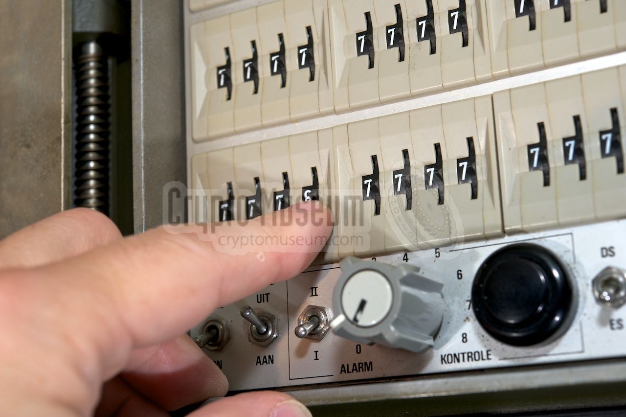
The Ecolex X has an advanced built-in ALARM circuit that allows 14
internal functions (cards) to be tested without disassembling the unit.
The ALARM functions are operated with the middle three knobs in the
key settings compartment (marked ALARM KONTROLE). The rotory switch
at the centre (0-8) is used to select one of eight tests. In addition,
the I/II switch allows a second bank of tests to be selected.
This offers another 6 checks (1 to 6 — 7 and 8 are unused).
Any setting other than '0' enables a test. It introduces a fault in
one of the plug-in cards inside the Ecolex X. This causes the yellow
indicator at the front of the remote control unit (ABK) to be lit.
Now press the black push button to the right of the selector.
The yellow lamp should now go off. Now release the black button and
the yellow lamp should come on again. If this is the case, the test
has been executed successfully. Now repeat this for the other 13 tests.
For full details about each test, please refer to the 1st/2nd
Echelon Technical Manual [F].
|
The interior of the main unit can be accessed by releasing 8 Allen screws
around the edges of the front panel, after which the front panel with all
building blocks can be extracted from the case shell. All parts are mounted
to the front panel by means of retaining clips around the edges.
The image below shows the extracted interior, with the front panel facing
down. The largest part is occupied by a stainless steel card holder
with 27 plug-in cards. The rightmost eight cards (marked 'A') are known
as the wheels and form the key generator.
A full list of plug-in cards can be found here.
Detailed circuit diagrams can be found in the 5th echelon documentation [H].
Plug-in cards can be extracted from the card holder after
releasing the horizontal locking bar.
Furthermore, the entire card holder can be taken off by pushing the
release brackets at either side of the assembly towards to the front panel.
This gives access to the remaining parts:
The image above shows the front panel assembly after removing the
card holder. Each of the remaining units — the transformer and the
two filter units — is held in place by means of retaining clips.
They are connected to the card holder by means of several (arrays of)
connectors.
The modular design allows for quick repairs by 3rd echelon technicians,
simply by swapping modules and/or cards, whilst component level repair is
left to 4th and 5th echelon engineers.
|
|
|
Remote control unit (ABK)
|
|
|
The construction of the remote control unit (ABK) is very similar
to that of the VOT, except that in this case all internal parts are
mounted to the top panel. Loosen the four screws in the corners of the
top panel to extract the entire interior from the case shell, as shown
in the image below.
The ABK comprises three functional blocks: the tape reader (right)
and two filter units (left) each of which protrudes the front panel
and is held in place by means of retaining clips. The tape unit is
unshielded as it has no direct connections to the outside world.
It can be removed in its entirety by
releasing 4 retaining clips. This part also holds
the five coloured push-buttons.
|
| Card | Function |
| A | Key generator (nine identical cards) |
| B | Timebase (for key generator) |
| C | Mixer |
| D | Noise generator (for message key generator) |
| E | Message key generator |
| F | Crystal oscillator, Baud rate setting |
| G | Asynchronous timebase |
| H | Synchronous timebase |
| J | Register A, Register C, Letters/Figures |
| K | Register B, Program recognition |
| L | Function counter, not synchronised alarm |
| M | Function counter control, Send/receive switch, indicator lights |
| N | Teleprinter circuits |
| P | Break-in, Reset, Tape reader magnet control |
| Q | Tape reader data processing |
| R | Who-Are-You (WRU) recognition, Baudrate setting |
| S | 6 sec delay for simplex radio traffic |
| T | +6V stabiliser, +12V and +60V rectifiers |
| U | Smoothing capacitors +6V, +12V, +60V |
| V | Tape reader control, tape sensing, teleprinter input |
| W | Indicator control, key buffering (controls) |
| X | Line filter |
| XX | Filter, Relay for radio TX/RX |
| Y | Filter for remote control unit (ABK) |
| Z | Teleprinter filter |
|
The Ecolex X featured on this page, has not yet been tested,
and restoration of the machine and its accessories therefore hasn't
started yet.
|
Since development of the Ecolex X took a rather long time, it was decided
that a separate key stream generator would be developed as a gap-fill
solution. In 1966/67, the so-called Tarolex 19" was developed
for use with a modified Ecolex IV machine. Like the
Ecolex X, Tarolex was based on the earlier
TROL developments.
Approx. 150 Tarolex units were
delivered to the Dutch Army and an equal number of existing
Ecolex IV machines was modified for them
[2].
➤ More about Tarolex
|
|
|
Following the success of the Ecolex X, Philips developed its successor,
Ecolex 20, 1
in the mid-1980s. Although the design was completed
and was even listed in Jane's Military Communications of 1986, it was not
taken into production.
It did not meet the requirements of the era and development of the all-new
ZODIAC integrated communication
system was already underway.
➤ More information
|
|
|
-
Note the use of Arabic numerals.
|
|
|
With RT-3600 VHF/FM radio
|
|
|
Below is the same setup, but with an additional TX/RX switch added at the
bottom right. This switch controls the push-to-talk (PTT) line of the radio and
allows the automatic PTT-contact from the Ecolex X to be overruled.
It is likely that this was an aftermarket upgrade (1975) as the switch
is not painted green and does not have a NATO stock number (NSN) or any other
designator. It is only
shown in Instruction Card IK11-529 [E] and is visible in
this photograph.
|
|
The mains power input is at the top left of the front panel of the Ecolex X.
Below is the pinout of the 10-6P connector, when looking into it. This connector
accepts a 10-6S cable part. 220V AC mains power is applied to pins A and D.
Ground should be connected to pin B. When a shielded cable is used (needed
for TEMPEST reasons) the shield to be connected to pins
C, E and F.
|
PWR 220V AC (1) GND Ground GND Shield PWR 220V AC (2) GND Shield GND Shield
|
|
The wiring of the individual connectors of the Ecolex X is specified in the
4rd/5th Echelon Technical Manual [H pp. 5-1 to 5-5].
For the other connectors, check the relevant pages on this website where
the corresponding devices are described.
|
Device Telex encryption device with Trafic Flow Security (TFS) Purpose Military telex encryption Name Ecolex X Model UA-8112/00 Designator KL/TGA-3572 Manufacturer Philips Usfa Country Netherlands Development 1965-1972 Years 1972-1992 NSN 5810-17-030-9001 Predecessor Ecolex IV, Tarolex Successor Ecolex 20 Teleprinter Siemens T-100, single current 30 — 60 mA (set by 3rd echelon) Line Single current (20 mA or 40 mA), double current (± 12.5 mA) Speed 50, 70, 100, 150, 200, 300 baud (set by 3rd echelon) Power Mains 115V, 127V, 220V (switch selectable) Parts Main unit, Remote control unit, Accessory kit Quantity 388
|
Device Self-permuting cipher machine Purpose Secure online military telegraphy with traffic flow security Name VOT Model UA-8040/02 Designator KL/TGA-3572(A) Manufacturer Philips Usfa Country Netherlands NSN 5810-17-036-7028 Keys 836 (108 bits) Dimensions 490 × 310 × 300 mm Weight 33.5 kg
|
Device Remote control unit with punched paper tape reader Purpose Control of Ecolex X (UA-8040), Tape reader, Interface to T-100 teleprinter Name ABK, Afstandsbedieningskast (remote control unit) Model UK-8041 Designator KL/TGA-3572(B) Manufacturer Philips Usfa Country Netherlands NSN 5810-17-036-7029 Line current 30 — 60 mA, typically 40 mA Dimensions 450 × 250 × 260 mm Weight 20.5 kg
|
Device Metal case with accessories and spare parts Purpose Wiring Ecolex X, ABK, teleprinter and line (or radio) Name Koffer, toebehoren (Case, accessories) Model UA-8048/01 Designator KL/TGA-3572(C) Manufacturer Philips Usfa Country Netherlands NSN 5810-17-036-7034 Dimensions 450 × 250 × 120 mm Weight 7 kg Parts see below
|
- Ecolex X
- Ecolex 10
- UA-8112/00
- UA-8040/02 + UA-8041
- KL/TGA-3572
- 5810-17-030-9001
- VOT + ABK
|
005 VOT Crypto Museum, Netherlands (prototype) 199 ABK Royal Signals Corps Historical Collection, Netherlands ? VOT Royal Signals Corps Historical Collection, Netherlands 275 ABK Crypto Museum, Netherlands 333 VOT Military Communication Museum, Belgium 1 ? ABK Military Communication Museum, Belgium 1 345 VOT Crypto Museum, Netherlands
|
 |
| Description | Dutch Army | Model | Philips | NSN |
|
|
| Complete set | KL/TGA-3572 | UA-8112/00 | - | 5810-17-030-9001 |
| |
|
|
Complete set
UA-8112/00
|
|
|
|
|
| Ecolex X (VOT) | KL/TGA-3572(A) | UA-8040/02 | 4322 081 39270 | 5810-17-036-7028 |
| Remote (ABK) | KL/TGA-3572(B) | UA-8041/02 | 4322 081 39280 | 5810-17-036-7029 |
| Accessories | KL/TGA-3572(C) | UA-8048/01 | 4322 081 38600 | 5810-17-036-7034 |
| |
|
|
Acessories
UA-8048/01
|
|
|
|
|
| Cable VOT/ABK | | UA-8042/01 | 4322 081 39520 | 5995-17-036-7030 |
| Cable VOT/NET | (mains) | UA-8043/02 | 4322 081 75470 | 5995-17-039-3525 |
| Cable VOT/KL-line | | UA-8044/01 | 4322 081 39540 | 5995-17-036-7032 |
| Cable VOT/SRV | | UA-8050/00 | 4322 081 39550 | 5995-17-036-7033 |
| Spares (see below) | | UA-8069/00 | 4322 081 39510 | 5810-17-036-7036 |
| |
|
|
Spares
UA-8069/00
|
|
|
|
|
| Lamp, 14V/80mA, BA9S base | 2422 533 00011 | 6240-00-941-8488 |
| Fuse, 30 × 6 mm glass, 0.75A/250V, slow | 2422 086 10185 | 5920-00-846-5725 |
| Fuse, 30 × 6 mm glass, 1A/250V, slow | 2422 086 01063 | 5920-00-850-6091 |
| Fuse, 20 × 5 mm glass, 2A/250V, slow | 2422 086 01031 | 5920-12-124-7829 |
| Fuse, 30 × 6 mm glass, 4A/250V, slow | 2422 086 00075 | 5920-00-174-0836 |
| |
|
|
Additional
|
|
|
|
|
|
Teleprinter 1
|
TT-4230
|
T-100
|
-
|
5815-17-035-7786
|
|
Teleprinter 1
|
TT-4231
|
T-100
|
-
|
5815-17-035-7787
|
|
FSK Modem
|
TH-3676
|
-
|
-
|
5805-17-036-0253
|
|
Radio adapter
|
TH-4179
|
-
|
-
|
5805-17-034-8023
|
|
|
-
Only one T-100 teleprinter needed.
Both types have a built-in tape puncher. TT-4231 also hs a tape reader.
|
- List of items for KL/TGA-3572 (Dutch)
CM-300672. Dutch Army, 1 February 1973.
- IK11-519/3, Instruction card 3 (Dutch)
Describes connection of the TH-3676 to 2- or 4-wire line.
CM-300667. Dutch Army, 27 September 1976.
- IK11-519/4, Instruction card 4 (Dutch) 1
Describes connection of the TH-3676 to an SSB radio.
CM-300668. Dutch Army, 9 April 1979.
Replaces IK11-519/4 of 27 September 1976.
- IK 11-519/5, Instruction card 5 (Dutch) 2
Connecting TH-3676 or TH-3676A to teleprinter and/or Ecolex X.
Dutch Army, 22 September 1980.
- IK11-529, Instructiekaart voor de bediening van FM Radio-Telexinstallatie KL/MRC-2238
Instruction card for the operation of FM RTTY installation KL/MRC-2238 (Dutch).
Dutch Army, 25 June 1975, 2nd edition.
- Ecolex-X Technical Manual 1/2 (Dutch)
Technische handleiding vercijfer- ontcijferuitrusting KL-TGA-3572.
1e en 2e echelons bediening en onderhoud.
CM-300669. 1/2TH11-959. Dutch Army, 26 January 1973.
- Ecolex-X Technical Manual 3 (Dutch)
Vercijfer- en ontcijferuitrusting KL/TGA-3572.
3e echelons technische beschrijving en onderhoud.
CM-303239. 3TH11-959. Dutch Army, 12 September 1973.
- Ecolex-X Technical Manual 4/5 Wiring Diagrams (Dutch)
Vercijfer- en ontcijferuitrusting KL/TGA-3572.
4e en 5e echelons onderhoud. Bedradings- en montagegegevens.
CM-300287. 4/5TH11-959/2. Dutch Army, 5 October 1976.
- Ecolex X KL/TGA-3572, Training Instructions: 23-10A
Verbindingsdienst (Signals Corps), Lesstencil (Dutch).
CM-302674. Dutch Army, August 1985.
|
|
-
Document kindly provided by Bart Wessel.
-
Document kindly provided by Kees Raaymakers.
|
|
|
|
Any links shown in red are currently unavailable.
If you like the information on this website, why not make a donation?
© Crypto Museum. Created: Sunday 16 June 2013. Last changed: Wednesday, 01 April 2026 - 23:28 CET.
|
|

|
|
|
| | |


![Ecolex-X machine under soak test. Photograph courtesy Philips Usfa [1].](img/301322/000/full.jpg)


