|
|
|
|
|

|
|
CIA BND RS-49 RR-49 →
The device is similar in controls and operation to the
RT-3 transmitter
of the RS-1 spy radio set
and the RT-6
of the RS-6 radio set, but is much
smaller and weigths less, due to the fact that it is fully transistorised.
The device measures just 137 x 102 x 40 mm and weighs just
700 grams.
In most cases the transmitter was operated by means of
HC-6/U shaped crystals,
as shown in the image on the right. It was also possible
to use an external Variable Frequency Oscillator (VFO) or even a
digital synthesizer, by using the 3-pin socket to the left of the
crystal socket.
|
|
|
|
The device is suitable for transmission of CW signals only
(morse code). Although it is possible
to connect a regular morse key, the unit was usually connected to
a KE-8 keyer
that allowed pre-recorded messages to be transmitted
at very high speed. This significantly reduced the on-air time
and, hence, the chance of being discovered by means of
Radio DIrection Finding (RDF).
|
HELP REQUIRED —
At present, no further information about the RT-49 transmitter is
available. We are looking for the full operating instructions and
for the circuit diagram. We are also looking for the
original RP-49 power supply unit. If you can provide any of these,
or if you have additional information, please contact us.
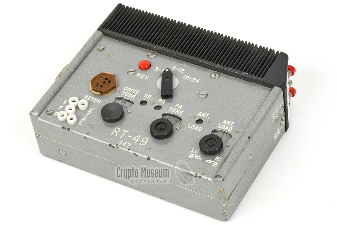
The image below provides on overview of the controls and connections
of the RT-49 transmitter. Power should be provided by the accompanying
RP-49 power supply unit (PSU) that must be attached and latched
to the left side of the transmitter.
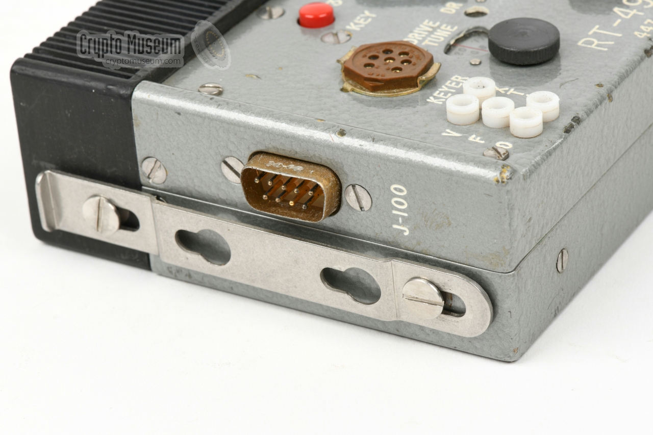
The DB9 connector
at the left side mates with
a connector on the side of the PSU.
At the rear right – integrated with the black heat sink – are
spring-loaded terminals
for connection of the antenna and ground wires, and the receiver.
When operating the device, a suitable crystal should be installed in
the crystal socket at the bottom left and the band selector should be
set to the corresponding frequency band. After connecting a
suitable antenna, the red button marked KEY should be pressed,
whilst the three tuning dials are adjusted for maximum signal,
using the indicator lights to find the maximum.
The unit is now ready for use. Although it is possible to connect
a regular morse key to the KEYER socket (pins D and F), the transmitter
was normally used with a KE-8 keyer,
to allow high-speed transmission of a pre-recorded message.
This was done to reduce the risk of being discovered.
|
|
At the centre of the left side of the transmitter is a 9-pin male DE-9 connector
that mates with the female DE-9 connector on the RP-49 PSU. Below is the
pinout when looking into the male connector on the transmitter [1].
|
- Ground Red +42V DC (from PSU) - not connected Yellow 0V DC to keyer (isolated) Green –12V DC to keyer (isolated) - not connected - Receiver antenna - not connected White/orange Unknown 1
|
|
-
Connector to centre pin of VFO connector.
|
|
Below is the pinout of the KEYER socket of the transmitter,
when looking into the socket.
The layout of this connector is identical to that of the socket on the
KE-8 keyer, but note that there are
additional lines that are not used
by the KE-8.
Also note that the 12V DC power supply for the keyer is
isolated (pins C and H). This is necessary as the keyer uses negative
logic.
|
Black RF Ground White/red T/R relay control 1,2 Green -12V DC power supply (to keyer) Blue Keyed signal (from keyer) Red +42V DC 2 - Signal Ground Yellow 0V power supply (to keyer)
|
|
Year 1965 User CIA Purpose Agent communication Frequency 3 - 24 MHz Band 3 Modulation CW Circuits Oscillator/doubler, PA Power 42V DC, 1.4A Output 15W Dimensions 137 x 102 x 40 mm Weight 700 grams
|
White ● 3 - 6 MHz Red ● 6 - 12 MHz Green ● 12 - 24 MHz
|
- RP-49 power supply unit
- Morse key
|
-
Approved for release by CIA on 23 April 2014.
|
- Trip Report - Development f the RT-49 and RP/A-49
CIA Memorandum, 28 February 1963
- Chief, OC-OS to Chairman, Equipment Board, Equipment Procurement
CIA Memorandum, 2 January 1964
- Equipment Board staff meeting, Agenda
CIA, 9 January 1964
- CIA Equipment Board staff meeting, minutes
9 January 1964
- Trip Report - RT-49/RP-49
24 November 1964
- Trip Report - RT-49/RP-49
22 December 1964
- Trip Report - RR-49
22 December 1964
- Inspection Report No. 1 - AN/B-62
CIA Memorandum, 11 May 1966
- Inspection Report No. 5 - RT-49/RP-49
17 June 1966
- Inspection Report No. 6 - RT-49
CIA Memorandum, 21 June 1966
- Inspection Report No. 2 - AN/B-62
CIA Memorandum, 24 June 1966
- Equipment Board Meeting, Agenda
CIA, 8 November 1967
- Long-Range HF Communications Equipment
7 April 1969
|
|
|
|
Any links shown in red are currently unavailable.
If you like the information on this website, why not make a donation?
© Crypto Museum. Created: Thursday 05 November 2020. Last changed: Wednesday, 05 November 2025 - 12:10 CET.
|
 |

|
|
|


![Secret CIA polaroid photograph of RS-49 agent radio [3]](img/rs49_1_thumb.jpg "image # rs49_1_large.jpg")
![Secret CIA polaroid photograph of RS-49 agent radio [3]](img/rs49_2_thumb.jpg "image # rs49_2_large.jpg")


![Secret CIA polaroid photograph of RS-49 agent radio [3]](img/rs49_1_large.jpg)
![Secret CIA polaroid photograph of RS-49 agent radio [3]](img/rs49_2_large.jpg)