|
|
|
|
|

|
Radio Direction Finding
Over the years, many techniques
have been developed for locating the
position of a transmitter. The most simple but nevertheless effective method,
is to use a receiver or a field strength meter
in combination with an adjustable attenuator. A slightly better
method is to use a directional antenna to (manually) find the direction
in which the signal is the strongest (or the weakest).
|
|
|
DF equipment on this website
|
|
|
|
The following basic direction finding techniques are described below:
|
The most common method for locating the position of a transmitter during
World War II (WWII)
and in the early years of the Cold War,
was by using two or more mobile reception stations with directional
antennas. As soon
as the transmission started, each mobile station would try to find the
angle at which the signal strength was the highest, 1 and draw it as a line
on the city map.
As a directional antenna is not perfect, and because of reflections of the
radio waves against buildings etc. the angle has a certain tolerance.
The drawing above illustrates how this works, when two mobile Radio Direction
Finding (RDF) stations (A and B) have determined a bearing on a rogue
transmitter (T). Because of the triangle A-B-T, this method is known as
triangulation.
In the example above, there is still an uncertainty of several houses.
Furthermore, the method does not work when the transmitter is located exactly
in between the two reception stations. This could be solved by using three or
more RDF stations at strategic positions around the city. Once the position
of the transmitter had roughly been determined, the interceptors would move
closer towards the target, in order to narrow down the angle of tolerance.
Once the average position was known, the interceptors would generally use
field-strength measurement for the final stage.
From the above example it will be evident how dangerous it is to operate a
rogue transmitter at wartime. For this reason, agents often changed
the location of their transmitter and tried to keep their transmissions
as short as possible. This was done be minimising the length of a message,
and by sending the message as a high-speed burst, by means of a
so-called burst transmitter.
|
|
-
In practice it is often better to determine the angle of the lowest
signal strength, as it is easier to find and has a smaller tolerance.
The direction to the transmitter in then 90° higher or lower.
|
|
|
1. Field strength mesasurement
|
|
|
|
One of the simplest and most effective ways to find a rogue transmitter,
is to use a field-strengh meter with an adjustable attenuator.
An interceptor with a mobile Radio Direction Finding (RDF) station would
first drive down a main road to see whether the signal becomes stronger
or weaker.
|
He would then adjust his plan. When getting closer to the
transmitter, the attenuation would be increased, so that the field-strength
indicator still produces a usable reading on its scale. In practice, an
experienced interceptor can usually determine the position in less
than 30 minutes.
Field-strength measurement is still widely used today,
often used in combination with other
RDF methods – such as Triangulation and
Automatic Direction Finding (ADF) – especially during the final stage
of the job, to find the exact building from which the
rogue transmitter is operated.
|
|
|
|
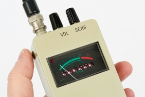
Field-strength (FS) meters are relatively simple instruments that can be
made with just a couple of components. Yet they are very effective,
especially in close proximity of the transmitter. They can be
selective or non-selective, with the former being insensitive to
strong (unwanted) nearby radio signals. The image above shows a non-selective
handheld FS-meter with built-in frequency counter,
that was used by the Dutch Radio Monitoring Service (RCD)
during the 1980s and 90s.
|
|
|
Examples of field-strength meters
|
|
|
|
|
2. Manual direction finding
|
|
|
|
The basic form of true direction finding, is by using a (somewhat)
directional antenna, such as a dipole, open loop, window, Adcock, Yagi
or Log Periodic. By connecting the antenna to a receiver and turning it
around, the angle of maximum or minimum signal strength can be determined.
|
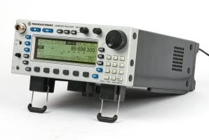
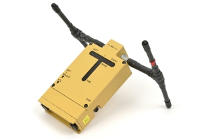
In case of a portable receiver and antenna, the interceptor could walk towards
the transmitter until it is found. A good example of a modern manual direction
finder, is the Rohde & Schwarz PR-100 in combination with the
HE-300 portable antenna, as shown in the image on the right.
Older systems include the DAG-1,
which is of WWII vintage. It was designed for use by the US Navy, probably for
navigation purposes, but was also used after the war to find clandestine
radio stations (pirates) and even illegal radio stations operated by East European
(Cold War) agents.
|
|
|
|
The DAG-1 uses a magnetic loop antenna, which is sensitive
to the magenetic field of the radio wave only. Like other simple directional
antennas (dipole, Adcock), it is symmetric and suffers from an 180° ambiguity.
This means that it can not tell the difference between front and back.
|
A significant improvement was the Goniometer, also known as Bellini-Tosi or
B-T Goniometer, invented in 1907 by Ettore Bellini and Alessandro Tosi, and
described in US Patent 943,960. It uses two loop antennas,
typically long wires wound around a wooden frame, at perpendicular angles (i.e.
90° apart). The wires of these two loops are connected to the static windings
of the goniometer (stators), whilst a single rotor winding is connected to the
input of the receiver.
|
| |
Bellini-Tosi Goniometer · 1907
|
This invention allowed the user to hunt for signals by rotating the
goniometer, without actually moving the (large) antenna. The drawback
of this method is the 180° ambiguity of the antenna plus the sensitivity
to ground and ionospheric reflections, especially on higher frequencies.
|
The latter was solved by using four vertical monopole
Adcock antennas, invented in 1918 by Frank Adcock
and described in UK Patent 130,490.
It consists of two pairs of cross-connected vertical dipoles.
Like the Bellini-Tosi window antennas, it suffers
from the 180° ambiguity. Both the B-T Goniometer and the
Adcock antenna were later used with
Automatic Direction Finders.
|
|
|
Example of manual direction finders
|
|
|
|
|
3. Automatic direction finders
|
|
|
|
In order to understand the principle behind the various techniques
that are used for automatic direction finders (ADF), it may be useful
to examine the differences between them. Generally speaking, the following
techniques are available for automatic radio direction finding:
|
High Frequency Direction Finding,
commonly abbreviated as HF/DF or
referred to by its nickname huff-duff,
was one of the first methods
of automatic direction finding. It is based on a system developed in 1926
by Robert Watson-Watt for locating lightning strikes, and
displays the signal from two loop antennas on an
oscilloscope, so that the angle of incidence can be read instantly.
The system was widely used during WWII, for example during the
Battle of Britain for guiding British fighers to their destination,
and during the Battle of the Atlantic against German U-boats.
The signals from the two loop antennas are processed by two highly
identical receivers, and fed to the X and Y inputs of an oscilloscope.
A line will then be displayed at the angle of incidence.
Watson-Watt also solved the 180° ambiguity problem, by adding a so-called
sense antenna to one side of a loop, to that the opposite side would be
less visible on the oscilloscope. This was later improved by adding a
third (highly identical) receiver to the setup, and using the signal from
the sense antenna to drive the Z-axis (i.e. the beam luminance) of the
oscilloscope. The concept is also known as
Cathode-Ray Direction Finding (CRDF), Twin-Path DF and Watson-Watt DF.
➤ More about HF/DF
➤ Read Arthur Bauer's paper about HF/DF
|
|
|
Examples of Watson-Watt direction finders
|
|
|
|
|
|
|
Adcock is not a direction finding principle as such, but merely an antenna
design, invented in 1918 by Lt. Frank Adcock, that was used in combination
with the Watson-Watt principle.
It is officially known as Adcock/Watson-Watt, but is commonly
referred to simply as Adcock DF.
An Adcock antenna consists of spaced vertical open antennas, which in
principle respond only to the vertical component of polarization of an
incident wavefront. A two-element Adcock antenna is equivalent to a
frame antenna of which the top horizontal arm is removed. The two remaining
vertical elements are spaced no more than λ/4.
In a crossed Adcock antenna, two vertical element pairs are used
in a mutually ortogonal arrangement, in such a way that the first pair produces
the sin φ and the second one the cos φ
of the angle of incidence (φ).
OAR uses this arrangement:
One pair is used to determine the west-east component (W/E) and another
one to determine the north-south component (N/S). The signals from these
antennas are used to control the X and Y deflection of the CRT. A central
whip (here shown in red) acts as the reference antenna (R).
It is used for resolving the 180° ambiguity. The latter is performed
automatically by special circuits.
The circuit diagram above shows how the two antenna-pairs are connected.
Each element (X1) is cross-connected to the diagonally opposite one (X2).
The resulting pair is connected to the receiver via a transformer (X).
The second pair (Y1 and Y2) is placed at 90° and is also connected to the
receiver via a transformer (Y). This antenna arrangement was invented in 1918
by Frank Adcock, and is described in
British Patent 130,490
[4].
Further information on Wikipedia
[5].
|
|
|
Examples of Adcock direction finders
|
|
|
The Homer principle is commonly used in aviation and consists of two
forward facing directional antennas that are pointing slightly off-center.
By using the antenna radiation patterns and quickly switching between the two antennas,
jumps in signal strength can be measured, except when the transmitter
is dead ahead, in which case the signal strength is equal on both antennas (point P).
The diagram above shows how this works. The two antennas (A) and (B)
have identical radiation patterns, but are facing slightly different directions
of, say, +15° and -15° from the front of the vehicle. When the transmitter is
dead ahead, the signal from both antennas will be equal (A=B) and no jumps
in signal strength are measured. This is the case at point P in the above diagram.
When the signal strength between the two antennas is different
(e.g. when B>A), the jumps in signal level are a measure for the angle
of incidence. This is the case at point Q in the example.
The diagram above shows how the signal strength from
both receivers is used to affect the reading of the indicator in both directions.
In rest (A=B) the meter is pointing upwards (0V).
|
Automatic Bellini-Tosi is an improved variant of the
Bellini-Tosi Goniometer (B-T Goniometer) of 1907,
in which the rotor coil of the goniometer, or
RF Resolver, is not operated by hand but by a servomotor in combination
with a feedback loop from the receiver. Furthermore, the signal from a
sense antenna is injected somewhere in the signal path,
to resolve the inherent 180° ambiguity.
The diagram above illustrates the principle.
By injecting a low-frequency component into the RF signal from the goniometer, and phase-comparing it with the same component in the output
of the receiver, the servo-motor is driven until a signal minimum (null) is
found.
This concept was used for many years in the aviation industry,
and has the advantage over the HF/DF and Adcock based
systems, that it does not require three highly identical receivers,
but just a single one.
|
|
|
|
|
In a Doppler-based direction finding system, the antenna can be imagined as
rotating at constant speed in a horizontal plane as shown in the drawing below.
The circular motion of the antenna (A) induces a sinewave frequency modulation
(fm) in the received signal (fc). This effect is known
as a doppler shift. The phase (φ) of the sinewave modulation
(fm) will be determined by the angle of incidence (α)
of the received signal (fc).
By comparing the phase of the motor driving source and the demodulated signal,
the original angle of incidence of the received signal can be determined.
In reality, the antenna rotation is simulated by electronically commutating
(switching) between a number of discrete antennas that are evenly spread
around the circumference of the circle. In practice, most arrangements
consist of four or eight discrete antennas. In addition, a reference antenna (R) is often
placed at the center of the circle, for reception in the conventional manner.
In that case, the reference signal is used to cancel out voice-induced frequency modulation, so that the phase of the doppler-induced frequency modulation
(fm) can be determined more accurately.
|
|
|
Example of a doppler-based direction finder
|
|
|
|
|
|
|
The Angle of Arrival (AoA) principle, also known as Power of Arrival (PoA),
directly measures the angle of incidence of the intercepted signal,
by observing the amplitude changes of a rotating directional antenna.
By using four or more discrete directional antennas in a circular arrangement,
and switching between them in quick succession, the effect of a rotating
antenna is simulated.
As a directional antenna is used — such as a Yagi, Log-Periodic
or Beverage antenna — a reference antenna is no longer
required as the 180° ambiguity does not exist. This simplifies the design.
Imagine an ideal directional antenna, which rotates at constant speed in
a horizontal plane as illustrated in the diagram above. The antenna
produces a signal with amplitude (A), which is a function of the angle of
rotation (α). When the antenna is facing the transmitter, the
maximum amplitude is obtained (A0). In the opposite direction
(180°), the minimum amplitude is obtained. For an ideal directional
antenna, the amplitude as a function of the angle, is calculated as:
With a non-ideal directional antenna, the pattern will be similar,
although the sinewave will be further away from the X-axis.
The variations in signal strength of the intercepted signal, will
result in a similar fluctuation of the strength of the IF signal
of a receiver (commonly at 10.7 MHz). This can be regarded as
a form of Amplitude Modulation (AM), which looks like this:
By applying this signal to an AM detector and removing the DC
component, the phase of the resulting sinewave can be determined.
By comparing the phase to the forward direction (N), the angle
of incidence can be calculated. This is usually done by means of
a microcontroller.
The above diagram shows the position of the AM envelope when the
transmitter is placed at 45° east from the north. In this case,
the maximum amplitude will occur at 45° from the start.
The same 45° shift can be observed at the zero-crossing points,
which are generally easier to find. By observing the direction
of the tangent at the zero-crossings, the 180° ambiguity
can be avoided.
|
|
|
Example of an AoA direction finder
|
|
|
|
|
3g. Correlative interferometer
|
|
|
A correlative interferometer uses two or (preferably) three highly identical
antennas and receivers, spaced at known distances, plus the signal from a
(4th) reference antenna, and analyses them in a computer system, using advanced
mathematical techniques such as Fast Fourier Transform (FFT).
The phase of the signals is then used to calculate the bearing to the
transmitter. When used from an aircraft with three antennas, it is possible
to calculate both the azimuth and the elevation [8].
The illustration above shows how this works for a system with 3 antennas
placed in a triangle. The antennas are connected to three highly identical
receivers that are tuned in parallel, by means of a common local oscillator (LO) that is controlled by a computer system. The signals of the three
receivers are
converted to the digital domain (i.e. digitised) and then fed
to the computer.
The principles behind the correlative interferometer were first described
in 1961 by C.W. McLeish and N. Burtnyk [8].
One of the first companies to manufacture a commercially available
correlative interferometer in the mid-1980s, was
Watkins-Johnson in Gaithersburg (Maryland, USA) [9].
In 1987 it was improved by David Tong,
and sold by his company Datong Electronics Ltd.
in Leeds (UK), as an alternative to Doppler [10].
The Datong solutions were used by various European law-enforcement and
intelligence agencies until at least the early 2000s, for fixed as wel as
vehicle-based DF, in particular for following people, vehicles and money
by means of tracking beacons.
|
|
|
Example of a correlative interferometer direction finder
|
|
|
|
A Time-of-Arrival (ToA) direction finder is similar to the correlative
interferometer shown above, but uses differences in time between the arrival
of the incident wave front at each of the two or more antennas. By analysing the
signals, it is possible to calculate the bearing to the
transmitter (e.g. a tracking beacon) with an accuracy of 1° or better.
|
|
|
Example of a time-of-arrival direction finder
|
|
|
|
|
Direction finders on this website
|
|
|
|
The following direction finders are described in more detail on this
website. Read the short introductions below and click on
More information, or click the image on the right for further details.
Alternatively, click any of the thumbnails at the top of this page.
|
This small receiver was used during WWII to locate clandestine
transmitters, mainly operated by German agents in and around London.
The unit is housed in a Bakelite enclosure and its lid acts as the
frequency range 'plug-in' as well as the direction-sensitive antenna.
The receiver is commonly known as the GPO-receiver, but its official
name was Tester WL-53400. It was only built in small quantities.
➤ More information
|
|
|
BC-792 – also known as SCR-504 – was a portable covert direction finder,
developed in 1943 and used by the OSS (the predecessor of the CIA) for
finding clandestine transmitters operated by spies during World War II.
The device is concealed as a regular leather travel suitcase, and was also
used during the early part of the Cold War in various European countries.
➤ More information
|
|
|
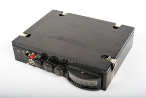
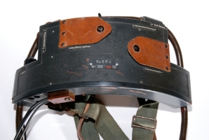
The Gürtelpeiler was probably the first body-worn intercept receiver.
It was used during WWII by the German secret services to locate
clandestine transmitters operating in countries occupied by the Germans.
The valve-based receiver can be concealed under the operator's clothing
with a loop antenna around the neck.
➤ More information
|
|
|
During the Cold War,
the USSR (Russia) developed a series of highly portable
intercept receivers that were deployed in most Warsaw Pact countries.
Such receivers where generally carried around the operator's waist, hidden
under his clothing.
They also developed stationary and mobile intercept radios and other
direction finding equipment.
➤ More information
|
|
|
This German-built portable direction finding receiver was used
in the Netherlands in the early 60s to track down clandestine
radio stations and foreign secret agents. The receiver is housed
in a wooden case, so that the internal window-antenna can be
used. It is operated by a trigger-switch hidden under the carrying
handle.
➤ More information
|
|
|
The PE-484 was a body-wearable miniature direction finder (Kleinstpeilemfänger)
introduced around 1958 by Telefunken in Germany.
It could be hidden inconspicuously under the operator's clothing
and was intended for tracking down clandestine radio stations.
In some countries, the PE-484 was used until the early 1980s.
➤ More information
|
|
|
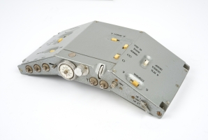
RZ-301 is a rare short-wave direction finder built in Chechoslowakia
around 1948.
It comes with four plug-in modules that can be inserted at the bottom
of the unit. Each plug-in unit covers a specific frequency range.
It was used by the Czech Secret Police (StB)
to track down clandestine
(spy) radio stations
during the Cold War.
➤ More information
|
|
|
|
|
FBA Peiler
Nahfeldausforschungsgerät
|
|
|
This small hand-held direction finder that covers 3 to 145 MHz,
was built by the Austrian Radio Monitoring Service of the ÖPT in 1963,
especially for unobtrusively searching for clandestine radio stations,
such as Cold War spy transmitters.
The receiver is fully transistorized and comes with 15 frequency plug-in
units, nicely packed in a sturdy metal carrying case.
➤ More information
|
|
|
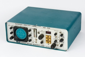
The American company OAR built a wide range of radio direction finders
that were intended as a navigational aid aboard ships. Special versions,
the so-called 9xx-range, were made for locating clandestine radio stations
(pirates).
The image on the right shows the ADF-940 which has a built-in 40-channel
scanner for the 27 MHz citizens band (CB).
➤ More information
|
|
|
|
|
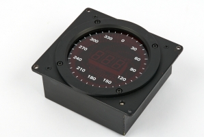
TAIYO direction finder
TD-L1706
|
|
|
TD-L1706 was a direction finder made by the Japanese company TAIYO Musen.
Although it was intended for the maritime industry, it appeared to be
very adequate for finding clandestine transmitters (priates) on land.
The system consists of a main unit, a compass display (shown on the right)
and an flat antenna that could be disguised as the sunroof of a car.
➤ More information
|
|
|
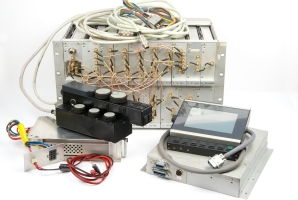
PAN-1000 was a high-end general coverage panoramic receiver, developed by
the Dutch Radar Laboratory (NRP) for the Dutch Radio Monitoring
Service (RCD) in the early 1980s.
The receiver covers a frequency range from 0.1 to 1000 MHz
and could be fitted inside a car. It was intended for locating
clandestine radio stations (pirates).
➤ More information
|
|
|
The EB-200 is the successor to the EB-100. It is a portable receiver
that covers all frequencies between 10 kHz and 3 GHz, with a wide
variety of modulation types: AM, FM, CW, LSB, USB, Pulse and I/Q.
It is one of the first receivers that has
a fully digital IF-stage with DSP technology.
The radio was intended for monitoring of the frequency spectrum and
for locating sources of transmission, including
covert listening devices.
➤ More information
|
|
|
Bird Dog 360XAT is a complete system for vehicle tracking, consisting
of a doppler-based direction finding receiver and compible transmitters,
developed by Audio Intelligence Devices in Florida (USA).
➤ More information
|
|
|
DF-5 is a mobile radio direction finder based on the
correlative interferometer principle, made
by Datong in Leeds (UK).
The device was used by law enforcement agencies as a beacon
tracker when following money transports and suspects.
It was commonly used in combination with a compatible beacon, like the
D-902 or D-903.
➤ More information
|
|
|
This small handheld direction finder was used by law enforcement and
intelligence services for locating nearby tracking beacons and distress
transmitters. The device has two antennas and works on the principle
of Time of Arrival (ToA).
➤ more information
|
|
|
- Wikipedia, Radio direction finder
Retrieved December 2020.
- Wikipedia, Automatic direction finder
Retrieved December 2020.
- Charles J. Murphy, An evaluation of shore-based Radio Direction Finding
US Department of Transport, United States Coast Guard, Office of R&D.
CG-D-28-78. Final Report. September 1978.
- Frank Adcock, British Patent 130,490
Filed 20 August 1918, Issued 7 August 1919.
- Wikipedia, Adcock antenna
Retrieved December 2016.
- Ettore Bellini and Alessandro Tosi, US patent 943,960
Filed 1 October 1907. Issued 21 December 1909.
- Arthur O. Bauer, HF/DF An Allied Weapon against German U-Boats 1939-1945
27 December 2004.
- McLeish & Burtnyk, The Application of the Interferometer to HF Direction Finding
IEE, Vol. 108, Issue 41, September 1961, pp. 495-499, 1961.
- Moell & Curlee, Transmitter Hunting, Radio Direction Finding Simplified
ISBN 0-8306-2701-4. 1987. pp. 147-150, 264-265.
- US Patent 4,809,012, Direction Finding Equipment
David A. Tong, filed 27 May 1987.
- Mike Murphy, Vintage Law Enforcement Surveillance Radio
Presentation at the AWA Wireless Museum.
17 January 2024.
|
|
|
|
Any links shown in red are currently unavailable.
If you like the information on this website, why not make a donation?
© Crypto Museum. Created: Saturday 17 December 2016. Last changed: Monday, 29 December 2025 - 09:33 CET.
|
|

|
|
|