|
|
|
|
|

|
|
RX USA CIA BND SDRA-8 SBO RS-49 RT-49 →
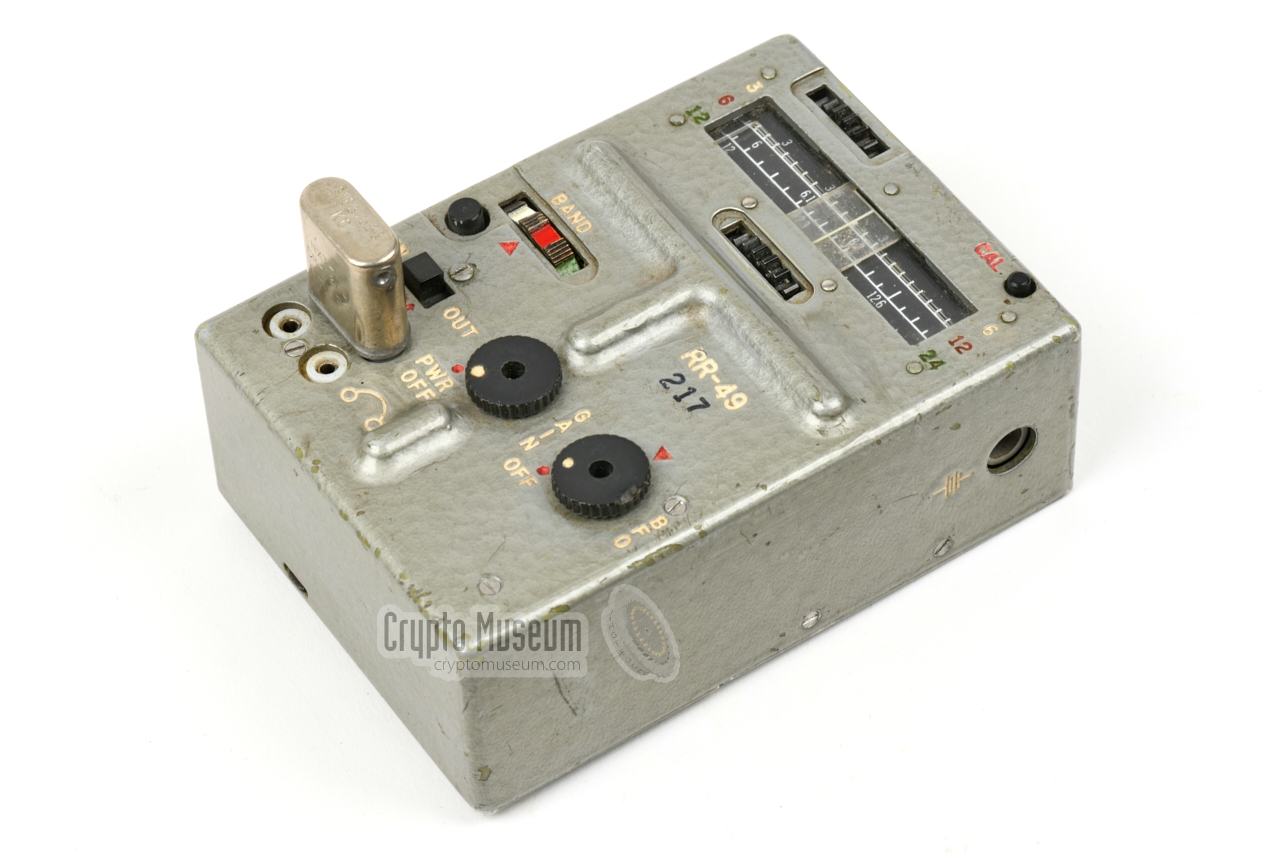
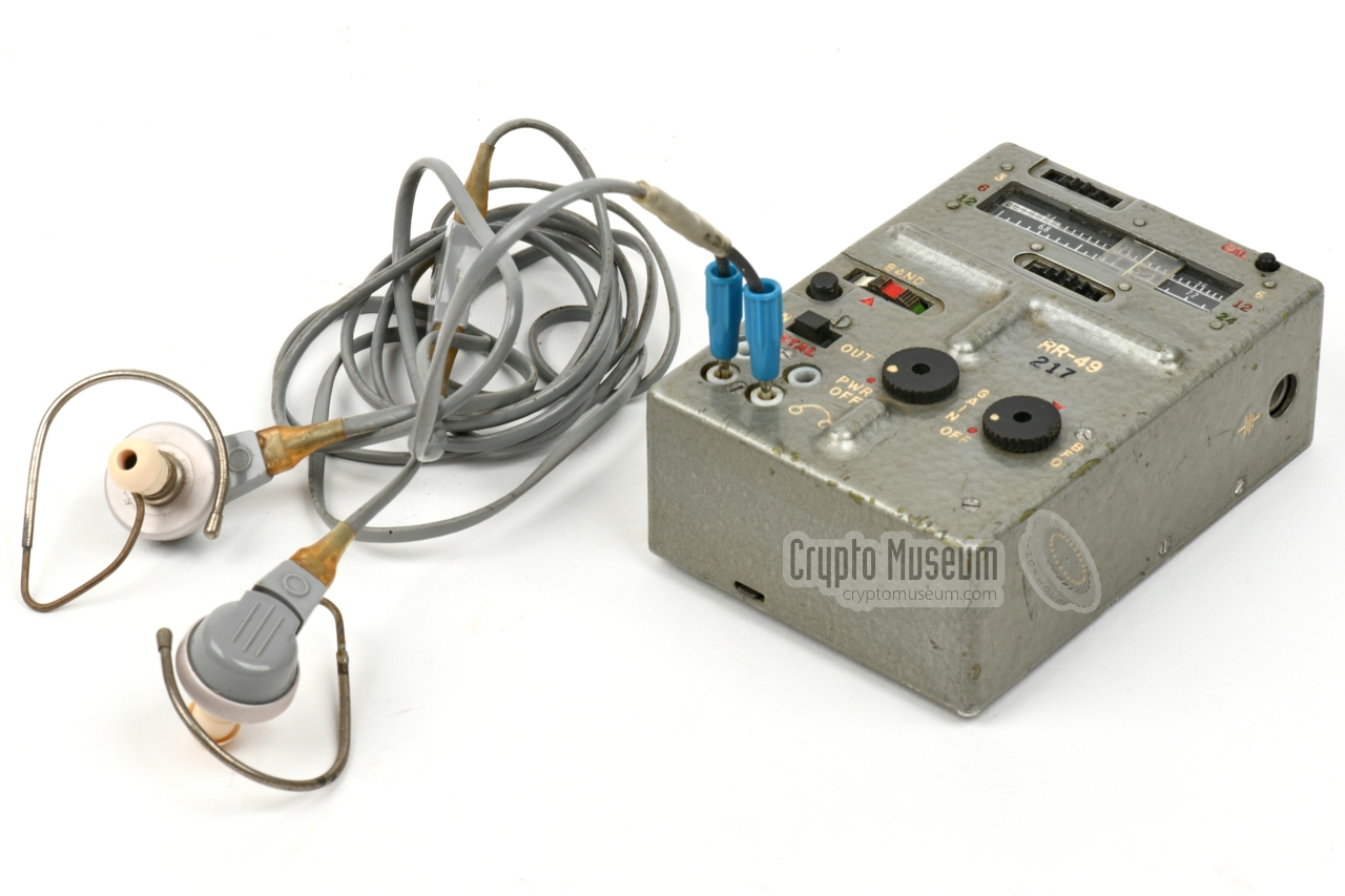
The device is housed in a molded metal case in grey hamerite colour,
that measures 100 x 71 x 40 mm and weighs just 370 grams without the 9V
block battery.
The device is suitable for AM and CW reception of Short Wave (SW)
frequencies between 3 and 24 MHz, divided over 3 bands.
The frequency can be freely adjusted with coarse and fine tuning knobs in
combination with the frequency scale at the upper edge. Alternatively,
the frequency can be determined with a crystal – shown in the image on
the right – which can be useful when using predetermined channels.
|
|
|
The RR-49 was initially developed for the RS-49 spy radio set,
but was released separately before the complete set was ready.
As a result, it
also became a popular stand-alone receiver for agents operating in a
(hostile) foreign country, not least because of its low power consumption.
It could be used for 18 to 20 hours from a single standard 9V block battery.
The device is known to have been used by
the American Central Intelligence Agency (CIA),
as well as the German BND [3].
The device is functionally similar to the German
BN-48 (UHU) receiver, that was released in 1958.
The receiver by itself was also used by the Belgian State Security Service
(Staatsveiligheid) [1]. It is likely that these receivers were intended for
the Belgian Stay-Behind Organisation SDRA-8.
It is also known that the RR-49 was often presented to
former CIA communications officers on their retirement, until at least 1995.
This suggests that there might have been a surplus stock [1].
|
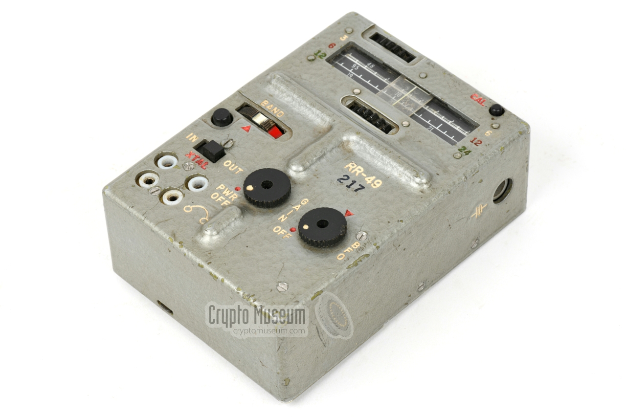
The image below provides an overview of the controls and connections of the
receiver. Apart from the external power socket and the antenna terminal,
all connections and controls are located at the top surface.
At the front left are two sockets: one for the
connection
of a pair of earphones,
and one for a crystal with a
HC-6/U base.
If the crystal is not used, the receiver can be used with the internal
Variable Frequency Oscillator (VFO) by setting the
XTAL selector to OFF.
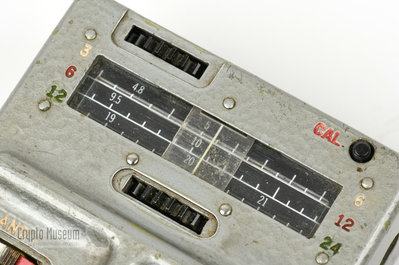
In VFO-mode, the frequency can be adjusted with two knobs – coarse and fine –
in combination with an accurate film scale. The scale can be calibrated by
pressing the CAL button, turning the frequency controls until a tone is heared,
and then shifting the white hairline at the centre of the frequency scale
until it lines up with the nearest 1 MHz mark on the frequency scale.
A wire antenna should be connected to the spring-loaded terminal at the
left side.
The terminal can be released with a knob at the top surface.
Surprisingly, there is no ground terminal.
When the device is used in combination with the
RT-49 transmitter,
the antenna would be routed through it.
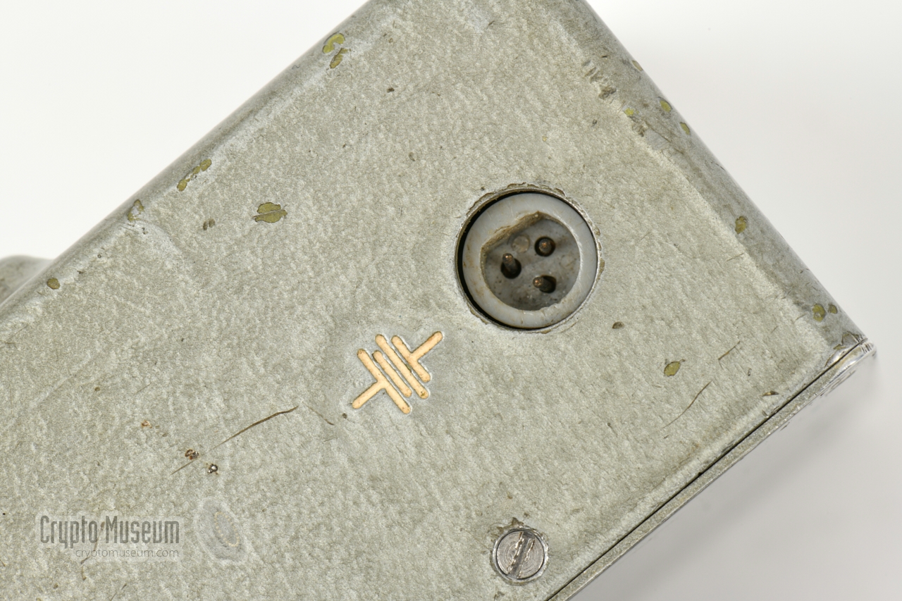
The device is
powered by an external 12V DC source – connected to the 3-pin socket at
the right – or by a 9V battery that can be installed in the
battery compartment at the bottom.
|
- RR-49
This is the initial version, introduced around 1964 and made by
Collins Radio
in Cedar Rapids (Iowa, USA).
The device featured here is of this type.
- RR-49-001
This is a slightly later version, also made by
Collins Radio and introduced
in December 1965. The circuit contains several improvements over the original
design of 1964.
- RR-49A
This is a later version, made by Delco Electronics.
It is externally identical to the above versions.
|
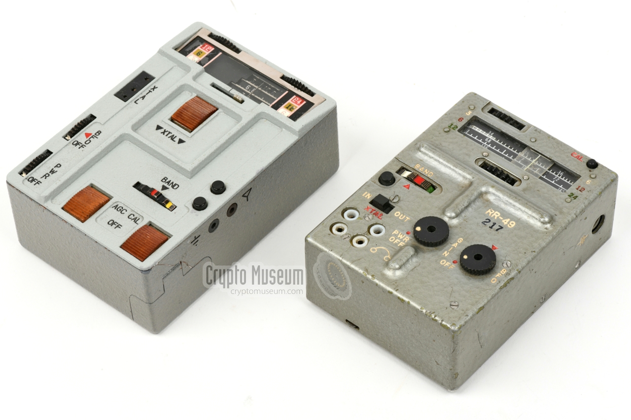
The RR-49 is very similar to the A-610 (SEZHA)
that was used by the intelligence services of the former USSR
– the KGB – for the same purpose. The two receivers
are shown side-by-side in the image below. Not only are the dimensions
similar, the functions and features are nearly identical. It seems therefore
likely that the Soviet A-610 (SEZHA) was modelled after the
American RR-49.
Apart from the similarities, there are also differences. The front panel of
te A-610 is made of die-cast aluminium, whilst the RR-49 is housed in a molded
enclosure. The crystal socket of the A-610 is suitable for
different types of crystals,
whilst the RR-49 is only suitable for
HC-6U crystals.
➤ More about the A-610 (SEZHA)
|
Below is the block diagram of the RR-49 receiver. At the left is an RF
pre-amplifier, followed by a mixer where the signal from either the VFO
or the crystal oscillator (XTAL) is added, resulting in an IF signal that
is further amplified and passsed through a 455 kHz ceramic ladder filter. The
resulting signal is then fed to an AM detector and amplified in an AF stage
to headphones level.
For the reception of CW signals (morse), an adjustable Beat Frequency Oscillator
(BFO) can be enabled by moving its knob from the leftmost position. The signal
from the BFO is injected directly into the IF Amplifier. It produces an
audible tone when the morse signal is active.
|
|
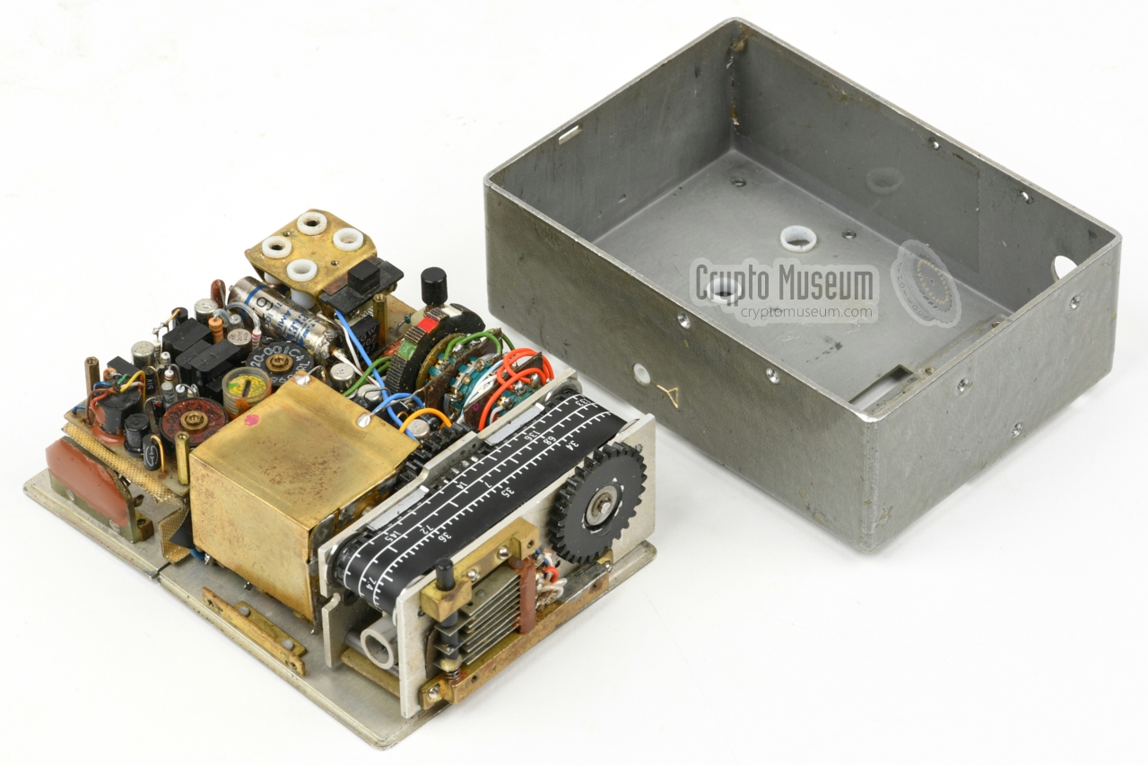
The enclosure consists of a metal base plate – with a hinged lid covering
the battery compartment – and a molded case shell. The latter is held in place
by 7 screws: 2 at the left, 2 at the right and 3 at the top. The
interior can be accessed by removing these screws in addition to the two
black knobs of the GAIN (volume) and BFO controls (release the small screw at
the centre of the knob).
|
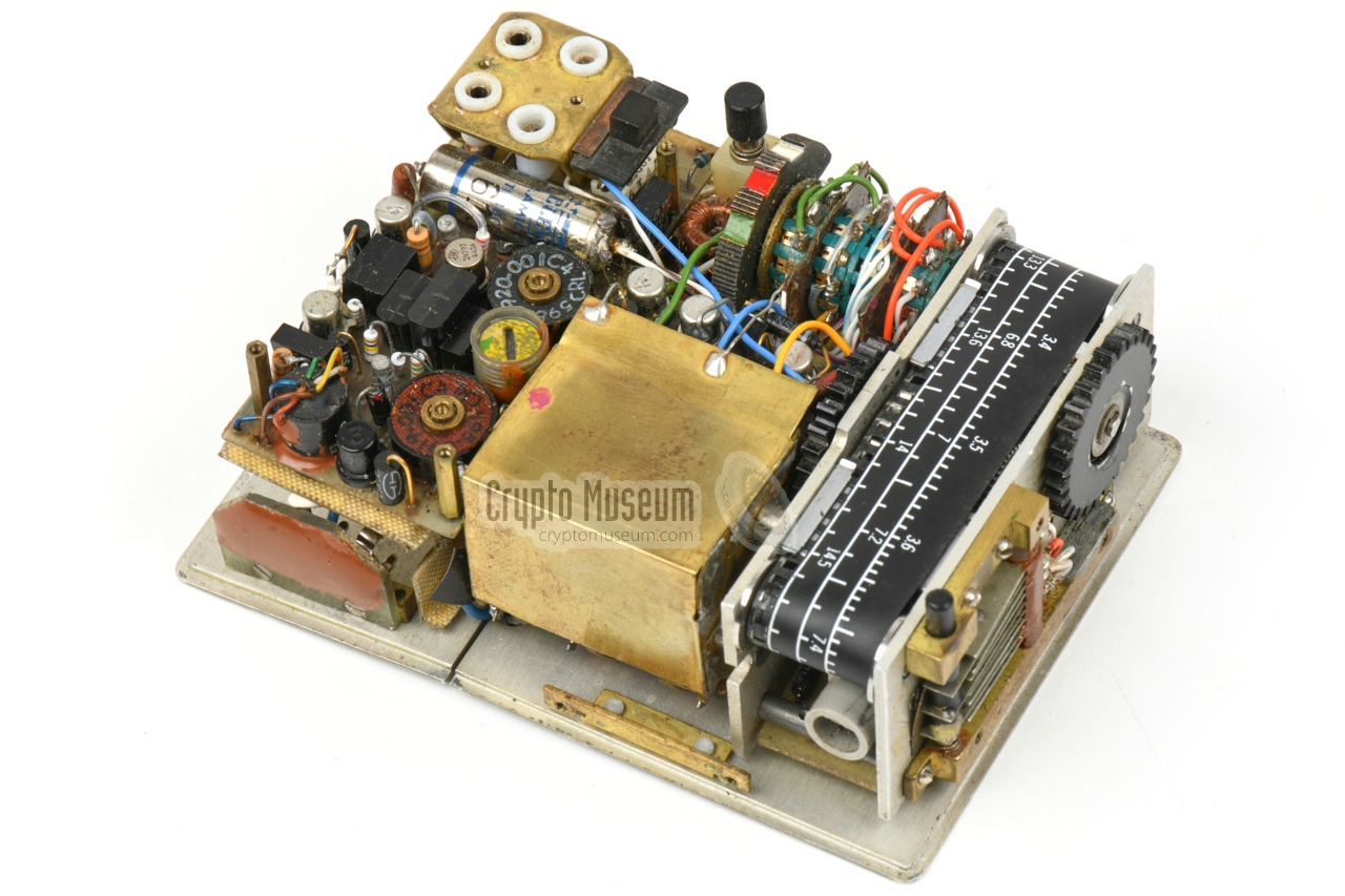
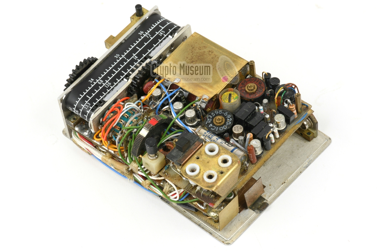
The case shell can now be removed, as shown in the image on the right.
All mechanical and electronic parts are mounted to the base panel.
Due to the highly compact construction, the device is not very service-friendly
and would have to be taken apart completely
in case it had to be repaired or adjusted.
Nevertheless it had an extremely long lifespan. The receiver featured here is
still fully operational after more than 50 years, which is generally not the
case with most modern domestic equipment. Apparently, only first class
components were used for the RR-49.
|
|
|
|
The image above shows the interior of thereceiver as seen from the top right.
At the front is a sub-frame with a tape- or film-type frequency scale.
Note that the calibrate-switch is mounted to the top of this frame.
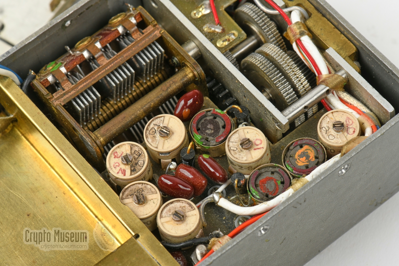
Also note that the 3-gang tuning capacitor is shielded with a brass panel.
|
Device Portable short wave receiver Purpose Agent communication Model RR-49 Country USA Manufacturer Collins, Delco Year 1964 User CIA, BND, SDRA-8 Purpose Agent communication Principle Superheterodyne Circuits RF amplifier, Mixer, LO, IF, Detector, BFO, AF Frequency 3 - 24 MHz Bands 3 (see below} Calibrator 1 MHz intervals (±0.5%) Modulation AM, CW, MCW Sensitivity 10dB S/N 1 Selectivity 3dB (5kHz), 6dB (12kHz), 40dB (16kHz) IF 455 kHz BFO ±4 kHz Rejection Image: -20dB (3-18 MHz), -10dB (>18 MHz)
IF: -55dB Response 300 - 2500 Hz (±3dB) Battery 9V block battery (18-20 hours) Power 12V DC (external) ±10% Consumption 75 mW Accessories Earphone Temperature -30 to +45°C Storage -40 to +60°C Dimensions 100 x 71 x 40 mm Weight 370 grams (without battery)
|
-
AM: 0.1mW, 15µV input, CW: 0.1mW, 5µV input.
|
White ● 3 - 6 MHz Red ● 6 - 12 MHz Green ● 12 - 24 MHz
|
- RR-49 Receiver, Operating Instructions
CIA, date unknown. Approved for release by CIA on 23 April 2014.
- RR-49 circuit diagram 1
CIA, date unknown, but probably 1964.
- RR-49-001 circuit diagram 1
CIA, first drawn 1964, last updated 2 December 1965.
- Instruction Book, Receiver RR-49 1
Collins Radio,
1964, 1965, 1966. 2nd Edition, February 1966.
|
-
Kindly provided by Pete McCollum [1].
|
- Trip Report - Development f the RT-49 and RP/A-49
CIA Memorandum, 28 February 1963
- Chief, OC-OS to Chairman, Equipment Board, Equipment Procurement
CIA Memorandum, 2 January 1964
- Equipment Board staff meeting, Agenda
CIA, 9 January 1964
- CIA Equipment Board staff meeting, minutes
9 January 1964
- Trip Report - RT-49/RP-49
24 November 1964
- Trip Report - RT-49/RP-49
22 December 1964
- Trip Report - RR-49
22 December 1964
- Inspection Report No. 1 - AN/B-62
CIA Memorandum, 11 May 1966
- Inspection Report No. 5 - RT-49/RP-49
17 June 1966
- Inspection Report No. 6 - RT-49
CIA Memorandum, 21 June 1966
- Inspection Report No. 2 - AN/B-62
CIA Memorandum, 24 June 1966
- Equipment Board Meeting, Agenda
CIA, 8 November 1967
- Long-Range HF Communications Equipment
7 April 1969
|
|
|
|
Any links shown in red are currently unavailable.
If you like the information on this website, why not make a donation?
© Crypto Museum. Created: Thursday 05 November 2020. Last changed: Wednesday, 05 November 2025 - 12:10 CET.
|
 |

|
|
|


![Secret CIA polaroid photograph of RS-49 agent radio [4]](img/rs49_1_thumb.jpg "image # rs49_1_large.jpg")
![Secret CIA polaroid photograph of RS-49 agent radio [4]](img/rs49_2_thumb.jpg "image # rs49_2_large.jpg")

![Secret CIA polaroid photograph of RS-49 agent radio [4]](img/rs49_1_large.jpg)
![Secret CIA polaroid photograph of RS-49 agent radio [4]](img/rs49_2_large.jpg)


