|
Cold War USSR KGB GRU R-394 R-394T → ← R-394K
Digital spy radio set with burst encoder · USSR
R-394KM, codenamed Strizh-KM (Russian: Стриж), 1
was a digital SW spy radio set,
developed in the early 1980s in the
Soviet Union (USSR), as the
successor to the analogue R-394K.
It was used by the Special Forces (SF) of the countries of the
Warsaw Pact.
The agent version of the radio is known as R-394T, and was used
by intelligence services like the KGB and GRU. 2
It was the last model before the fall of the
Iron Curtain in 1989
and the collapse of the Soviet Union in 1991.
|
The modular radio is housed in a watertight metal carrying case
– similar to that of the earlier R-394K –
and is powered by an external 12V DC source.
It is suitable for the 1.5 - 13.5 MHz frequency range and features
a digital phase-locked loop (PLL) with split RX/TX frequencies.
In addition, it has a built-in digital burst encoder with room for 203
datagrams, each consisting of 5 digits. When transmitting,
the datagrams are sent in morse code
at very high speed, in order to reduce the chance of interception and
location by means of Radio Direction Finding (RDF).
|
|
|
R-394KM was introduced around 1983, and was used by all countries of the
Warsaw Pact. The Russian Army started using it around 1984,
but the NVA — the army of East Germany
(DDR) —
was relatively late and introduced the set in 1988.
The R-394KM radio sets were used until long after the end of the
Cold War.
The radio featured here was manufactured in July 1988 [D].
The agent-version of this radio set – with english lettering, western
connectors and without the storage case – is known as R-394T (Strizh-T).
Nevertheless, the (military) R-394KM was sometimes used by intelligence
services like the KGB abd GRU, especially when stowed in
clandestine caches in Western Europe.
Such cached R-394KM units have been found as late as 2020 [4].
|
-
Стриж (Strizh) is the Russian word for swift (bird).
-
The intelligence services sometimes used the R-394KM when
the R-394T was in short supply.
-
Transmission and reception frequencies are entered separately and
can be different.
|
- R-394KM (Strizh-KM)
This is the military variant of the radio. It is housed in a watertight
metal carrying case with padding on the outside, so that it could be carried
on the back by a soldier or by a member of the Special Forces (SF).
Most of the R-394KM radios found on the surplus market today, are of this type.
It has also been found in Russian caches in Western Europe [4].
This version and its accessories are further described below.
- R-394T (Strizh-T)
This is the agent-version of the R-394KM that was used by the
KGB
and other security services in the USSR
and the countries of the Warsaw Pact.
Although its interior is the same, the exterior is somewhat different.
It has a modular design and has English text on its control panel.
Furthermore, it is not mounted inside a military transport case.
➤ More about Strizh-T (the agent-version)
|
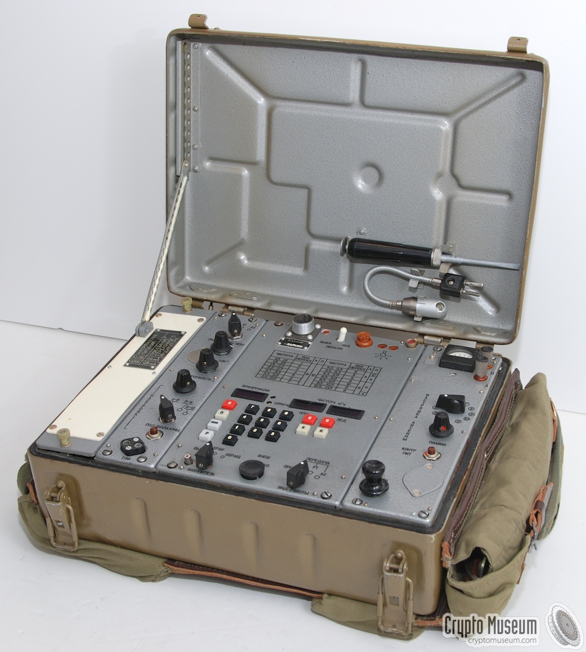
The radio is completely mounted inside the carrying case, and consists
of 4 major blocks. From left to right: the spare parts storage compartment,
the receiver (RX), the digital storage unit (DSU) and the transmitter (TX).
It is shown here with translated inscriptions:
The spares compartment contains some lamps, fuses, etc. (see below for a
full description). The receiver (RX) and transmitter (TX) are pretty straight
forward in operation, but the Digital Storage Unit (DSU) is slightly more
complex. TX and RX frequencies can be set individually from the DSU.
Any pre-coded messages are stored in the DSU's memory and can be transmitted
at will.
Three displays are present at the center of the DSU: one for displaying the
coded message (in groups of 5 digits), one for the RX frequency and one for
the TX frequency. The currently set frequencies can be checked by pressing
the corresponding CHECK key
(K).
The CLEAR button
(C) is used to clear the
display prior to entering a new setting.
Please note that RX and TX each have their own CLEAR and CHECK buttons.
For a detailed description, look here.
Just above the displays is a table with frequency ranges and the corresponding
settings for the RX preselector and the TX antenna matcher. Fine tuning is
done separately by following the procedure described in the user manual.
The table also specifies the required length of the wire antenna and the
counterpoise wire. A suitable antenna is supplied with the kit.
|
|
The radio operated on the HF band, covering all frequencies between
1.5 and 13.5 MHz. The transmitter (TX) is mounted to the right of the
Digital Storage Unit (DSU). It is synthesizer controlled and produces
an HF output of 10W (CW only). The TX frequency is set in the rightmost
display of the DSU.
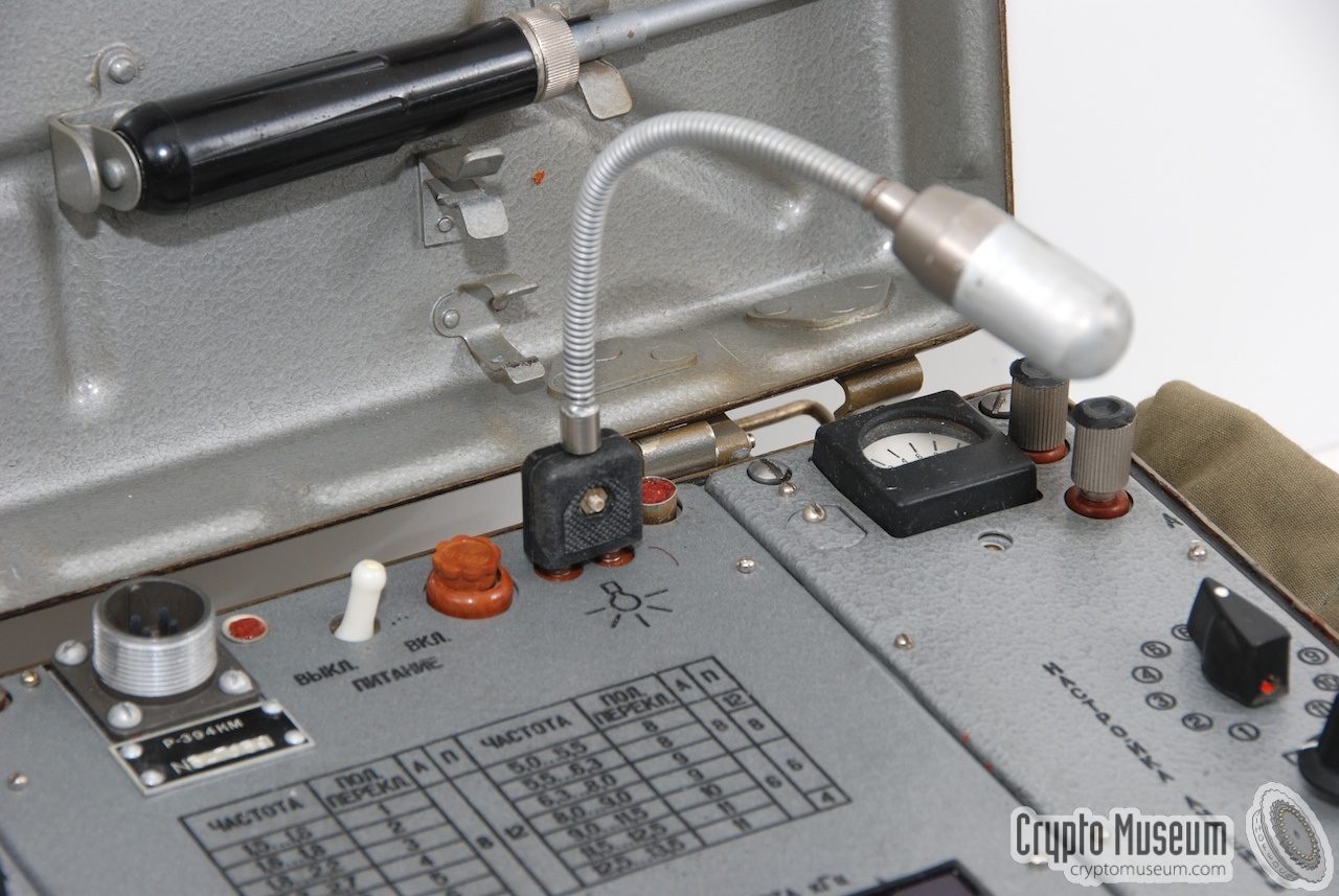
In order to obtain maximum TX output, the antenna matcher on the TX-unit
should be set appropriately for the selected frequency. A fine
control is used, in combination with a meter at the top right
(and an antenna current light), to adjust
for maximum antenna current.
|
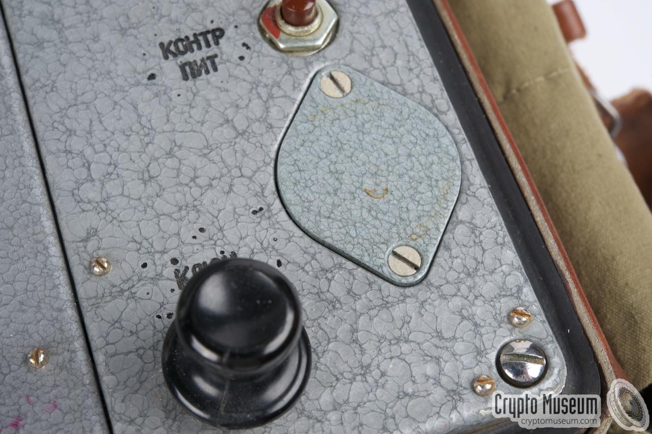
At the bottom right is a built-in morse key that can be used to send messages
manually. To the right of the morse key is a small oval lid that is held
in place by two bolts. It gives access to a 9V battery that is
used to retain the messages in the memory of the
Digital Storage Unit (DSU).
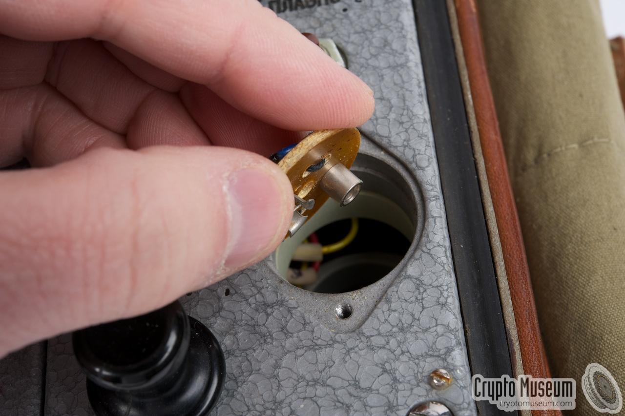
The image on the right shows the battery compartment after removing the
lid. The holder accepts a cylindrical Acacia battery (Russian: Акация),
which is actually a stack of 6 circular 1.5V cells. Without this battery
the memory of the DSU will be cleared when the radio is off.
|
|
|
With the battery in place, the contents of the DSU's memory will be retained,
as slong as the MEMORY selector is set to STORE, even when the set is switched
off. The memory can be cleared by turning the set off and placing the memory
selector in the OFF position. Wait a few seconds before turning it on again.
The OFF-position can only be engaged when pressing the small metal button
(to the left of the MEMORY selector) simultaneously.
|
|
The receiver (RX) is mounted to the left of the DSU. It is also synthesizer
operated and covers the same range as the transmitter.
It is a double-superheterodyne receiver with intermediate frequencies
of 40.5 MHz and 500 kHz.
The RX frequency is set in the middle display on the DSU and can be adjusted
in steps of 1 kHz.
A 4-position pre-selector is used to select the appropriate frequency range.
|
The middle section of the radio set is also the largest. It contains the
so-called Digital Storage Unit (DSU) that consists of a synthesized
transceiver and a digital burst encoder. Control of these two functions is
more or less integrated, in that they share the same numerical keypad.
|
The antenna should be connected to the transmitter. Usually a long-wire
antenna is used with sufficient counterpoise. The counterpoise is connected
to the topmost connector. Like most Russian spy radio sets of this era,
the receiver only performs satisfactory when a decent counterpoise is used.
The manual describes how to setup the supplied antenna for use with this
radio. One end could be tied to, say, a tree, whilst the other end is held
high with a light-weight telescopic fibre mast.
|
Power is supplied by a battery belt
that was usually supplied with the set.
It is also possible to connect any other 12V source to the radio, via the
4-way connector on its front panel. A short cable
is supplied to connect the R-394KM to an ordinary car battery.
According to [1] the R-394KM was powered
by an internal battery. Although this was quite likely, as the earlier
R-394K also had an internal 12V battery, no evidence for this
has been found to date.
Theoretically, a battery might be fitted in the leftmost
compartment (normally used for spares), but in none of the R-394KMs we have
seen so far, was there a power connection present in that compartment.
Nevertheless it might have been present on earlier models, or it might
have been used with an external cable.
There are also reports of an R-394KM that was found completely intact
in a field in Germany in the late 2000s. According to eye witness accounts,
the radio had a built-in battery that was still fully charged when it was
found [2].
This story might be related to the Strizh,
the spy-version of the R-394KM.
|
|
Below are some audio samples of the R-394KM, recorded by collector
Karsten Hansky in Germany in January 2019 [3].
The radio was connected to a dummy load and an
ELAD FDM-S1 was used to receive and record the signal. Further sound
processing was done with Audacity (software).
|
The radio can be powered by a set of batteries that are mounted together
in a canvas belt with suitable webbing so that it can be carried on the
body. They are charged by a 13.5V DC power source, such as
the mains battery charger below.
The belt consists of 10 'wet' cells, each of which delivers 1.2V
for a total of 12V DC. The cells are organised in two banks of five cells
each (one bank at either side of the body).
|
|
|
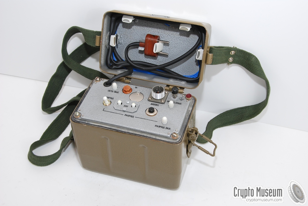
The battery belt shown above, was usually recharged with the mains
battery charger shown in the image on the right. It can be powered
by the 110V or 220V AC mains. A suitable mains plug is stored inside
the top lid of the device.
The charger can be connected to the battery belt by using the supplied
4-pin Power cable that was supplied with the set.
|
|
|
 |
|
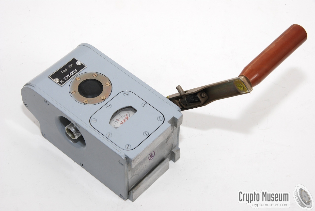
Hand-operated generator
PZU-5M
|
|
|
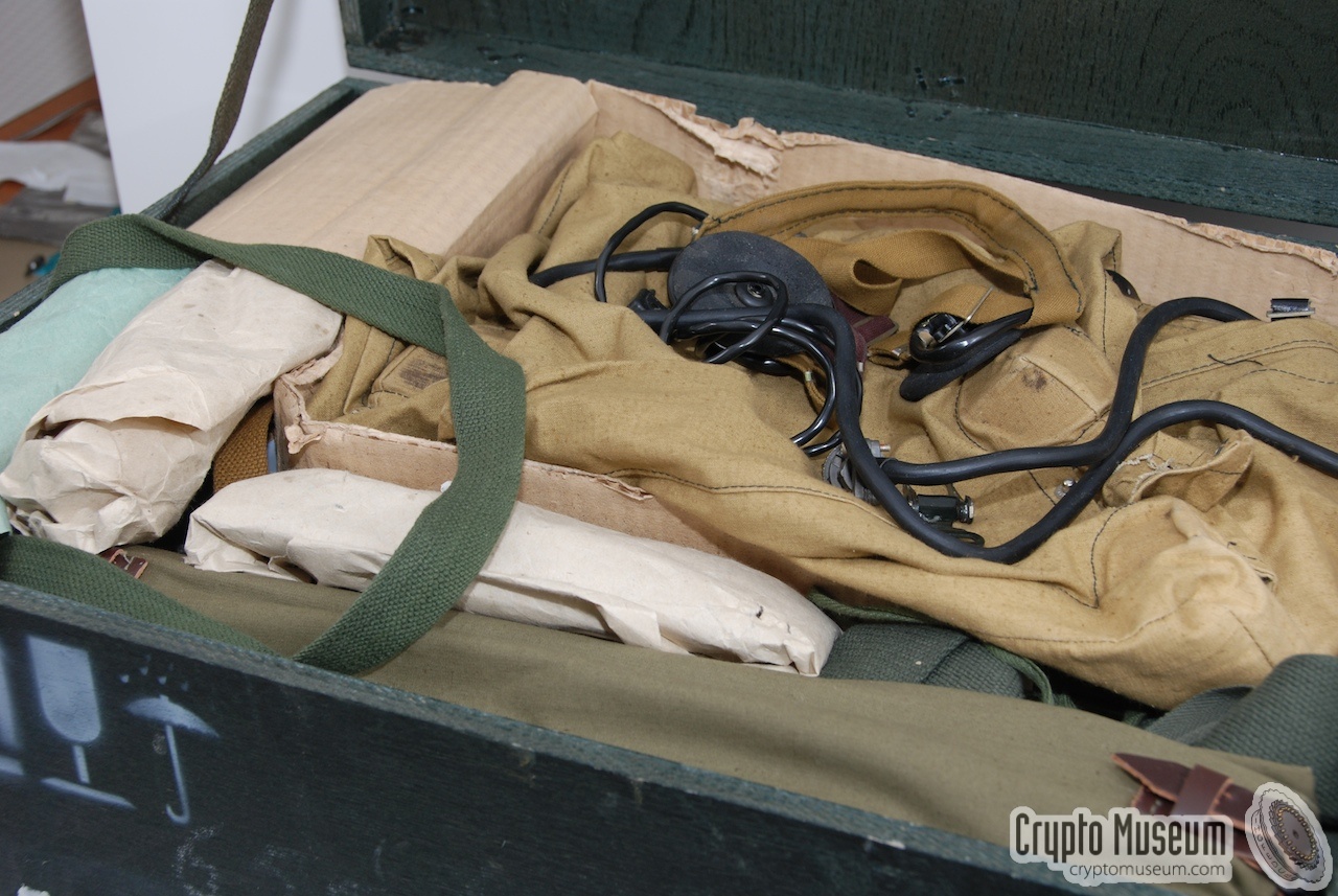
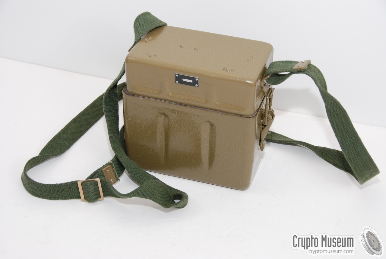
If no mains power is available, the battery can also be charged with the small
crank-operated power generator shown inthe image on the right.
Charging the batteries takes several hours, for just a few minutes of operation.
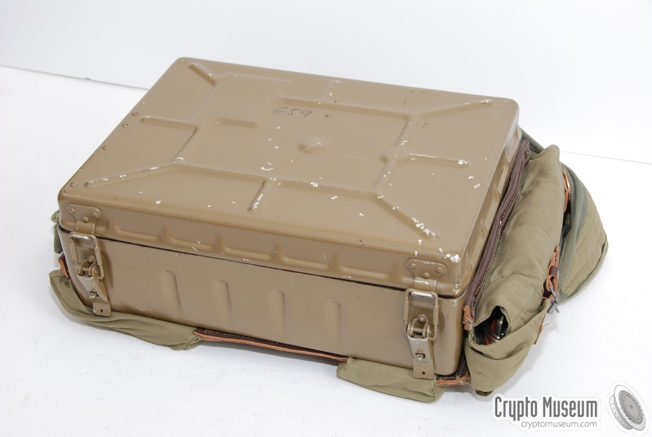
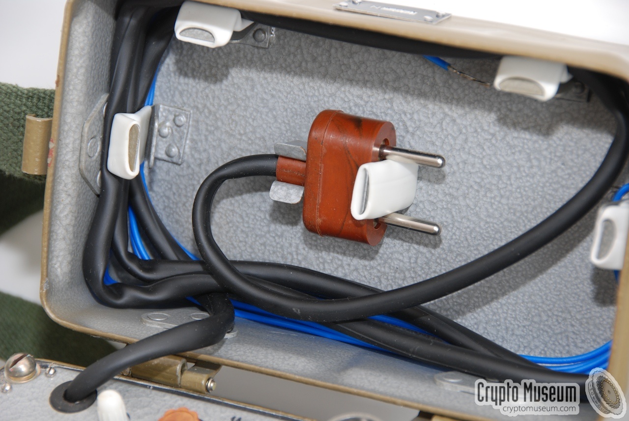
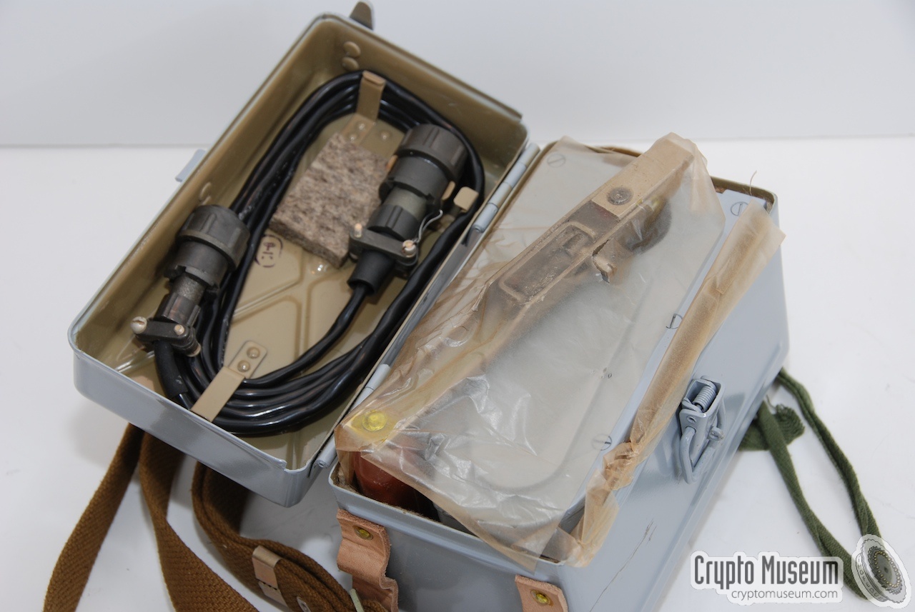
The generator is usually stored inside a
carrying case with a canvas strap.
The connection cables are stored inside the top lid of the case.
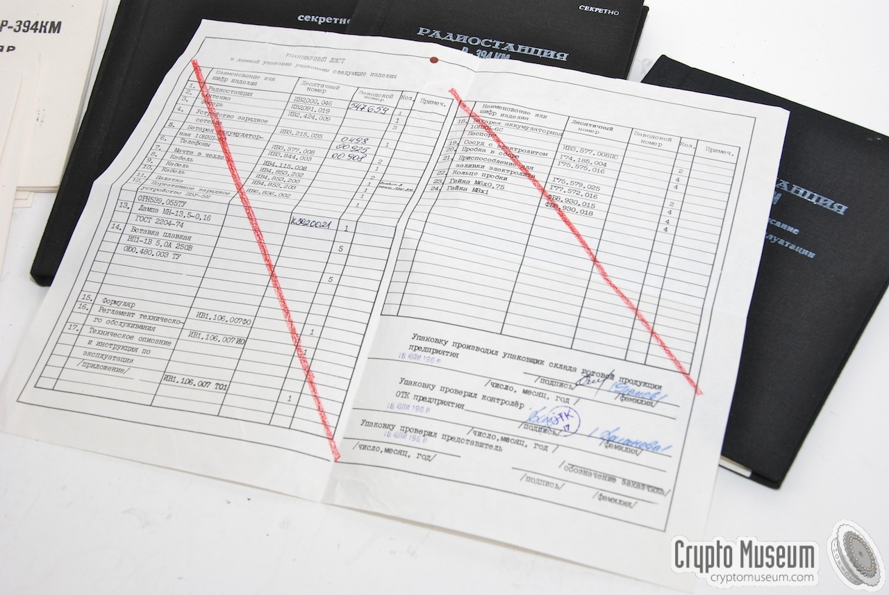
New generators were generally supplied in greased paper and stored inside in a
green wooden box,
together with a checklist and instructions.
|
|
|
The short 4-pin power cable shown in the image on the right, was
supplied for connecting the radio to a
suitable power source such as the 12V battery belt
or an external power supply unit.
The cable is about 1 meter long and has a standard 4-female plug at
one end and a matching male connector at the other end.
|
|
|
The cable shown in the image on the right, ca be used
to connect the R-394KM directly to an external power
source, such as a car battery.
One end of the cable contains the standard
4-pin female power plug that goes straight into the power socket of the
radio. The other end of the cable contains two clamps. The red wire is the
positive (+) terminal and the blue wire is the negative (-) one.
|
|
|
Almost any type of headset can be used with the radio.
In most cases, a common USSR military headset was supplied,
such as the one shown here.
It should be connected to the two-pin socket on the
left side of the radio's front panel.
Headsets of this type were commonly used with military
radio sets in tanks etc.
It has rubber ear pads and elastic head bands, so that it
can be worn under a helmet.
|
|
|
|
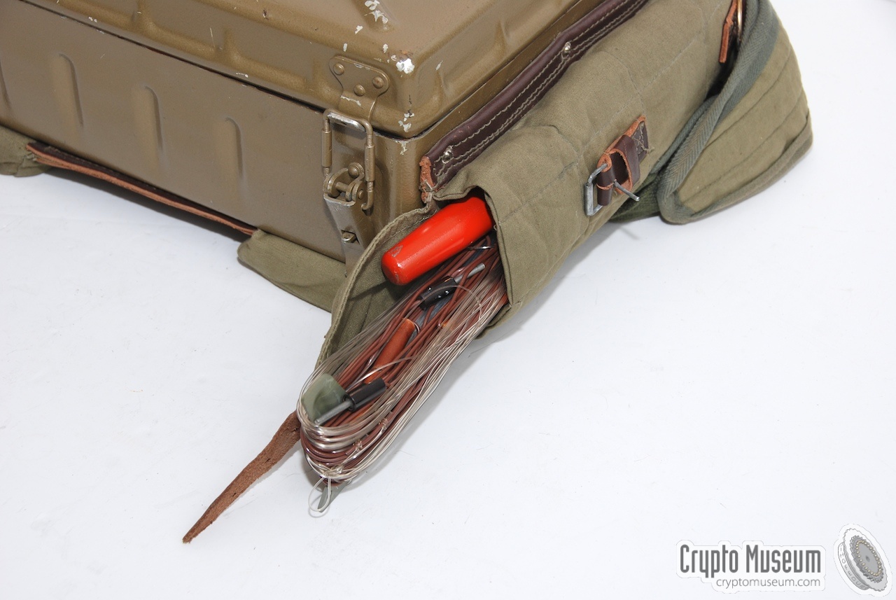
The antenna is usually stored inside a cavas packet to the right of the radio.
Depending on the way the radio is used, a second antenna might be needed as a
counterpoise. The second antenna (see the images below) can be stored in the same
pocket.
|
|
|
In order to setup the antenna as required, a light-weight telescopic glass
fibre mast is supplied. It allows the antenna wire to be mounted free from
obstacles and the earth. A ground pin is supplied to prevent the mast from
sliding away.
The mast and the ground pin are stored inside a canvas bag that can be strapped
to the radio or the canvas raincoat (see below).
|
|
|
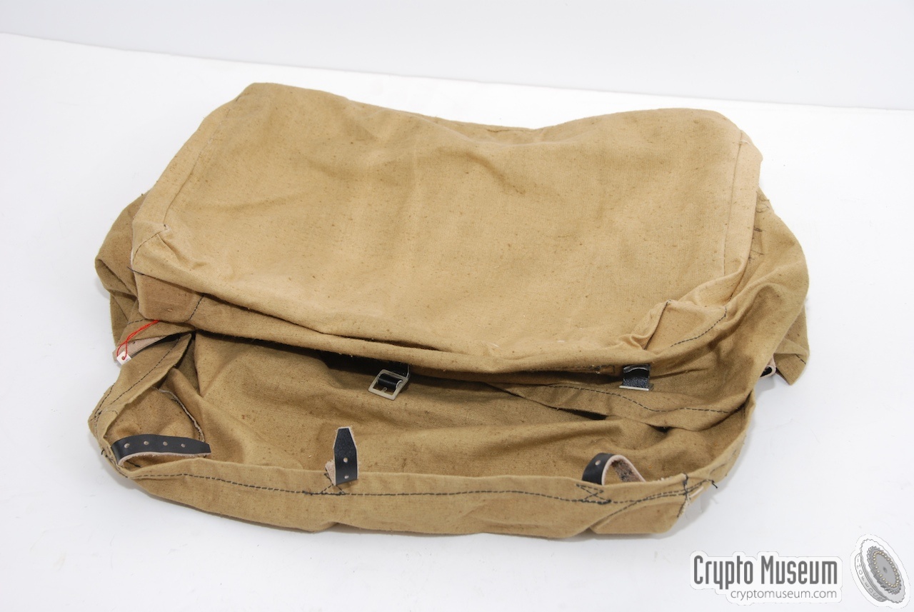
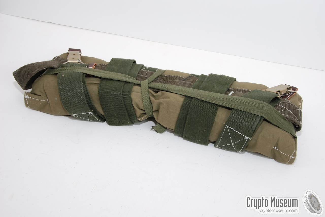
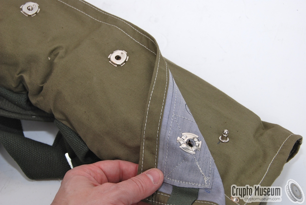
The radio is already painted in the usual Russian 'sand colour'
camouflage tint and has suitable padding at the bottom to allow the radio
to be carried on the back of the radio operator.
The lid of the unit is firmly closed with clamps and a gasket, to protect
the radio against dirt and water. Further camouflage is possible by fitting the
canvas raincoat shown on the right.
|
|
|
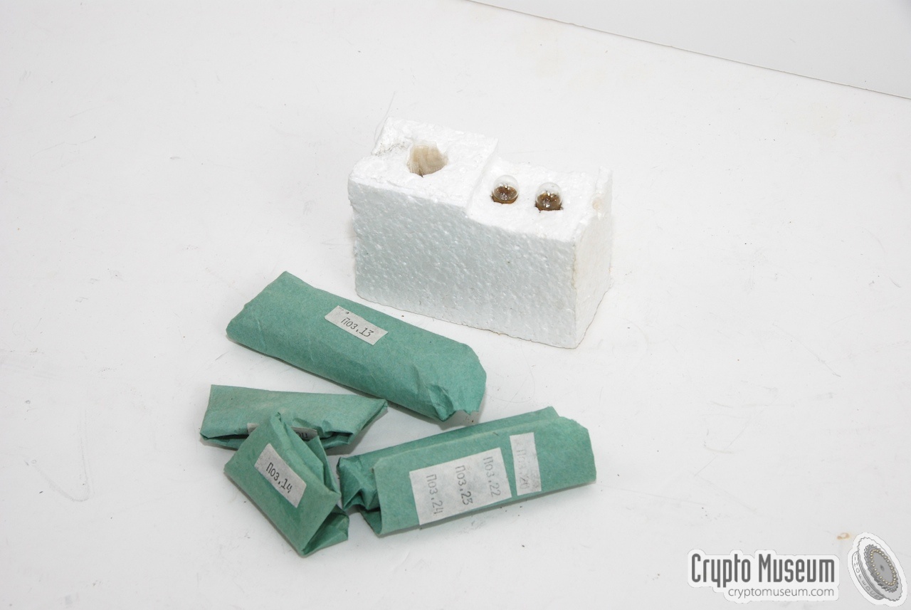
A set of spare parts is supplied with each R-394KM radio station.
Usually, these spares are stored in the special spares compartment
of the radio itself, hidden behind the leftmost panel.
The spares compartments contains a variety of fuses, lamps, bolts, etc.
as detailed in the checklist.
|
|
|
|
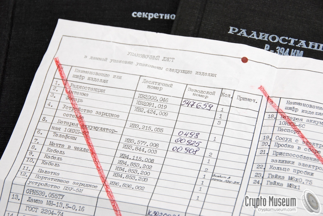
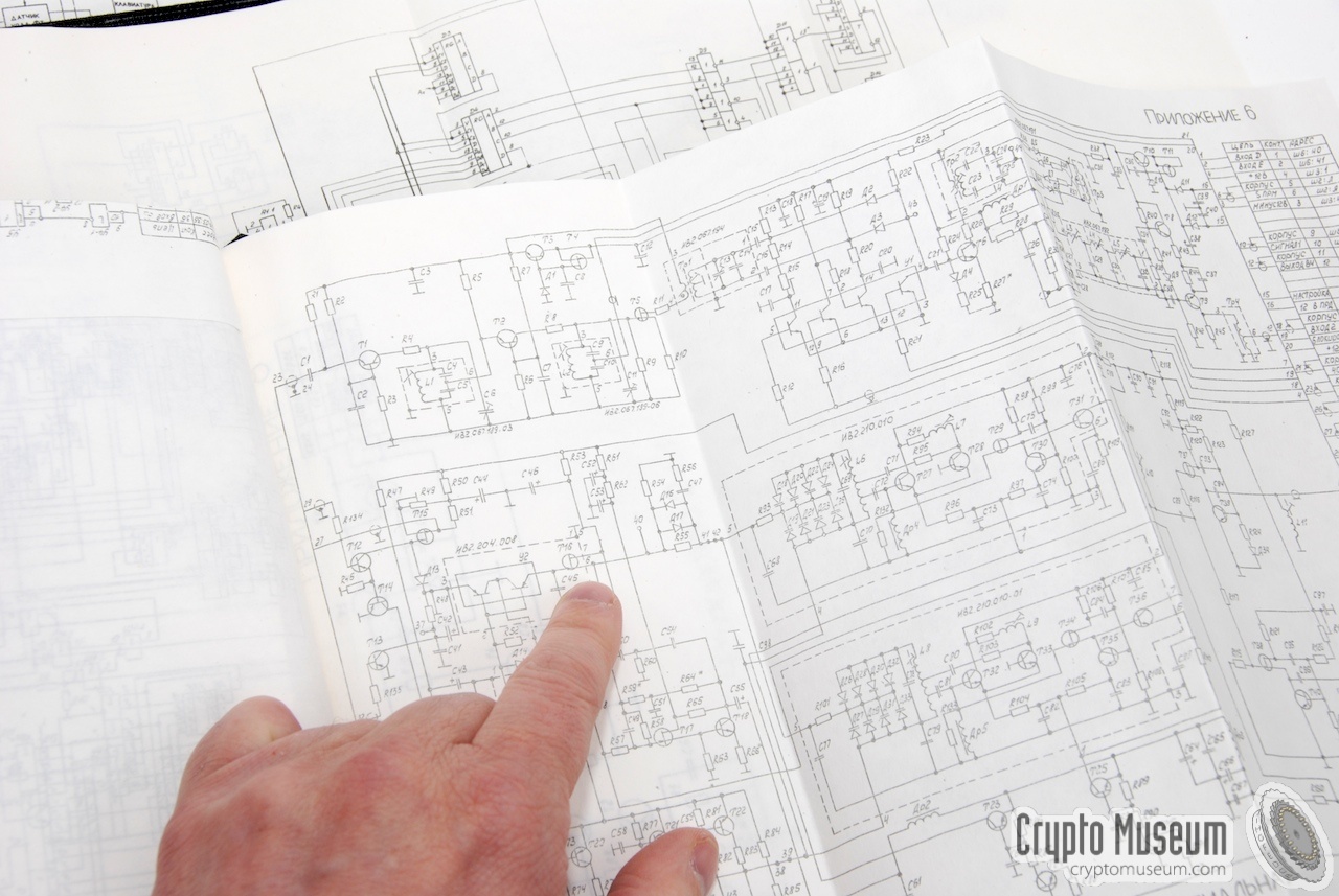
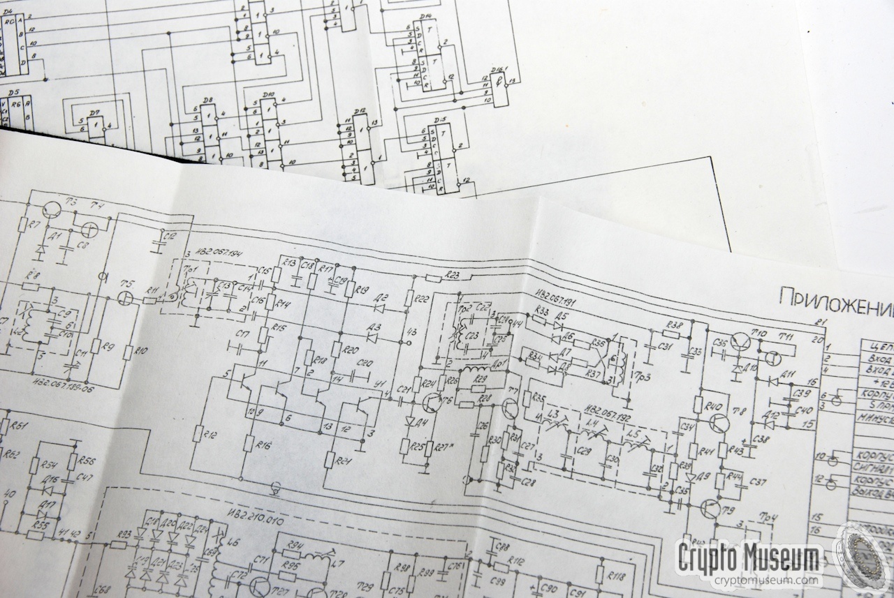
A complete R-394KM radio station comes with an an extensive set of
documents that are usually stored inside the large wooden storage box.
The documents include the operator's manual and full circuit diagrams
of the analog and digital parts. Some of the books are marked 'Secret'.
|
The following documents were supplied:
- Checklist
- R-394KM Operating Manual
- R-394KM Technical Description (analog)
- R-394KM Technical Description (digital)
- R-394KM Maintenance Book
- Battery Technical Instructions (2x)
- Battery Maintenance Book (2x)
Below are some close-ups of the various books and the checklist.
Two of the black books are marked 'Secret' in the top right corner.
|
|
|
A 10-pin expansion connector is present at the center of the DSU,
between the MEMORY and MODE selectors. This socket is sometimes protected
by a black plastic cap and is intended for the connection of
additional equipment such as an external morse keyer. It allows the transceiver
to be partly remote-controlled by the external device.
The connector has the following pin-out:
An external key can be connected between KEY and GND. Please note that the
radio has two KEY inputs: one used for AM (amplitude modulation)
and one for PM (phase modulation).
Also note that the pin-out of this socket is different from the same socket
on the earlier R-394K radio.
|
WARNING — Connecting an accessory that was
designed for one radio may cause permanent damage when being connected
to the wrong radio.
So, be careful when connecting an external device and check it first.
-
This contact is NOT wired on most R-394KM/Strizh units. When wired, it
provides a clock signal for an external keyer. In A2 mode, the clock signal
is 100 Hz. In F1 mode it is 250 Hz.
|
Device Spy radio set Purpose High-speed agent communication Origin Soviet Union (USSR) Year ~1983 Frequency 2 - 15 MHz (actually: 1.5 - 14.999 MHz) Steps 1 kHz VFO Digital PLL Modulation AM, PM, CW, A2 Output power 15 Watt Distance 150 - 1200 km Datagrams 203 groups (of 5 letters each) Manual 6-8 groups/min 1 Burst 167 groups/min Power 12 - 13.8 V DC (external) Battery Belt Current 0.7 A (RX) or 4.5 A (TX) Temperature -20°C to +40°C Humidity ≤ 98% (35°C) Dimensions 340 x 235 x 133 mm Weight 12.5 kg
|
-
Each group consists of 5 digits and a pause.
|
|
It is currently unknown how many R-394KM and R-394T
transceivers were built.
Judging from the serial numbers on recovered radio sets, it seems likely
that at least two batches were made: in 1983 and in 1988.
So far, we've recorded the following R-394KM serial numbers:
|
1983 360133, 380995, 380996 1988 547651, 547659, 547669, 547992, 548451
|
- Louis Meulstee, R-394KM
Wireless for the Warrier – Volume 4.
ISBN 0952063-36-0. September 2004.
- Anonymous source, Eye witness account of R-394KM found in Germany
Interview with Crypto Museum, 2009.
- Karsten Hansky, Sound samples of R-394KM transmitted signals
Germany, January 2019.
- 'Factory-fresh' Soviet spy radio discovered in German forest
Military History, 23 April 2020.
- Louis Meulstee, R-394KM
Wireless for the Warrier. Volume 4. Supplement Chapter 158.
January 2019.
|
|