|
|
|
|
|

|
|
USSR Cold War KGB GRU R-394 R-394KM → ← R-353
Analogue spy radio set with burst encoder · USSR
R-394K and R-394D, codenamed Strizh-K and Strizh-D (Russian: Стриж), 1
are self-contained short wave (SW)
radio sets for clandestine operations,
also known as spy radio sets, developed around 1975
in the former Soviet Union (USSR)
as the successor to earlier radio sets
like the R-353 and R-354.
They were intended for use by Special Forces (SF)
and for agent communication, by services like the KGB and GRU.
It features an analogue PLL and a built-in analogue or digital
burst encoder.
In 1983, the R-394(K/D) was succeeded by the all-digital
R-394KM and R-394T.
|
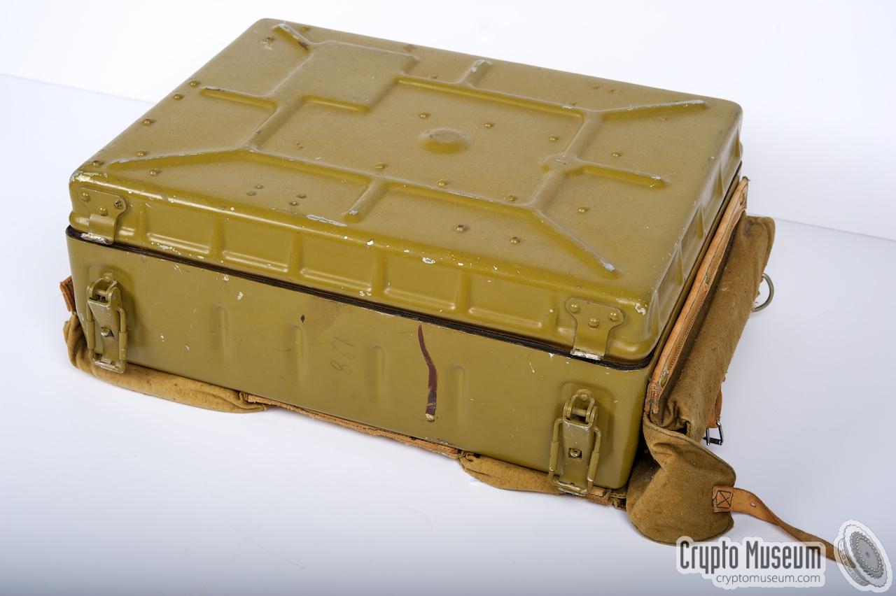
The modular radio is housed in a watertight metal carrying case
– similar to that of the later R-394KM –
and is powered by an internal 12V battery.
The transmitter uses an analogue phase-locked loop (PLL)
and can be adjusted between 1.5 and 13.5 MHz in 1 kHz steps.
The crystal-controlled receiver has 190 fixed channels and an
always-on beat frequency oscillator (BFO) for the reception of CW signals.
At the far left is the high-speed burst encoder.
Accessories like headphones, screwdriver, spare fuses and light bulbs are stowed
in the top lid.
|
|
|
-
Стриж (Strizh) is the Russian word for swift (bird).
|
- R-394K
This is the most common version of the R-394K. It consists of
a transmitter and receiver with an analogue PLL, and a mechanical
tape-based burst encoder that is fitted at the left.
- R-394D
This is an extremely rare version of the R-394K that has a digital
burst encoder fitted at the left, instead of the mechanical tape-based
one. It is believed that this variant was short-lived and that it was
replaced soon after its introduction, by the R-394KM.
|
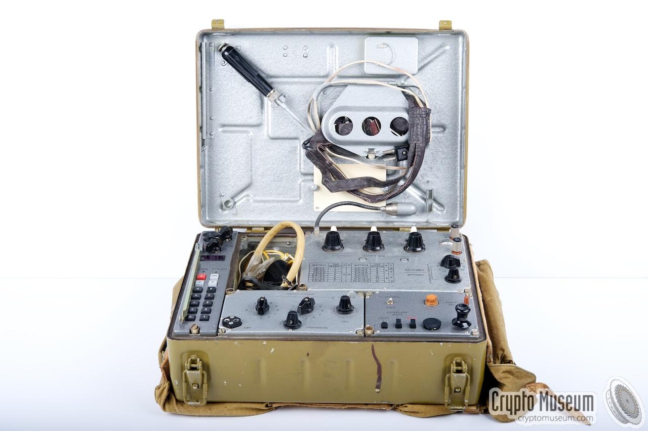
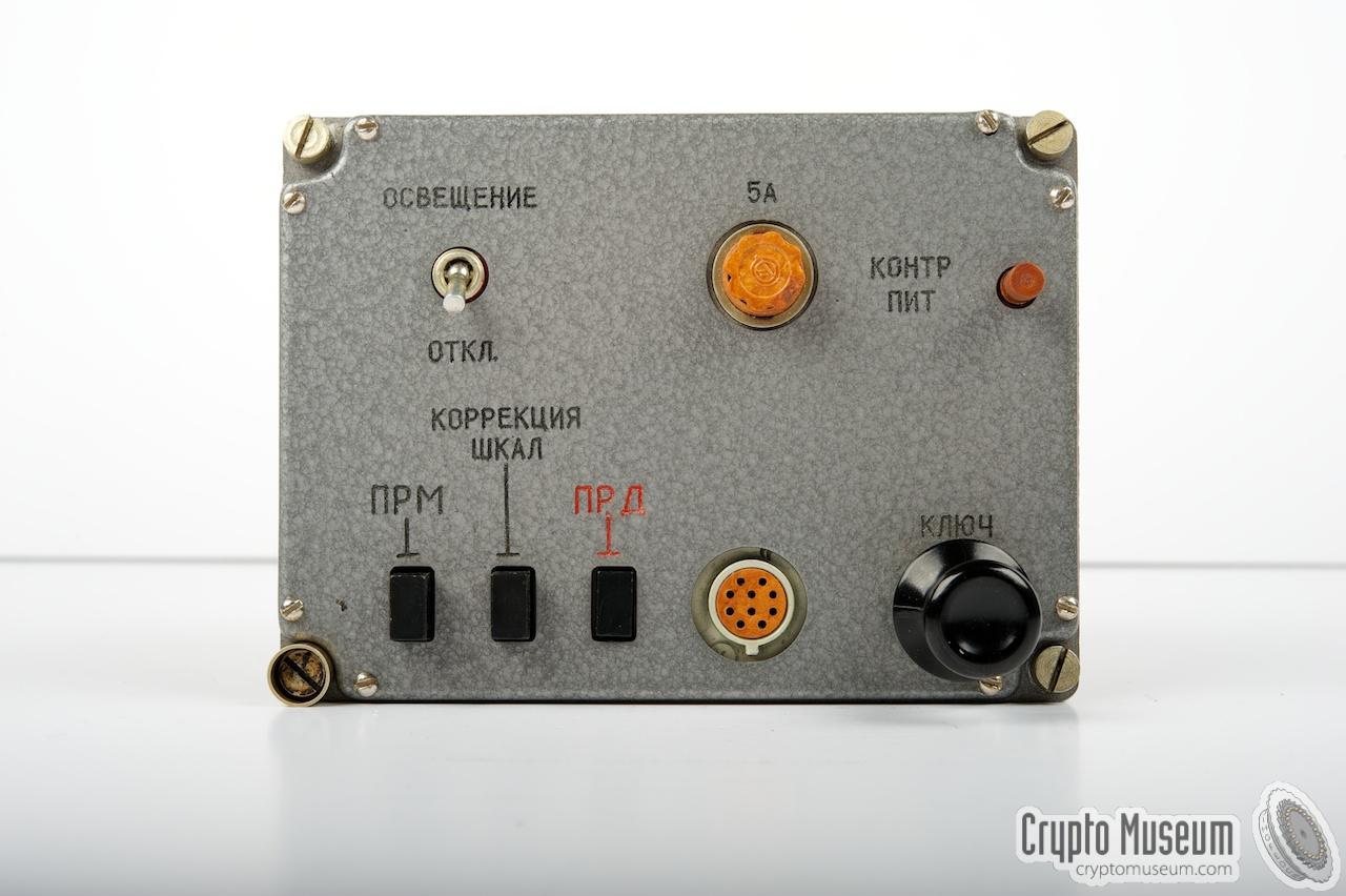
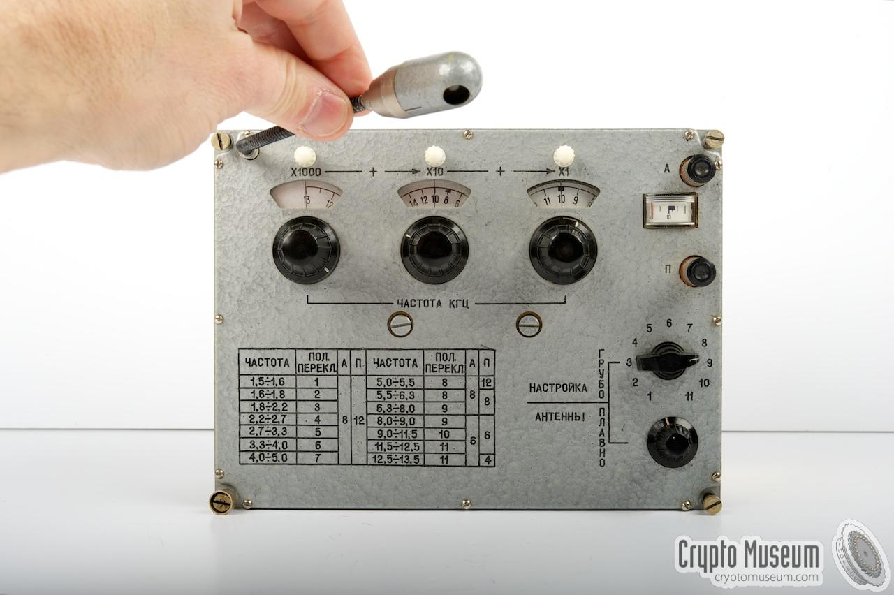
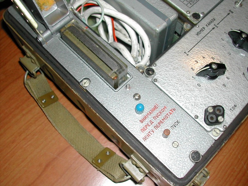
Below is an overview of the control panel of the earlier R-394K
with the analogue tape-based burst encoder at the far left.
The Russian text has been replaced by suitable English translations.
At the center of the leftmost unit is a large 'blob' which is
actually a cover that protects the plastic tape cassette.
At the bottom left is the start button of the tape player,
with a warning: rewind the tape before starting.
The external power connector at the top left is not present
on all models.
|
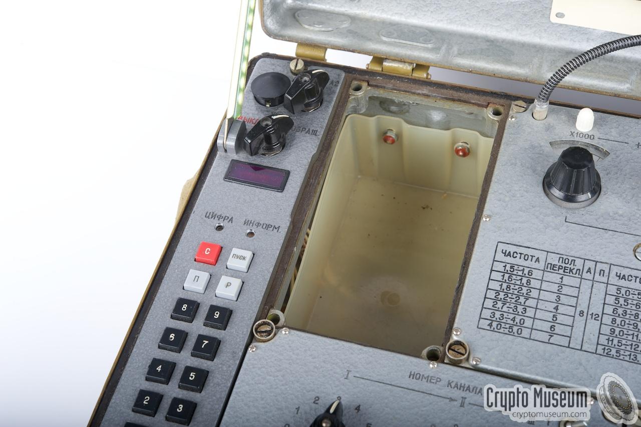
The drawing below shows the control panel of the later R-394D.
In the image, the Russian text has been replaced by suitable English
translations.
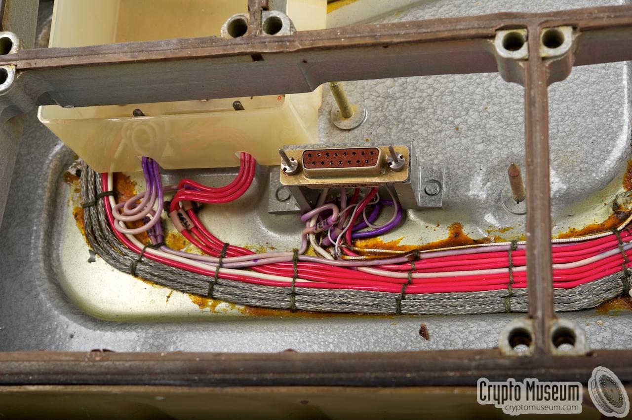
At the left is the digital burst encoder that is described further
down this page. It is connected to the rest of the radio set via an internal
15-way sub-D connector (DB15). Immediately to the right of the burst encoder
is space for a 12V battery. At present, we do not known if there was a connector
for an external power source.
Apart from the burst encoder, the two versions of the R-394K are idential.
The antenna and a suitable counterpoise are connected to the terminals at
the top right of the transmitter. The bottom two units are the receiver
and the power supply unit. An external 10-button morse keypad, can be
connected to the PSU. All modules (blocks) are fully described below.
The digital burst encoder of the R-394K Mark II is identical in
operation to the encoder of the later R-394KM.
|
|
Two different versions of this radio are known: one with an analogue
(tape-based) burst encoder, and one with a digital burst encoder.
Apart from the burst encoder, the two radios are identical.
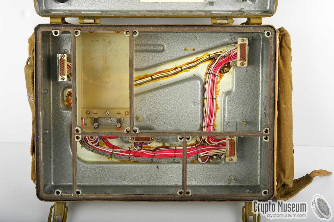
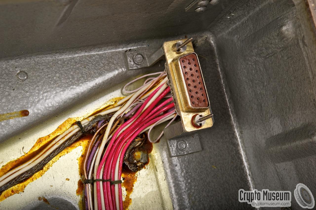
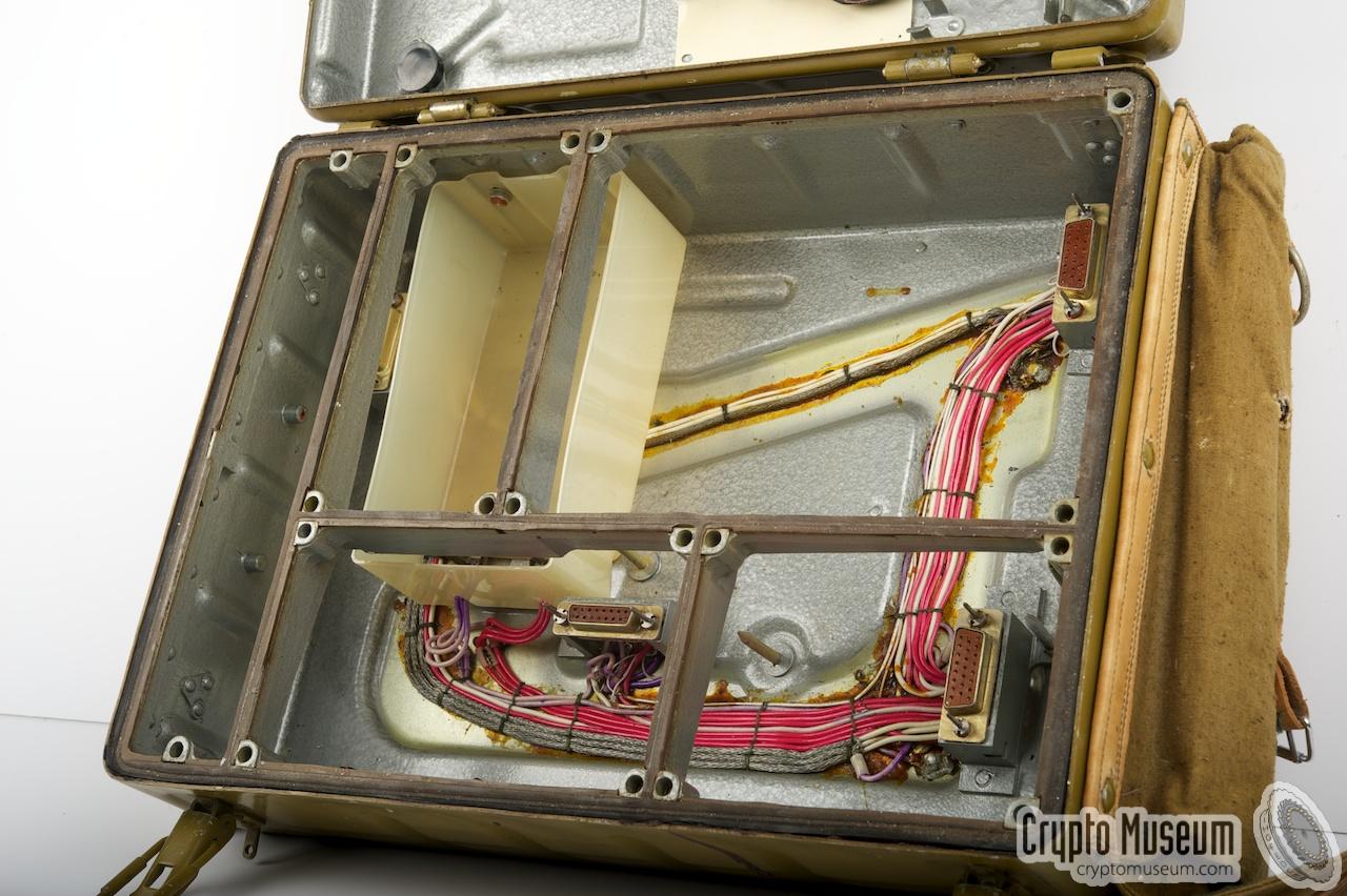
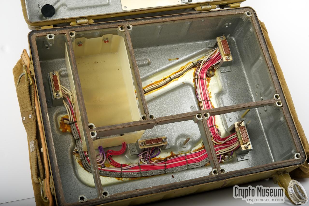
The radio has a fully modular service-friendly design.
The main wiring between the units is fixed inside the chassis and each
unit plugs straight into the chassis by means of sub-D connectors.
|
Apart from the battery, there are 4 functional units,
or Blocks, as the Russians call them:
- Transmitter (TX)
- Burst Encoder
- Receiver (RX)
- Power Supply Unit (PSU)
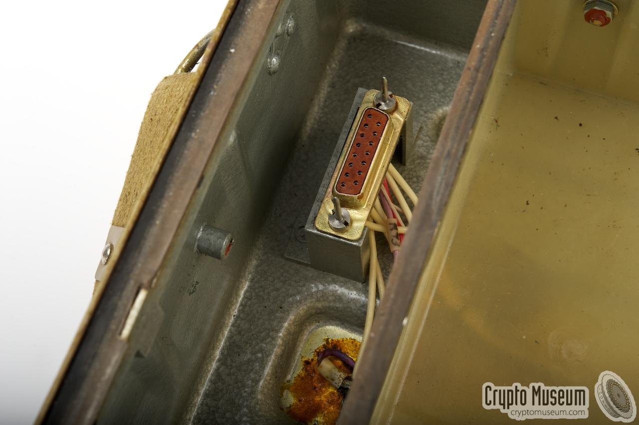
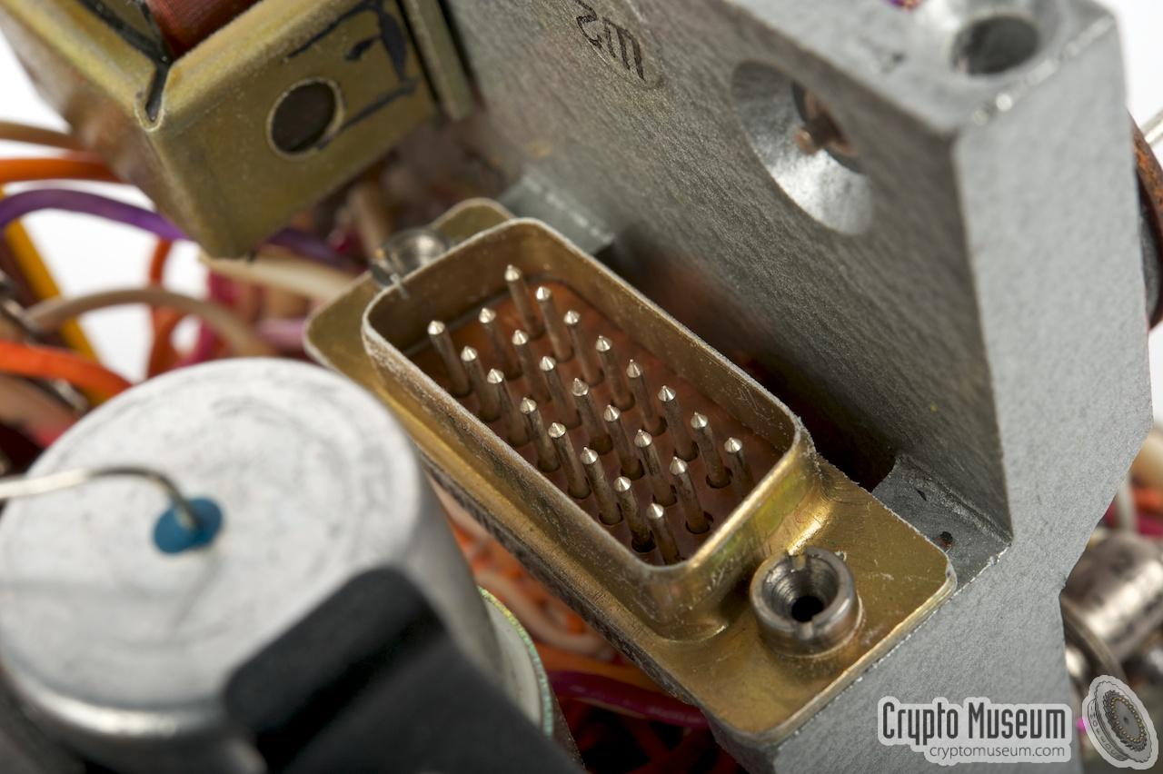
Four female-type sub-D sockets are mounted on a stub inside
the chassis, in such a way that they mate with the male-type
connectors on each of the units. Additional guide pins at the bottom
are provided to firmly lock the units in place.
|
|
|
|
Each unit is fully self-contained.
In case of a defect, a module can easily be removed and replaced by a
new one, without losing the alignment of the other units. This way it
was possible to replace the analogue tape-based burst encoder
with a digital one when new techniques became available.
The digital burst encoder is a functional replacement for the old one
that had become obsolete.
|
|
The unit at the bottom right (block 2) is the power supply unit (PSU).
The battery voltage (12V) is distributed throughout the radio by this unit.
Furthermore, a stabilized voltage of 8V is produced for the external
morse generator and several other parts.
Three black rectangular shadow-type push-buttons at the bottom left
are used to selected the main mode of operation [A].
|
The leftmost button selects the receiver, whilst the rightmost
button (marked with red text) enables the transceiver. The middle
button is used to enable the calibrator (marker).
The radio is turned off by pressing one of the 3 buttons
half-way down, so that they are all released.
The switch at the top left is used to turn the overhead lamp on or
off. The lamp is mounted to the body of the transmitter and is
intended for reading the scales of the frequency dials.
The switchis shown here in the off-position.
Spare lamps are stored inside the top lid of the case.
|
|
|
|
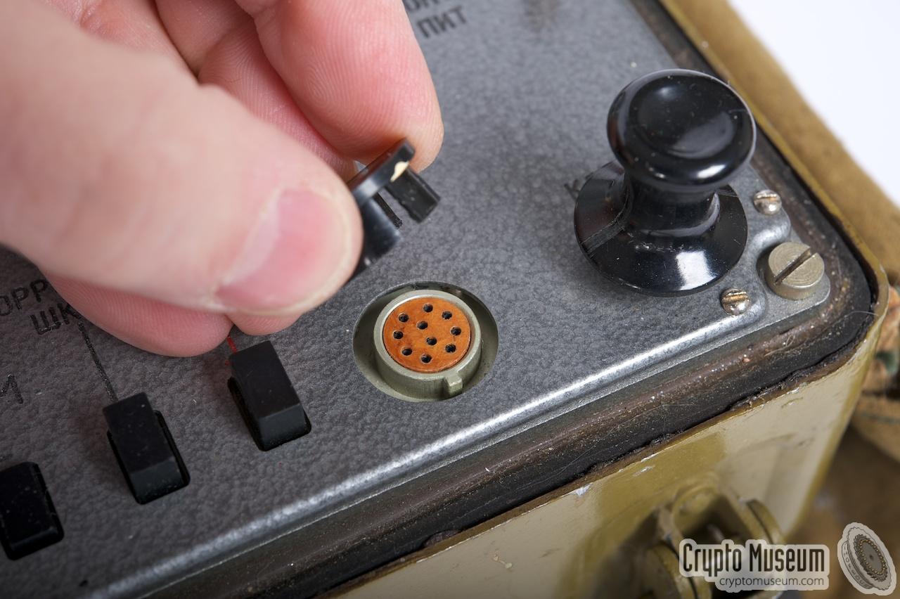
To the right of the switch is a 5A fuse that is used for protection
of the internal battery.
The small switch at the far right can be
used to check the battery voltage. When pressed, the small meter at the
top right of the transmitter will show the actual battery voltage.
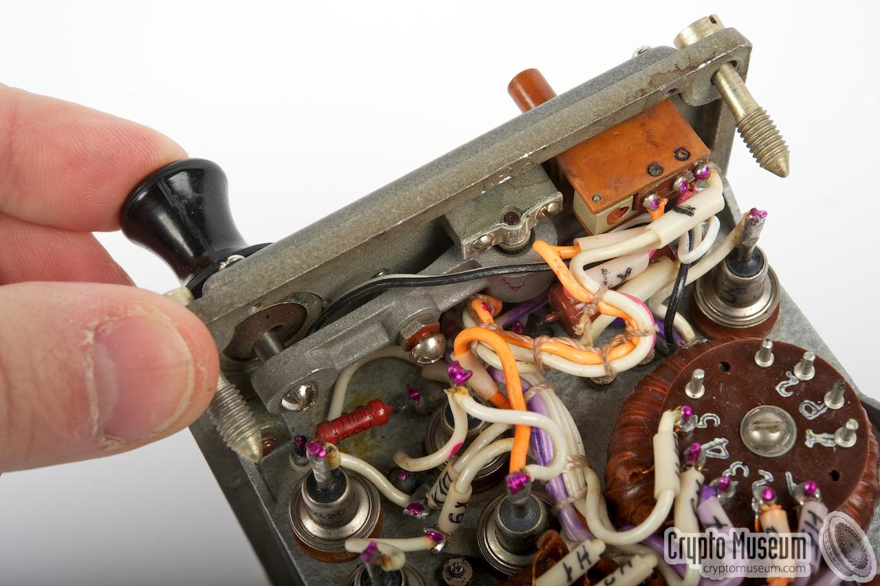
At the bottom right is an internal morse key
that can be used to manually send messages in
morse code, without
using the burst encoder. To its left is a 10-pin socket for
connection of an external key.
➤ Pinout
|
|
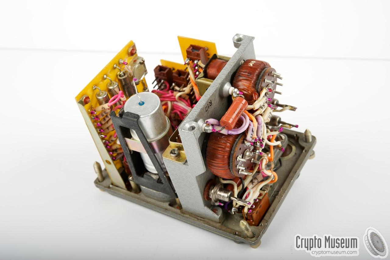
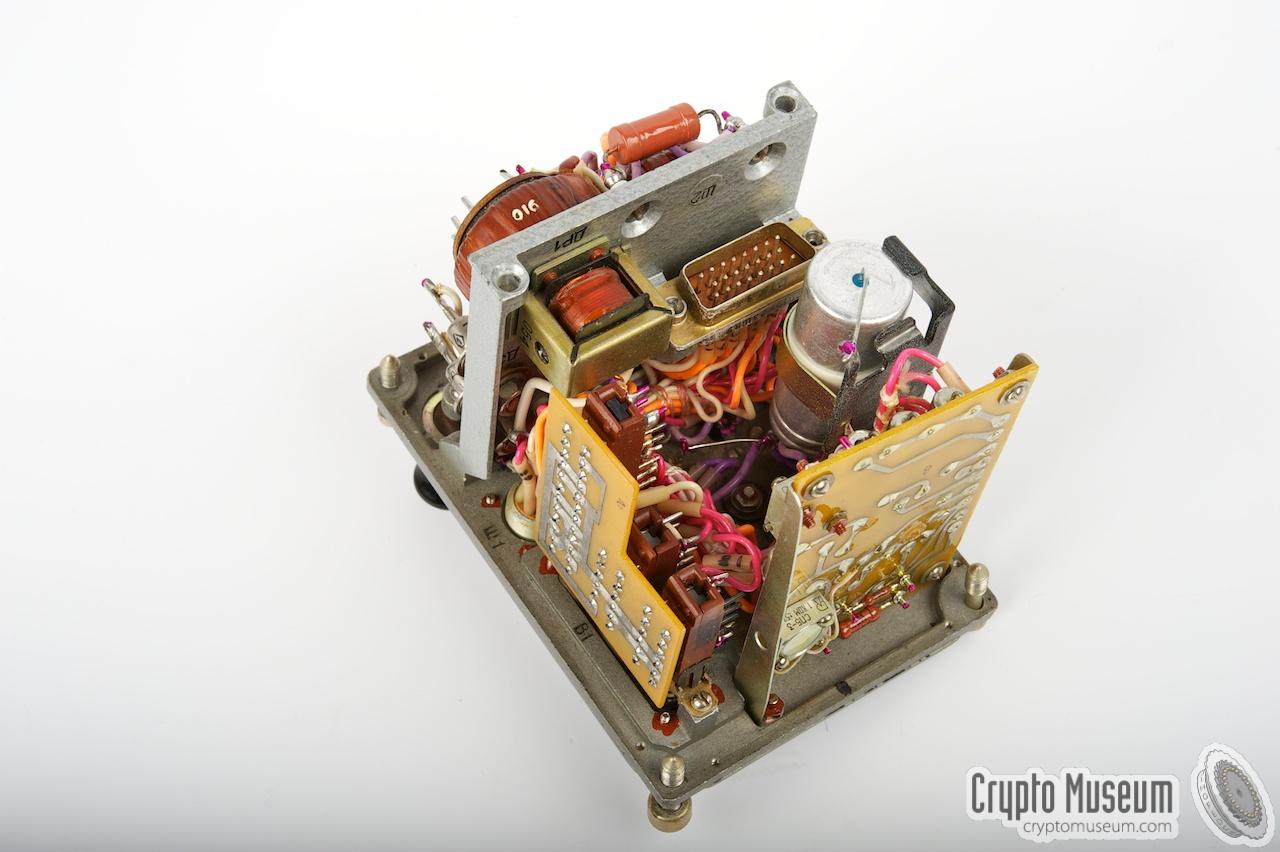
The transmitter (block 1) is located in the top right. It is a very
complicated but very clever combination of 3 more or less identical
frequency units (VFOs) that are mixed in such a way that the full range
between 1500 kHz and 13.499 MHz can be used with an accuracy of ± 500 Hz.
All the necessary internal frequencies are derived from a single 12 MHz
crystal oscillator [A].
|
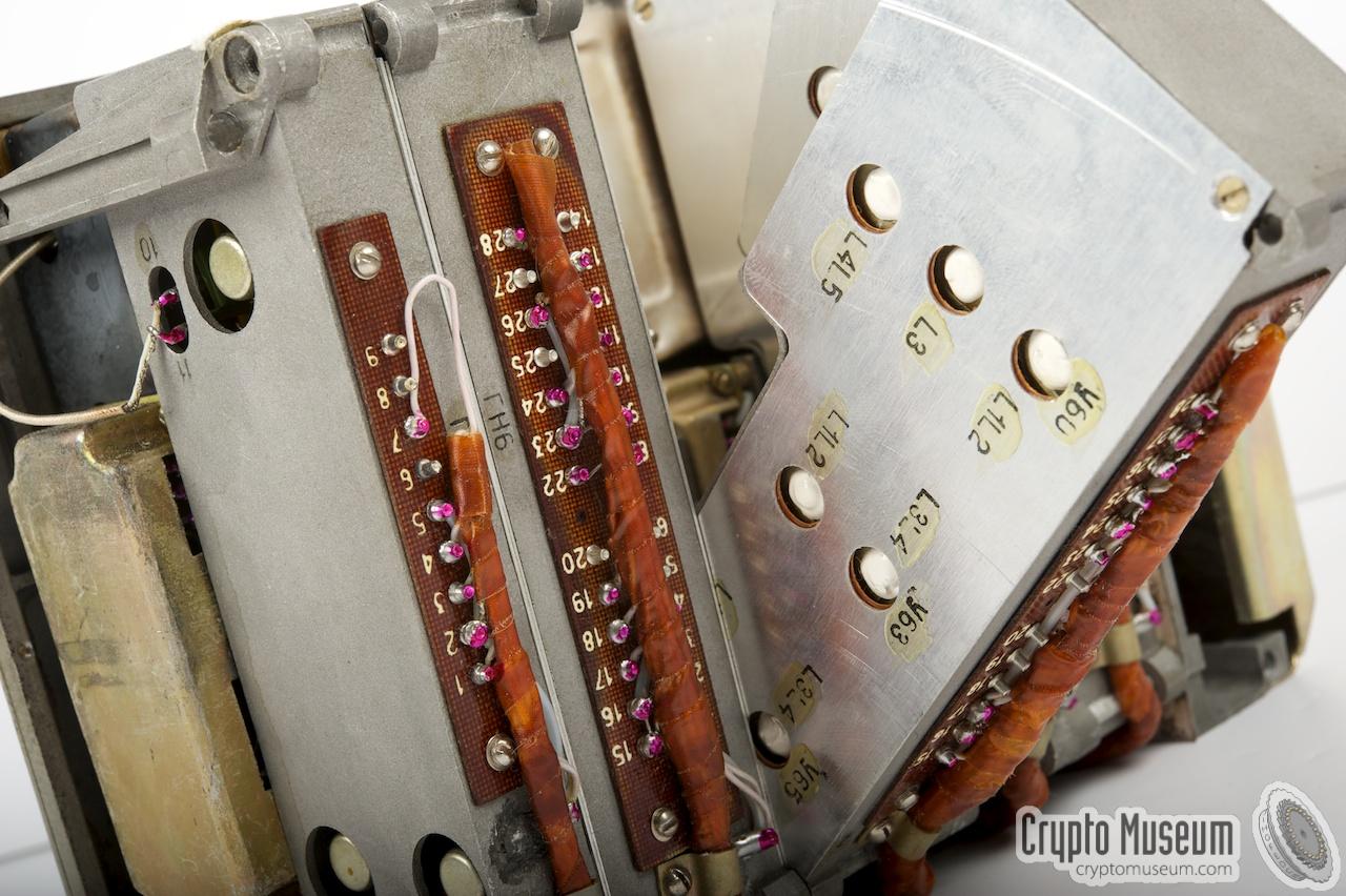
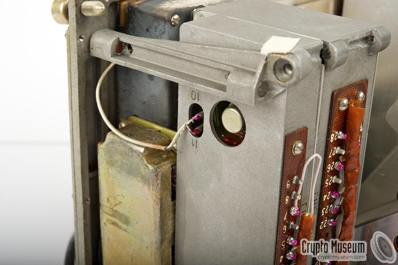
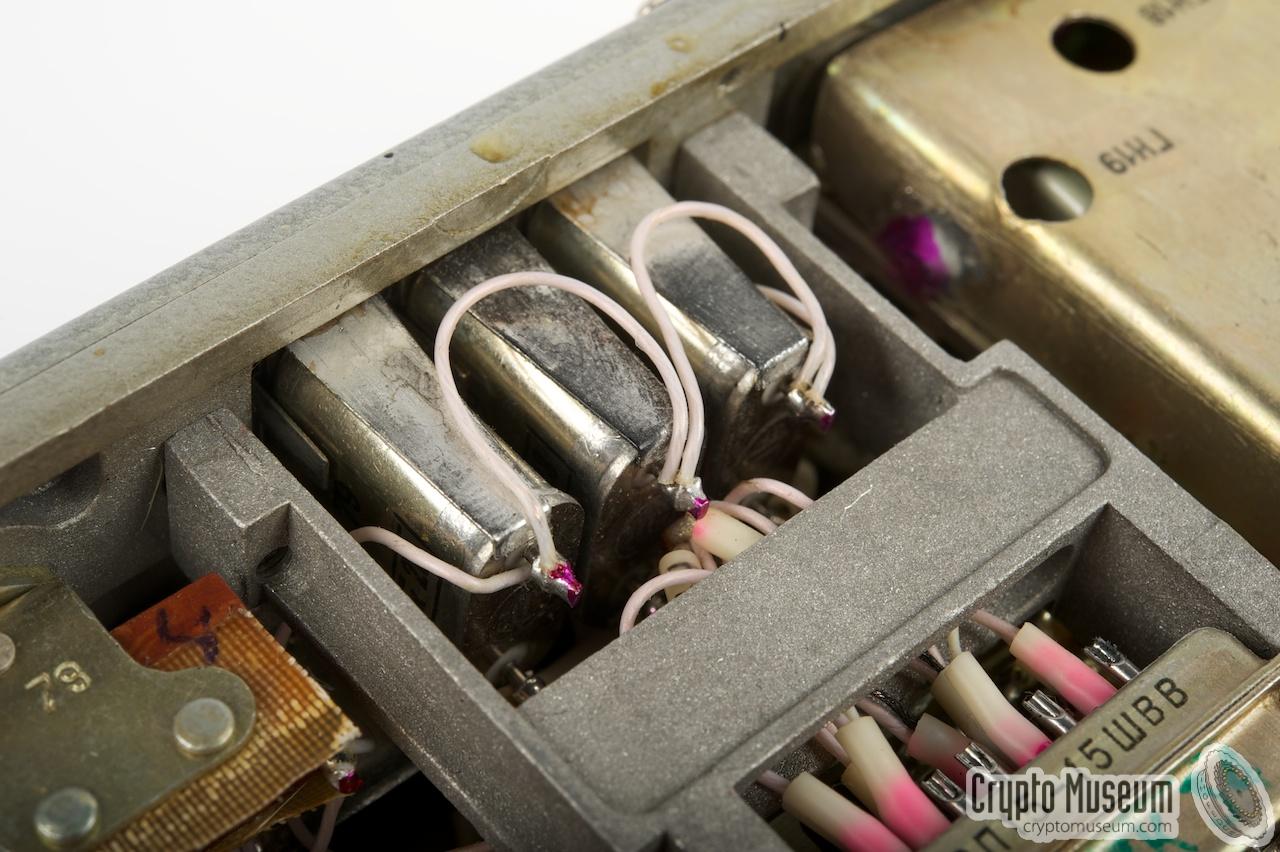
The image on the right shows the transmitter once it is removed from
the chassis. Each of the functional blocks
is housed in its own shielded
case, most of which are purpose-built die-cast aluminium blocks.
The blocks are mounted on an axle in such a way that they can easily
be 'turned' out of the way when servicing the unit.
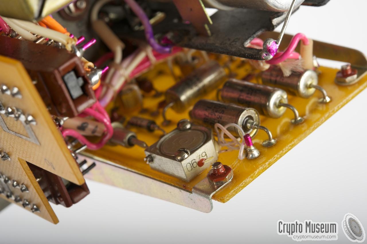
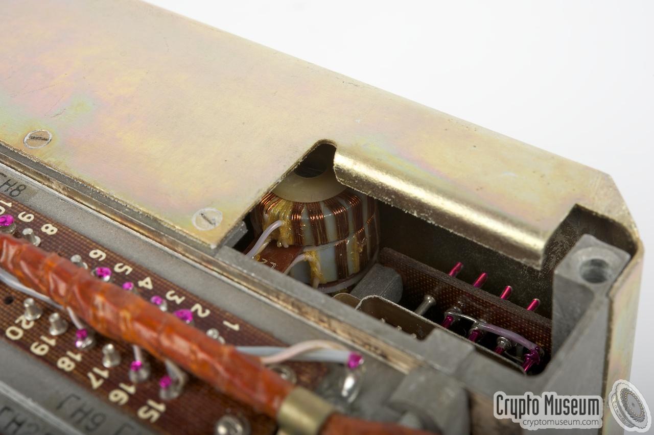
The images at the bottom of this section give a good impression of the
build quality of the transmitter. Behind each of the three frequency
dials is an adjustable capacitor that is
'trimmed' mechanically in order to make the scale linear.
|
|
|
The transmitter circuit is extremely complex. In order to make it
more comprehensible, we've divided it into a number of simpler
block diagrams. Let's first have a look at the main quartz-controlled
12 MHz oscillator. After buffering the 12 MHz signal, it is divided
several times. All intermediate frequencies are distributed throughout
the transmitter and are used at various places. At the far right is
the calibrator that produces a 500 kHz signal for the
receiver (block 3)
and an combined 20/100 kHz signal for the transmitter (press the
calibrator switch on block 2).
The actual transmitter consists of three independent VFOs that each
produce a carefully worked out frequency range. VFO-1 controls the
output frequency x1000. It is fed by a 500 kHz signal and
produces frequencies in the range 17.5 - 29 MHz. The two other VFOs
(2 and 3) are driven by a 20/100 kHz signal and produce lower frequencies
in the range 2 - 3 MHz.
The block diagram above shows the frequency range of each VFO (in red).
At the bottom of the diagram are four mixers that combine the outputs
from the three VFOs with the 1 MHz and 12 MHz signals from the main
oscillator. Finally, a low-pass filter (LPF) is used to ensure that
only frequencies in the range 1.5 - 13.499 MHz are used. Behind the filter
is the Power Amplifier (PA) and the Antenna Matcher. The connections
at the right are the antenna (A) and counterpoise (C).
Note that the frequency from VFO-3 is first divided by 20 before it
is applied to the first mixer. Immediately behind the divider is a
phase shifter that is used to modulate the morse signal from the
burst encoder when Phase-Modulation is selected (F1).
Now lets look at the VFO in more detail.
The block diagram below shows a single VFO, which is
in fact an analogue PLL:
The reference signal is entered on the left, whilst the manually
adjusted free-running oscillator is at the right. Both signals are
compared in a phase detector that drives a DC Amplifier,
followed by a Proportional Integrating Filter and finally a Voltage
Amplifier that applies a correction signal to the free-running oscillator.
Once the frequency scale is near a frequency that is a multiple of the
reference signal, the PLL locks-in and the indicator light is driven
by the DC amplifier.
|
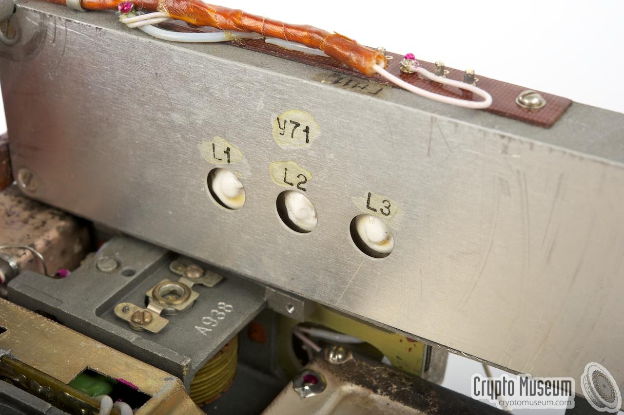
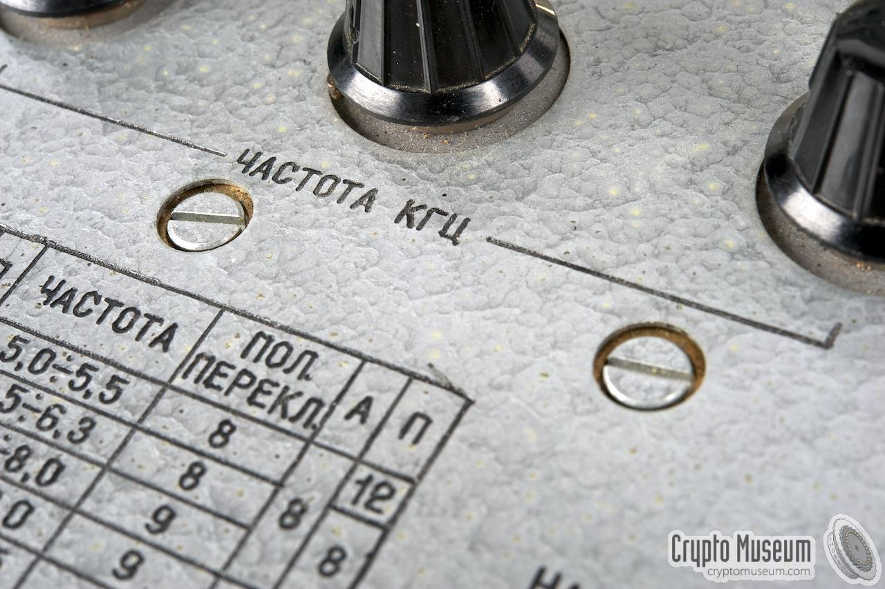
The image on the right shows scale calibration in progress.
The calibrator is turned on (middle button on the PSU) and the dials
are each set to a marker position.
The indicator lights above the scales should then be lit.
In case a lamp is not lit, adjust the dial until it does.
Then adjust the hairlines with the two big screws
below the dials.
Once the radio has been sufficiently warmed up (i.e. after approx. 10 minutes)
and the scales are calibrated, any frequency can be adjusted with an accuracy
of ± 500 Hz. The transmitter produces an HF output power of approx. 10 W.
|
|
|
This is sufficient for a range between 150 and 1200 km, depending on the
antenna, the time of the day and the frequency in use. The radio can
therefore be classed as medium-range. It can be operated in ambient
temperatures between -20°C and +40°C and a humidity of 98% (at 35°C).
Burst messages are usually sent in groups of 5 digits.
When used with Amplitude Modulation (AM) the radio can send approx. 12
such groups per minute. However, when using Phase Modulation (PM),
data can be sent at 167 groups per minute (select F1 on the burst encoder).
PM is achieved by injecting the morse signal directly into the
phase shifter of VFO-3 (see above).
|
|
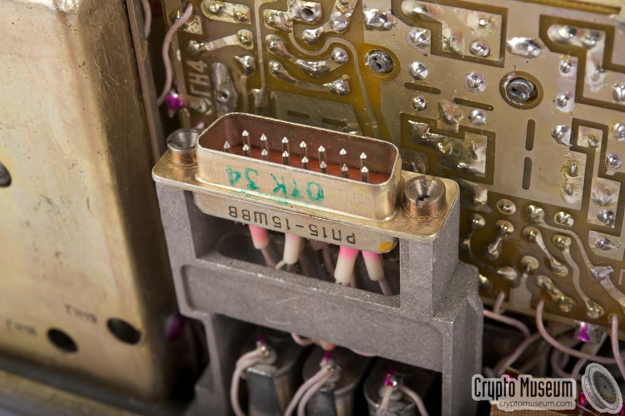
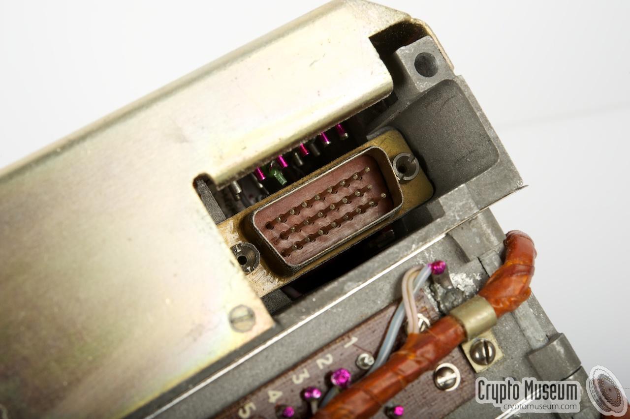
The Receiver (block 3) is a complete self-contained unit.
It is connected to the fixed wiring of the chassis by means of a
DB15 connector through which all power,
control and HF-signals are supplied.
The individual circuits are each built into
their own metal cases, packed
together as one compact modular unit that can easily be replaced.
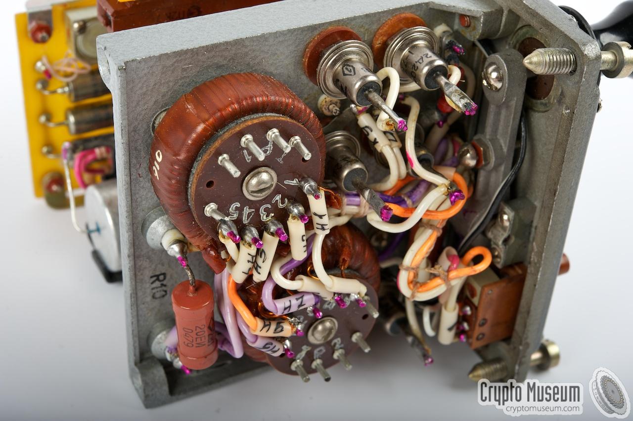
The receiver is a three-stage superheterodyne design with 190 fixed
crystal-controlled channels, as shown in the block diagram below [A].
|
On the front panel are two channel selectors
(marked I and II), plus a two-position switch (III) that allows the first
channel selector (I) to choose between two
banks of crystals (1 and 2).
The same selector (I) also controls the pre-selection filter of the
antenna input amplifier.
The 2nd IF consists of another bank of crystals,
controlled by the other selector (II). This results in a 2nd IF frequency
of 501.7 kHz. Finally, the 3rd stage, adjustable with a capacitor (TONE)
converts the signal into audible LF frequencies that are amplified to
headphones level.
|
|
|
Below, the simplified block diagram of the receiver is shown. The first
functional block is shown here as a band-pass filter, but it is in fact
a two stage MOSFET-based pre-amplifier with a series of calibrated
pre-selection filters, in order to obtain the best possible selectivity.
The first channel selector (I) is a
quite complex construction consisting of a
10-position 5-deck rotary switch amidst the three circuits it is
connected to. The second selector is much simpler.
A 500 kHz calibration signal from the transmitter can be injected at the
3rd stage, so that the TONE adjustment can be zeroized. Furthermore,
an audible tone from the burst encoder is injected directly in the LF
output stage. It can be used to monitor any outgoing morse signal.
|
|
|
Analogue Burst Encoder
wanted item
|
|
|
|
The initial version of the R-394K had an analogue tape-based burst
encoder in the leftmost position. It allowed pre-recorded (encrypted)
numerical messages to be played back at high speed in order to minimize
the risk of interception and detection. A spare cassette was supplied
with the radio and was stored inside a metal box that was
integrated with the top lid of the case.
|
The leftmost unit consists of a blank panel, with a rectangular 'blob'
in the middle. The blob is actually a lid that can be opened.
Below the lid is the metal tape cartridge, which is quite similar
to the one used with the R-353 spy radio.
The image on the right shows the transparent plastic cassette with the
metal tape, that is reveiled when the lid is opened. The tape itself
is perforated with square sprocket holes that are
driven by a cog-wheel inside the tape player.
It is unclear at present, how coded messages are recorded on the tape
(internal or external).
|
|
|
The photographs of the earlier R-394K are kindly supplied by Italian
collector Antiono Fucci
[2].
More information can be found on
his site.
At present, we have no full documentation of the R-394K (only a partial
manual). If you can supply additional details, please contact us.
Furthermore, we are still looking for this model so that it can be
added to our collection. — Wanted item —
|
|
Sometime in the mid-1980s a digital burst encoder was introduced.
It fits the leftmost slot and offers a plug-in replacement for the ageing
analogue tape-based burst encoder (see above). The new encoder is
functionally identical to the integrated burst encoder of the later
R-394KM.
|
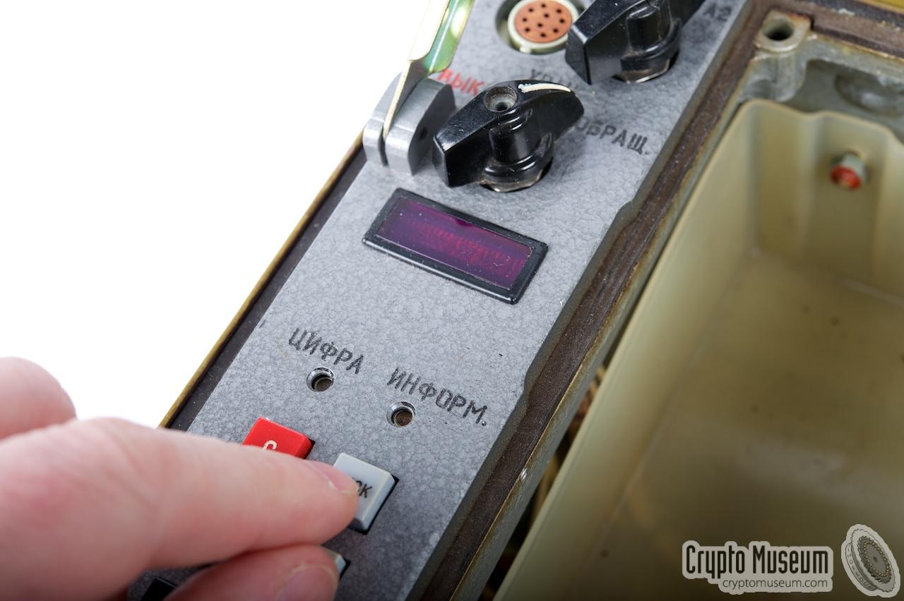
The burst encoder consists of a red 5-digit 7-segment LED readout,
10 push-buttons and two red LEDs.
It is also similar in operation to the external burst encoder that was
supplied with the post Cold War Severok-K spy radio.
At present, the digital burst encoder in our R-394K is not working as
parts of it have been removed as part of the demilitarization process.
We hope that it will be possible to restore the original functionality
in due course. When this happens, we will provide a full operational description
of this unit.
|
|
|
For the time being, please refer to the built-in digital burst encoder
of the R-394KM.
|
|
The R-394K was usually supplied in a large wooden box, complete with a number
of accessories, spare parts and full documentation. At present it is not exactly
known which parts were supplied and no complete kit has been found to date.
For the time being, we have to rely on the items listed in the manual.
|
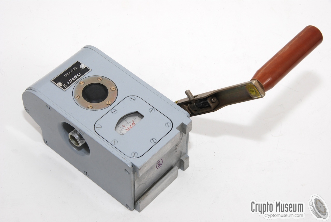
According to the manual [A], a separate hand-operated power generator
was supplied in order to charge the batteries in the field whenever no
mains power was available. Charging the batteries is not an easy task and
takes several hours, for just a few minutes of operation.
The generator is identical to the generators supplied with other
Russian spy radios.
|
|
|
|
Almost any type of headset can be used with the R-394KM.
In most cases, a common USSR military headset was supplied, with rubber ear
pads and elastic head bands. Such headsets are commonly used with military
radio sets in tanks etc. Headsets are connected to the two-pin socket on
the left of the front panel of the radio.
|
|
|
|
The antenna is usually stored inside a cavas packet to the right of the radio.
Depending on the way the radio is used, a second antenna might be needed as a
counterpoise. The second antenna (see the images below) can be stored in the same
pocket.
|
|
|
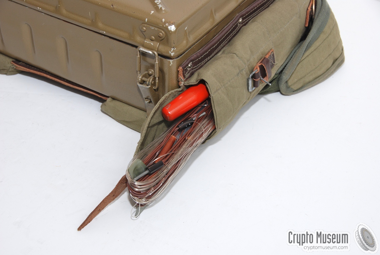
In order to setup the antenna as required, a light-weight telescopic glass
fibre mast is supplied. It allows the antenna wire to be mounted free from
obstacles and the earth. A ground pin is supplied to prevent the mast from
sliding away.
The mast and the ground pin are stored inside a canvas bag that can be strapped
to the radio or the canvas raincoat (see below).
|
|
|
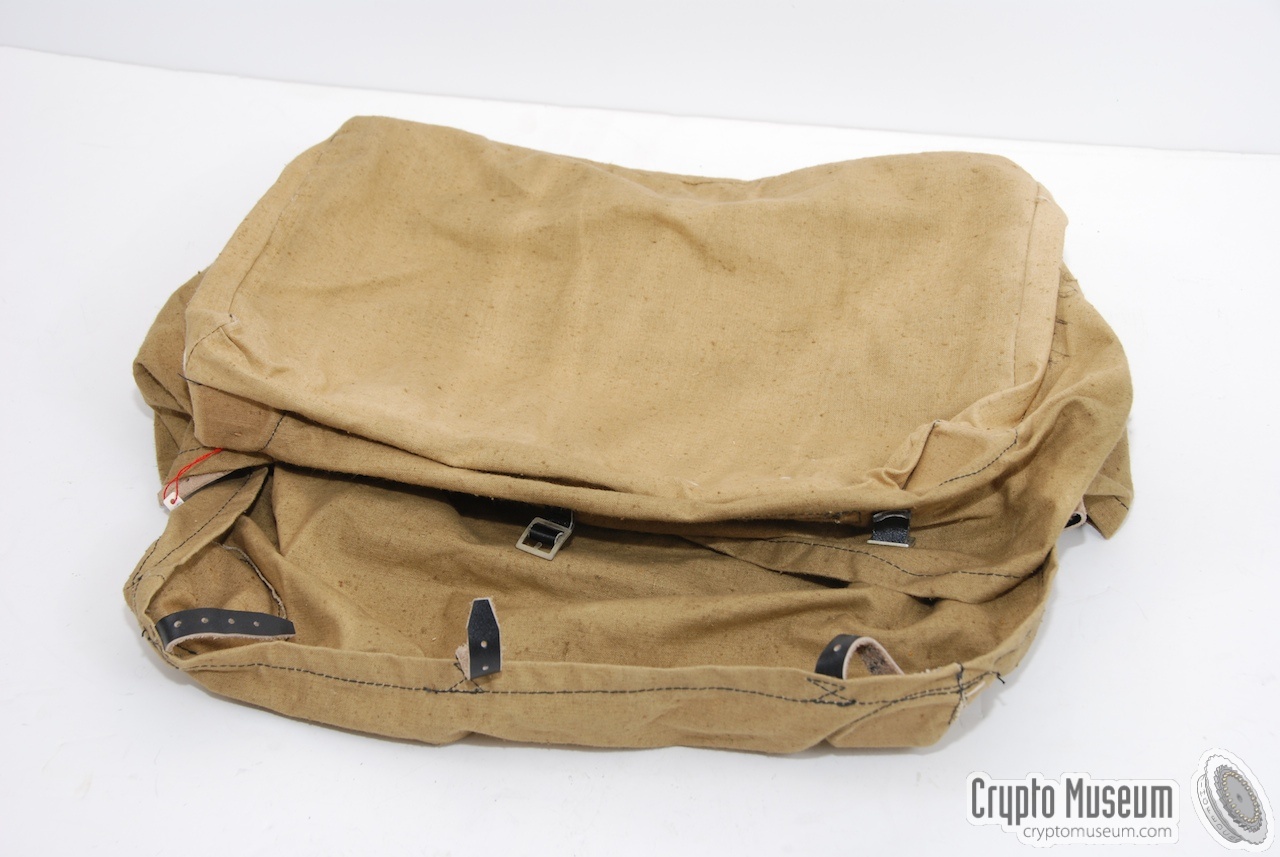
The radio is already painted in the usual Russian 'sand colour'
camouflage tint and has suitable padding at the bottom to allow the radio
to be carried on the back of the radio operator.
The lid of the unit is firmly closed with clamps and a gasket, to protect
the radio against dirt and water. Further camouflage is possible by fitting the
canvas raincoat shown on the right.
|
|
|
A set of spare fuses and lamps is stored inside a
small metal box that is fitted inside the
top right corver of the top lid.
The fuses are all 5A types of typical russian size.
They are used by the PSU (block 4).
The lamps are spares for the indicator lights above the
three frequency scales of the transmitter.
The image on the right shows the spares box with its lid open.
At the top left (inside the box) is a piece of insulating
tape that can be used for small repairs.
|
|
|
|
A complete R-394K radio station comes with an an extensive set of
documents that are usually stored inside the large wooden storage box.
The documents include the operator's manual and full circuit diagrams
of the analog and digital parts. Some of the books are marked 'Secret'.
|
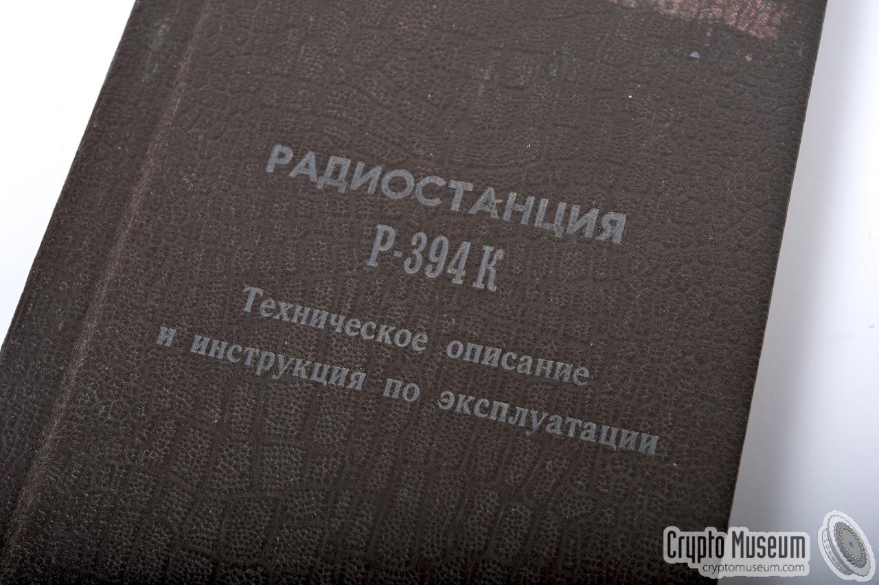
Unfortunately, most of the original documention has been lost or
has deliberately been destroyed by the authorities.
For the R-394K featured on this page, we only have a partly complete
manual available. The manual features the earlier (tape-based) model.
No description of the digital burst encoder has been found to date.
The image on the right shows our current manual.
The text СЕКРЕТНО (Secret) has been removed from the front cover and approx.
20 pages and circuit diagrams have been
ripped out as part of the
demilitarization process.
|
|
|
You can help us by supplying a complete manual,
or a copy, and any other additional documentation, information or items.
Any contribution is most appreciated.
|
To the left of the morse key is a 10-pin expansion connector
with the following pin-out:
An external morse key can be connected to this socket between KEY and GND.
The socket provides a stabilized +8V for the external morse generator
(early model) and the raw +12V battery voltage for any other device.
The PSU also produces a stabilized 25V for the transmitter power
amplifier (PA). When in TX-mode, this voltage is also available on the
expansion socket.
|
WARNING —
Please note that the original manual is wrong about the pinning of this
connector. Furthermore, the pinning of the same socket on the later
R-394KM is completely different. A device that is designed for
one model will get damaged when connected to the other one!
So, be careful.
Device Analogue spy radio set Purpose Special Forces (SF), reconnaissance, border patrol Origin USSR Year 1975 Frequency 1.5-13.5 MHz Steps TX: 1 kHz, RX: 190 fixed channels Accuracy 500 kHz VFO Analogue PLL Modulation CW, MCW (A2) 1 , PM 1 Output 10W Distance 150 - 1200 km Burst AM: 12 groups/min 2, PM: 167 groups/min Power 12V internal battery Dimensions 340 x 235 x 13.2 mm
|
-
R-394D only.
-
Each group consists of 5 digits and a pause.
|
- Radio Station R-394K, Technical Manual (Russian)
Original manual of the R-394K. Incomplete (pages removed). Date unknown.
|
- Louis Meulstee, R-394KM
Wireless for the Warrier. Volume 4. September 2004. ISBN 0952063-36-0.
- Antonio Fucci, R-394K Transceiver
Website with photographs of the earlier R-394K.
Retrieved February 2012.
Photographs of earlier R-394K on this page used
with kind permission.
- Louis Meulstee, R-394K(D)
Wireless for the Warrier. Volume 4. Supplement Chapter 157.
January 2019.
|
|
|
|
Any links shown in red are currently unavailable.
If you like the information on this website, why not make a donation?
© Crypto Museum. Created: Wednesday 18 January 2012. Last changed: Monday, 16 May 2022 - 06:34 CET.
|
 |

|
|
|