|
|
|
|
|

|
|
DDR RFT RX OWVL Cold War BND CIA
DDR domestic MW/SW receiver · 1959
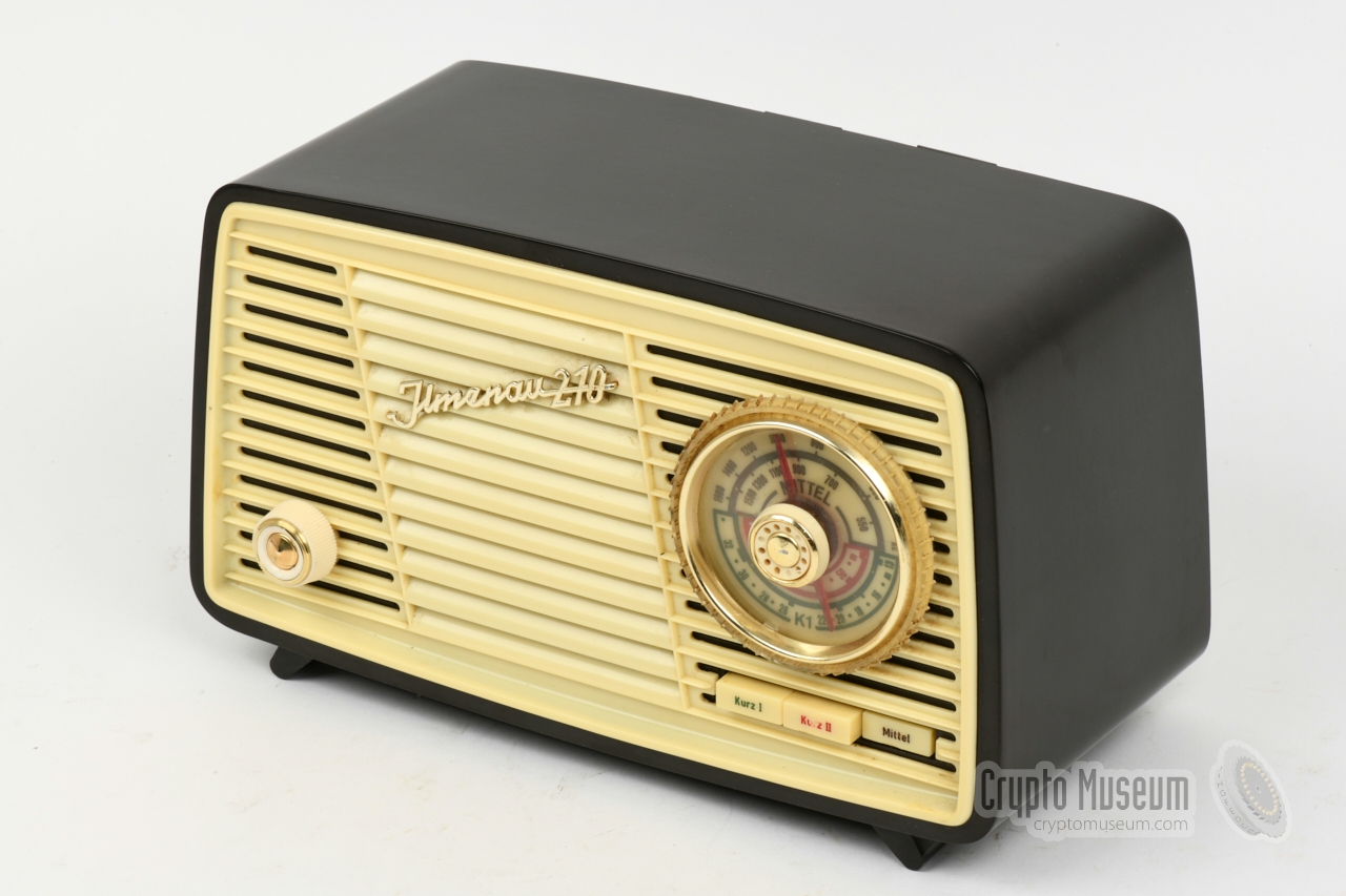
Ilmenau 210 was a domestic valve-based receiver
for the Medium Wave (MW) and Short Wave (SW) radio bands,
manufactured from 1959 to 1962 by VEB
Stern-Radio Sonneberg in Köppelsdorf (Thüringen)
in the former DDR (East-Germany). As it was one of the few
radios in the DDR that could receive the 3-4 MHz band, it was selected by
Western intelligence agencies like the CIA,
for use by its agents operating inside the DDR,
for the reception of Numbers Stations (OWVL) [5].
|
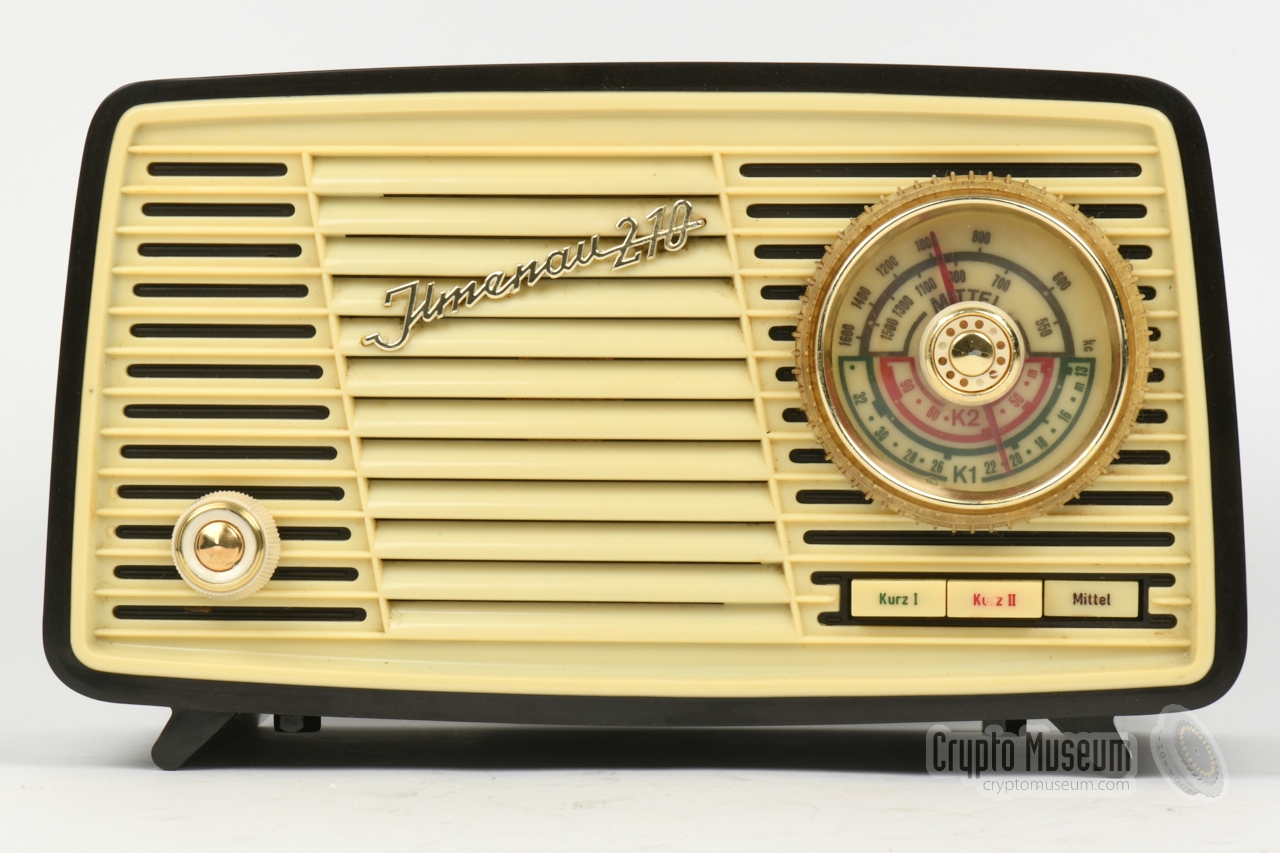
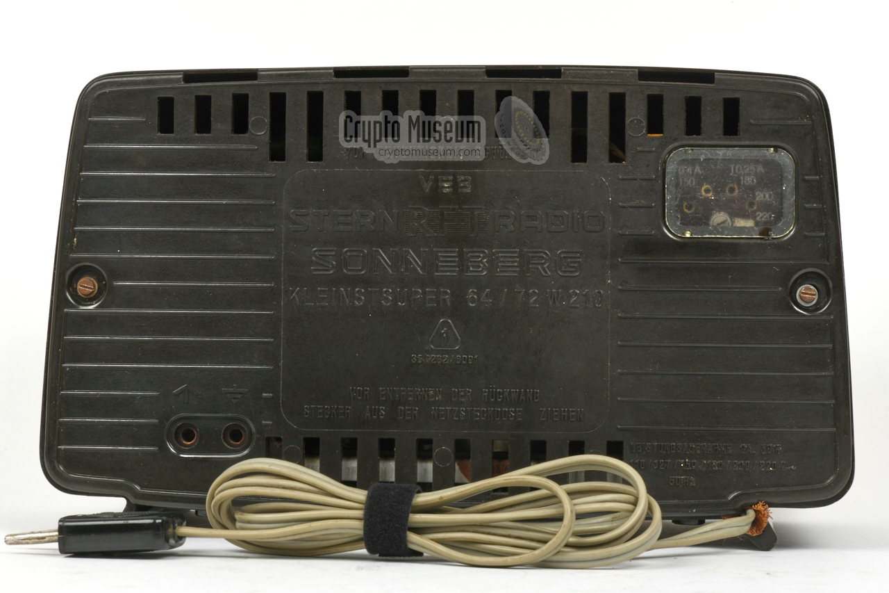
The radio is housed in a bakelite enclosure, and has plastic
front and rear
panels. At the front is the volume knob – also the ON/OFF switch –
the speaker, the tuning dial and a
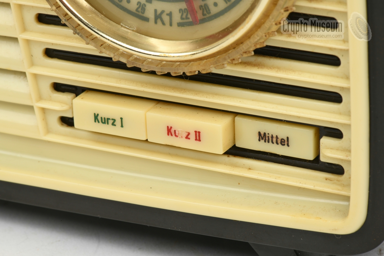
three-button band selector marked
Kurz I (SW 1), Kurz II (SW 2) and Mittel (MW).
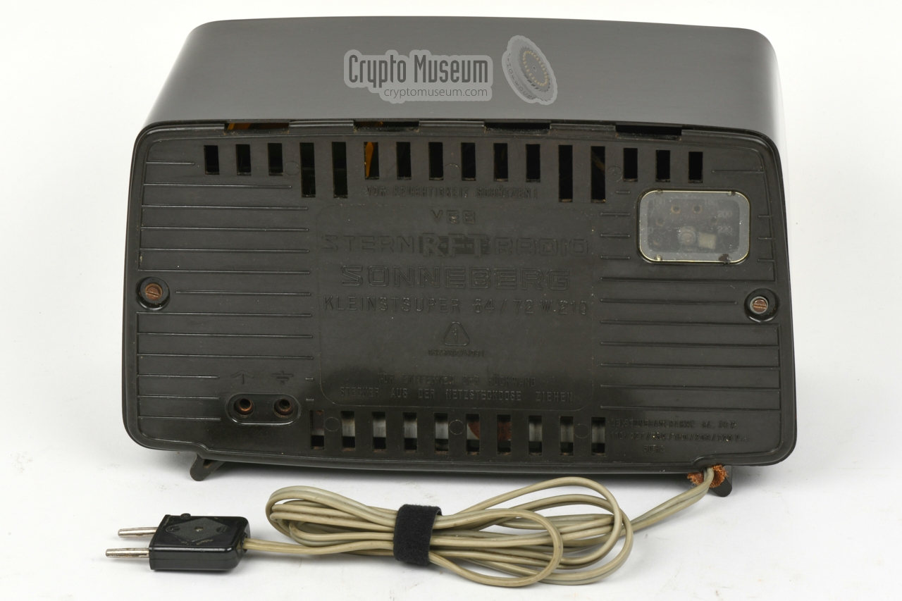
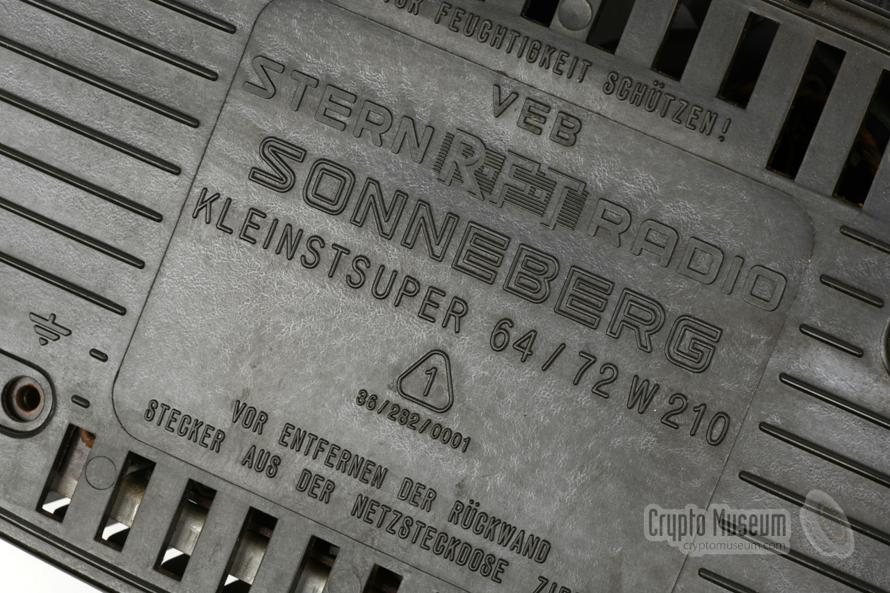
According to the rear panel,
it was also known as the Kleinstsuper 1 64/72 W 210.
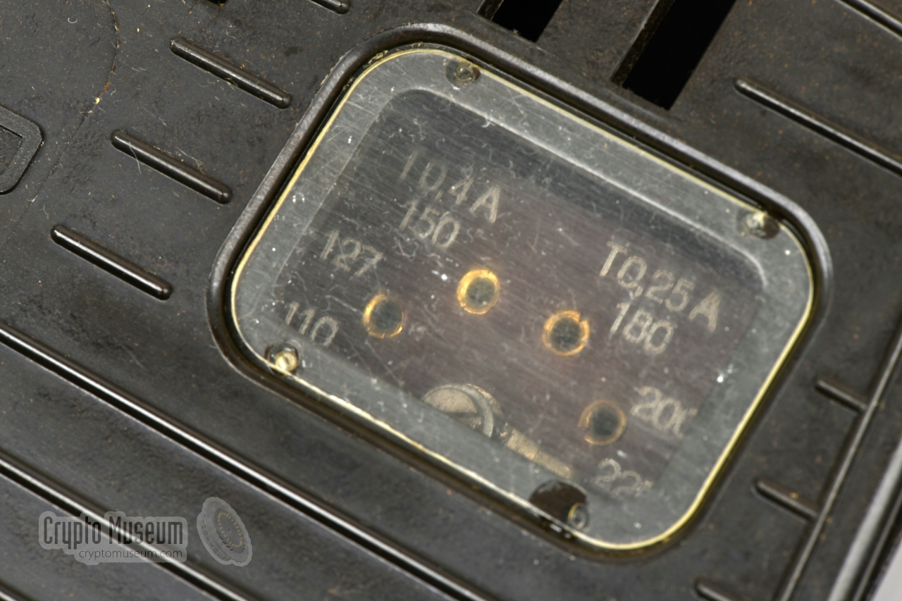
The radio can be powered by a mains AC voltage between 110 and 220V,
selectable with a dealer-configurable wire link
that is located behind a transparent plastic window
in the rear panel. It requires the plastic back panel to be removed.
|
|
|
Ilmenau 210 was available around 1960 for a price of
180 DDM, which was a substantial amount for the average
DDR citizen at the time. It was often used as a second radio in the
kitchen or the office. It is very similar to the Ilmenau 480 —
manufactured on the same production line — which differed only in
frequency range (SW, LW, MW). As Ilmenau 210 covered the
3-4 MHz band, it was purchased by CIA agents on the local market,
which soon made the radio a suspicious item [5].
Ilmenau 210 was in production until 1962, after which it was gradually
replaced by all-transistor models, like the
portable Sternchen,
which were no longer suitable for reception of the 3-4 MHz band. 2
This prompted the German intelligence service BND to develop
an external SW-converter.
|
 |
-
Kleinstsuper = miniature superheterodyne receiver.
-
There were other radio receivers on the market in the DDR that were
capable of receiving the SW band, but they were not suitable for
frequencies below 6 MHz, making them unsuitable for CIA/BND use.
|
WARNING —
It should be noted that the radio uses a so-called autotransformer [4],
as a result of which the chassis (and even the screw of the volume knob)
may carry the full 110V or 220V AC mains voltage,
which can potentially be lethal. For this reason, the four screws at the
bottom — used to hold the chassis inside the bakelite enclosure — have
plastic caps. For demonstrations, it is advised to use an isolation tranformer.
|
Ilmenau 210 is housed in a bakelite encosure with plastic front
and rear panels.
Its interior can be accessed by removing two screws at
the left and right edges of the rear panel,
after which the rear panel can
be taken off. This exposes the interior of the radio, as shown in the image
above.
|
Inside the enclosure is a metal frame, which is bolted to the bottom of the
bakelite enclosure by means of four screws with plastic heads. This is
necessary, as the device is powered by an autotransformer [4],
as a result of which the chassis may carry the
110V or 220V mains AC voltage.
Before removing the frame from the enclosure, it is necessary to remove
the volume knob – held in place by a single screw – and the tuning dial,
which is clamped. It has to be removed carefully,
as it might be binding to the
axle and the plastic scale may have become brittle over the years.
|
|
|
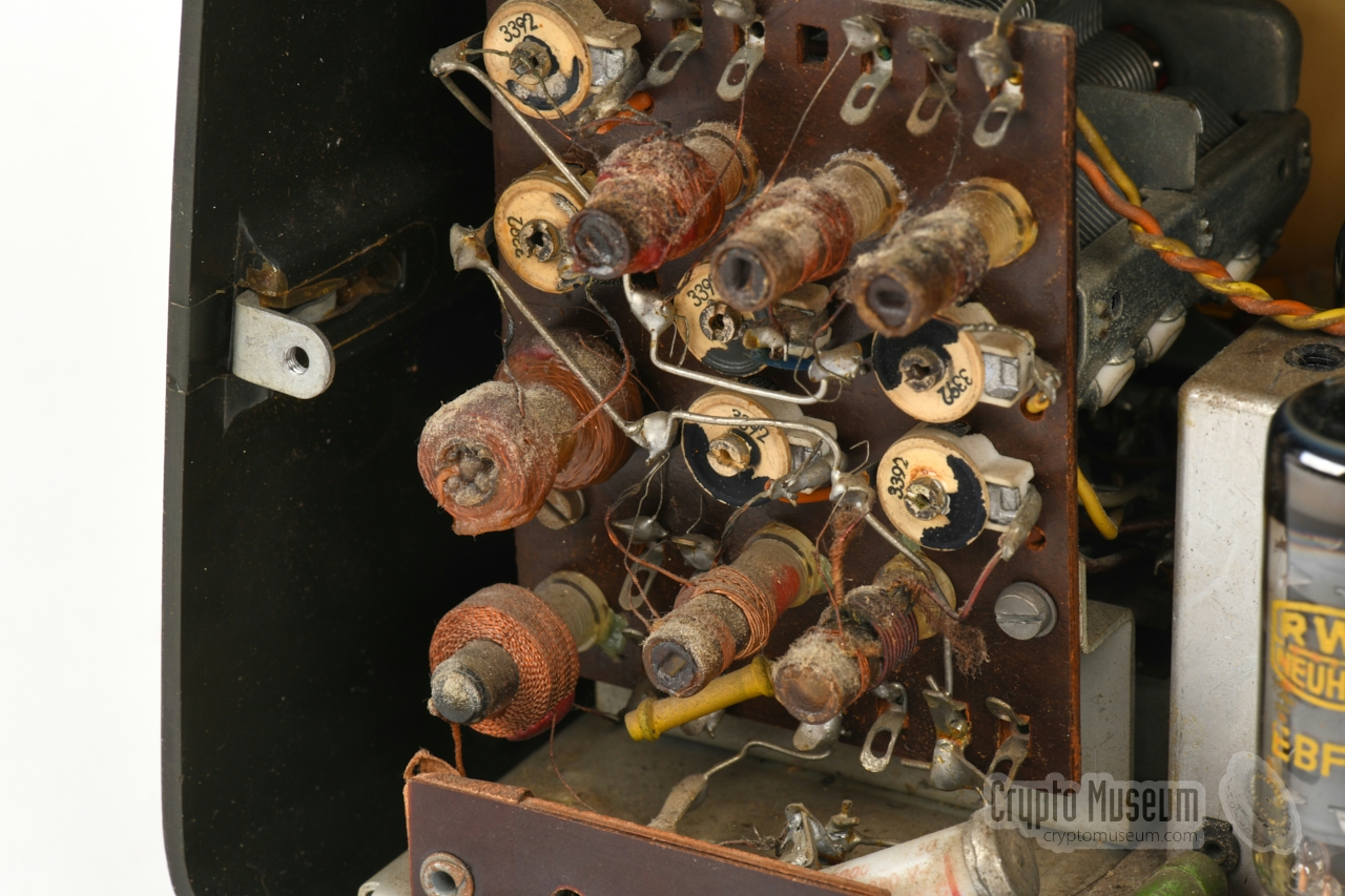
Once the knobs have been removed, the chassis can be removed from the
enclosure, leaving the speaker and the output transformer bolted to the
front panel. The circuits are built onto a printed circuit board (PCB)
that is fitted to the metal frame. At the left is a vertical PCB with
the tuned circuits of the 3 band filters.
Behind it, is a tuning capacitor with two sections moving in tandem.
At the right is a small
PCB with the mains AC voltage selector.
It is here set to 220V, which might be
too low for the 230V AC mains voltage in Europe. It may cause the
transformer to go into saturation, with results in overheating and eventually
irreparable damage to the transformer. It is advised to use an isolation
transformer, which also converts the 230V down to 220V or less.
|
Device Domestic radio receiver Model Ilmenau 210 Designator 64/72 W 210 - Kleinstsuper Manufacturer Stern-Radio Sonneberg (RFT-VEB) Year(s) 1959-1962 Users Citizens (DDR), CIA, BND Type Superheterodyne Modulation AM Bands 3 (see below) IF 473 kHz Circuits 6 Valves ECH81, EBF89, ECL81, EZ80 Power Mains AC 110V, 127V, 150V, 180V, 200V, 220V — 50/60 Hz Dimensions 270 × 160 × 135 mm Weight 2.7 kg Price 180 DDM
|
Mittel MW 510 - 1650 kHz Kurz I SW1 9 - 22 MHz Kurz II SW2 3.15 - 7.4 MHz
|
|
|
|
Any links shown in red are currently unavailable.
If you like the information on this website, why not make a donation?
© Crypto Museum. Created: Tuesday 06 October 2020. Last changed: Friday, 03 June 2022 - 05:35 CET.
|
|

|
|
|


