|
|
|
|
|

|
|
UK Phone Voice GPO Scrambler No. 710 → ← SA 5063/0
The SA5063/1 was used on a direct exchange or
PBX line,
or – with the SA5050 Auxiliary Unit – to let
up to three SA5063/1 units share a single Frequency Changer.
The primary difference with the SA5063/0 is the addition of extra
security switch contacts, so that other terminals wired in parallel
can not eavesdrop on the conversation.
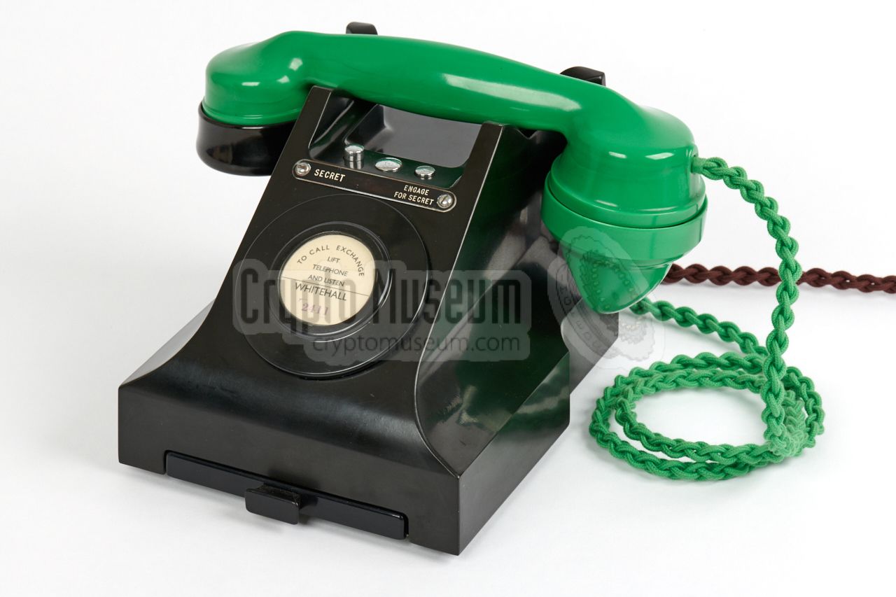
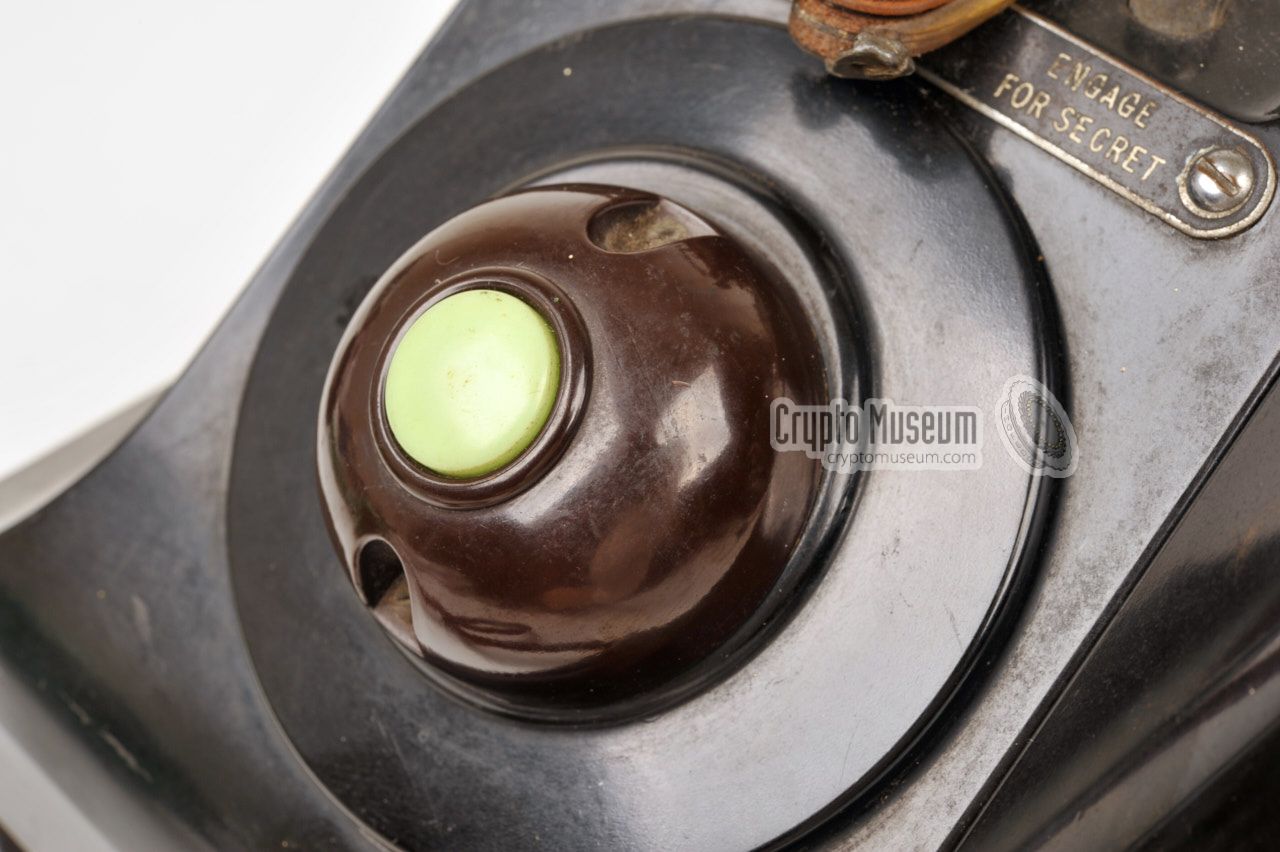
The SA5063/1 had two push-buttons, labelled SECRET and ENGAGE FOR
SECRET 2 but the latter (ENGAGE FOR SECRET) had no function if the
set was connected to a direct exchange line. These units can not
be fitted with a 3rd push-button. 3
|
|
|
 |
-
20-way box terminal (BT) with metal lid. Alternatively,
an 8-way BT20/8 could be used.
-
Later: SCRAMBLE and HOLD SCRAMBLER.
-
The 303/B key assembly
misses the plunger for that.
There is however record of a label marked PRIVATE - NORMAL - ENGAGE FOR
PRIVACY, which suggests that some phones did have a third button.
In such cases the unit had to be fitted with a
303A key assembly
and the centre button would have been used to release
the other two, without the need to place the handset in the cradle.
|
|
A scrambler system like the Frequency Changer, does not provide any
real protection against a professional eavesdropper. All the intercepting
party has to do, is reverse the speech spectrum once more to make the
conversation intelligible again. This was known by the UK's War Office,
of course,
but it was believed to be sufficiently secure against a casual eavesdropper,
such as the operator in a manually switched exchange, or a service
engineer working on the telephones lines.
|
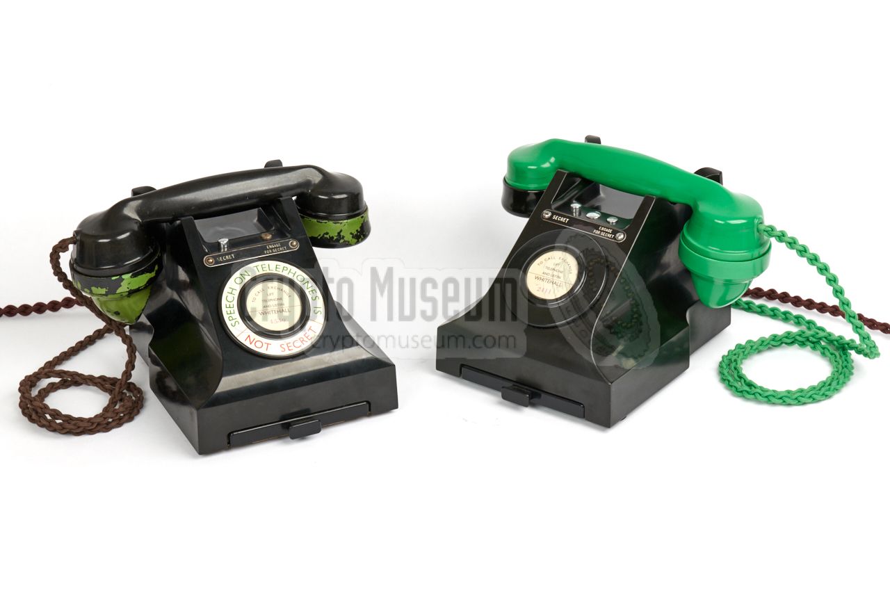
In order to discriminate scrambled telephone lines from regular
ones, circular labels were issued to mark a regular phone as insecure:
SPEECH ON TELEPHONES IS
NOT SECRET
These labels were fitted in the area around the dial or the blanking
panel. Although they were intended for regular phones, they sometimes
landed on scrambled phones as well. On the majority of scrambler phones
it was omitted however. The label on the phone in the image on the right
is therefore considered out of place.
|
|
|
Note that many 'scrambler phones' that are offered on auction sides
such as eBay, carry a circular label that is clearly a (bad) reproduction
of the original one. In many cases, a simple typeface like
'Helvetica' or 'Univers'
is used, whereas the original one was typeset in 'Gill-Sans'. If you
insist on having this label installed on your telephone, you may want to
download this reproduction [A].
|
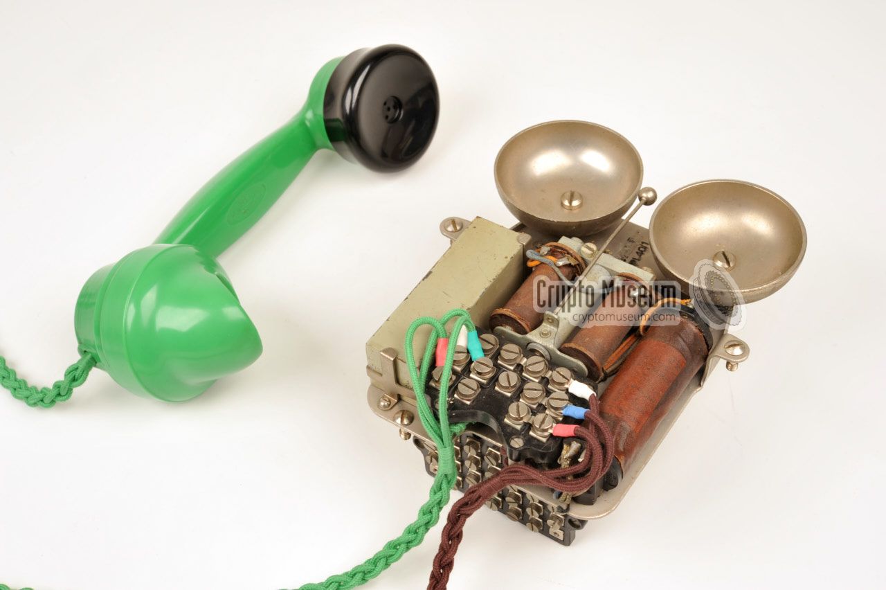
With the exception of the very early Frequency Changers – that were
equipped with a No. 162 — nearly
all wartime installations used a voice terminal that was based
on the chassis of Telephone No. 394 or 396, both members of
the 300-family
of GPO telephones that started life in 1937.
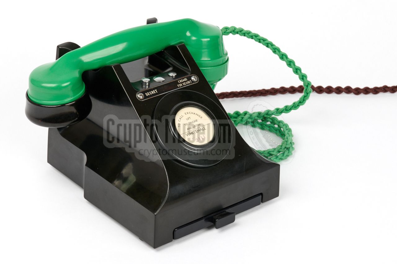
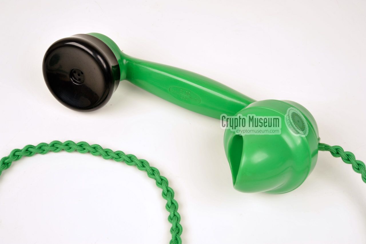
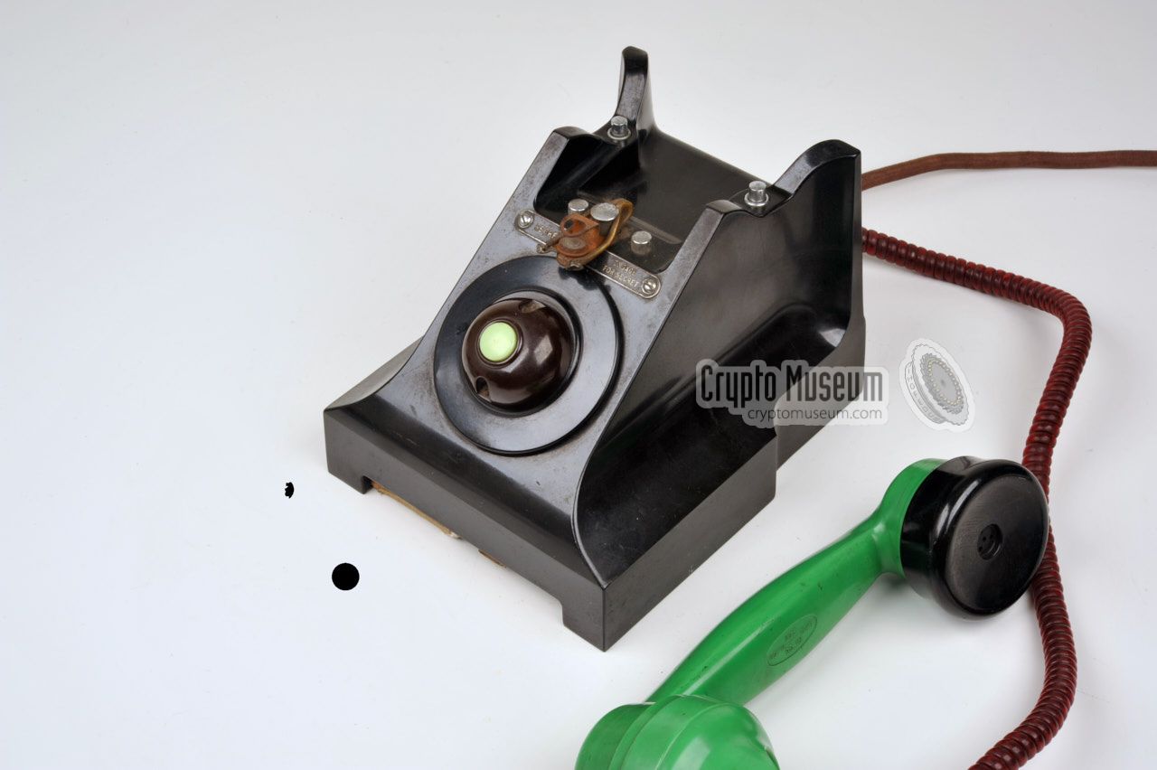
In all cases, the telephones were given a green handset, so that
the voice terminals
used with the Frequency Changers (scramblers) could
be distinguised from regular (unprotected) telephones.
The Jade Green version of bakelite handset No. 164
was used for this. The one at the right in the image above is of this
type. The same one was used with the earlier
Telephone No. 162.
In this case the receiver 1 has a black cap rather
than a green one, for which there was a good reason.
Standard 164 handsets were fitted with a receiver 2 that was considered
of insufficient quality for use with the scrambler system.
An engineering directive was therefore given that these should be
swapped for alternative ones, 3 but these were only
available in black bakelite for most of the war period.
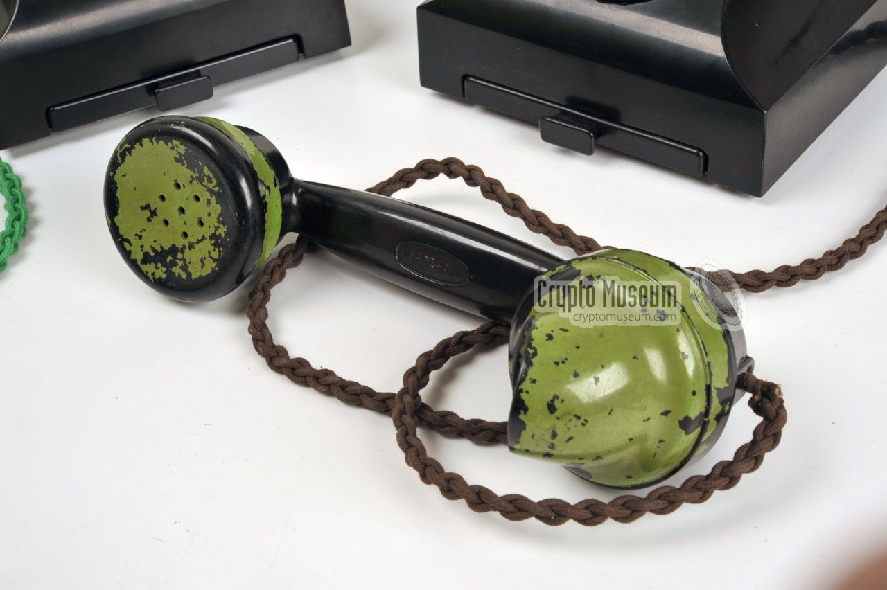
A 164 handset with a black receiver cap can also be spotted in the
photograph of the Cabinet War Rooms
at the top of this page, in which it is held by
Royal Navy Captain Richard Pim.
When green handsets were is short supply during the war, regular
black 164 handsets (or sometimes ivory as well)
were painted in a lime green colour that did
not match the colour of the Jade Green handsets. The leftmost
example in the image above is of this type. The braided cord of
the handset could be green or brown, whichever was available.
|
|
-
Also known as earpiece or speaker.
-
By default, Receiver No. 1L, Diaphragm No. 12, and Receiver
Cap No. 18 were installed on handset 164.
-
The replacement consisted of Receiver No. 2P,
Diaphragm No. 25 and Receiver Cap No. 23.
|
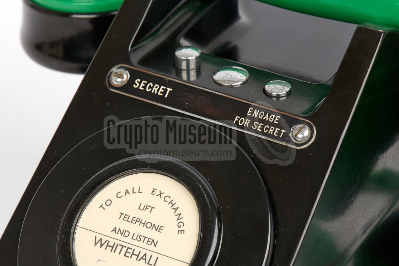
There are also different variants of the metal shield with the text
labels that is mounted just below the SECURE and CLEAR buttons. At least four
version have been spotted over the years, which are shown below. In all
cases, the leftmost button is used to go secure (secret, scramble),
whilst the rightmost button is used for clear speech
(normal, hold scrambler, engage for secret).
We believe the above label to be the eldest as it does not appear
in the 1952 list of labels that was used at the GPO.
Furthermore it is present on the phones in our collection that were
made in 1938 and 1940 respectively.
Other labels that are known to have been issued over the years are:
Depending on the configuration of the telephone set, the user requirements
and the presence or absence of a third button at the centre,
other arrangements and text labels may have existed. The labels could be
engraved or screen printed.
If it was screen printed, a condensed variant of the Gill-Sans typeface
was commonly used.
For a complete overview of the 27 different
text labels No. 252 & 253 that were available between 1952 and 1967,
please refer to list N620
[3].
➤ Overview of text labels
|
|
Although it was technically possible to fit a dial to a 394/396
telephone body, the standard issue was without one, as most installations
were used on manually switched networks during WWII. In that case the
circular hole at the front of the telephone set was covered
with Blanking Panel No. 3.
|
Furthermore, the British Government had its own private network
– completely separated from the public switched network – and
many of its users, including
Churchill, relied on an
assistent to set up a call via the exchange operator and initiate
a conversation, before handing it over to the user.
If the scrambler was used on networks with automatic exchanges,
or on a local PABX that had automatic exchange facilities,
the voice terminal could be fitted with a dial, so that
the user could select the extension number directly.
This is the case with the SA-5030 shown here.
|
|
|
In post-war systems, most voice terminals did have
a dial, as automatic exchanges had meanwhile become mainstream
in most countries. Nevertheless, the blind telephones sets (i.e. units
without a dial) remained in use in many installations, in which case
the line terminals of the Frequency Changer were commonly connected
in parallel to a regular telephone set (with dial).
➤ More about the SA-5030 with dial
|
Below is the internal wiring diagram of the
SA 5063/1 telephone set.
At the bottom right are the (A) and (B) terminals of the subscriber line.
Directly above it, is the wiring to the screw terminal of the Frequency
Changer 6x. The make-before-break (MBB) switches KA (1-4) are part of
the 303/A Key Unit
that is controlled with the 2 (or 3) push-buttons on top of the
telephone set.
They allow the telephone set to be used for plain as well as secure
calls. In secure mode, the speaker and microphone of the telephone's
No. 164 handset are routed via the Frequency Changer 6x.
During WWII, the dial armature was often omitted from the
SA 5063/0 and SA 5063/1 telephone sets,
as the British Government used a private telephone network
– completely separated from the public switched network –
that was patched manually. The diagram above is also applicable to
the SA 5030 and other
300-series telephones
that were modified for use with Frequency Changers.
|
|
Getting access to the interior of an SA50xx terminal is quite
straightforward. Loosen the four bolts at the corners of the bottom panel
(not the rubber feet) and take it away.
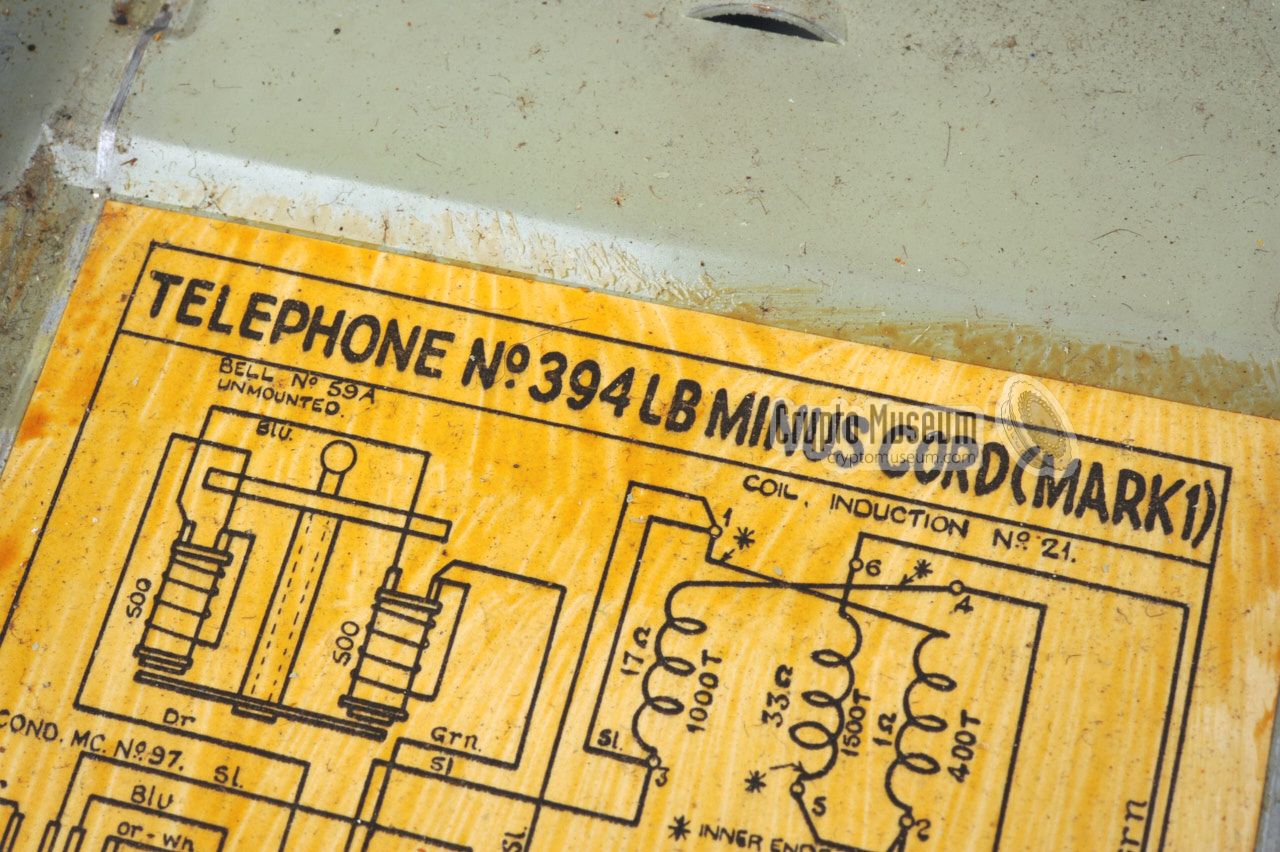
The bottom panel also holds the
small drawer. Note that a
circuit diagram should be present under the drawer.
|
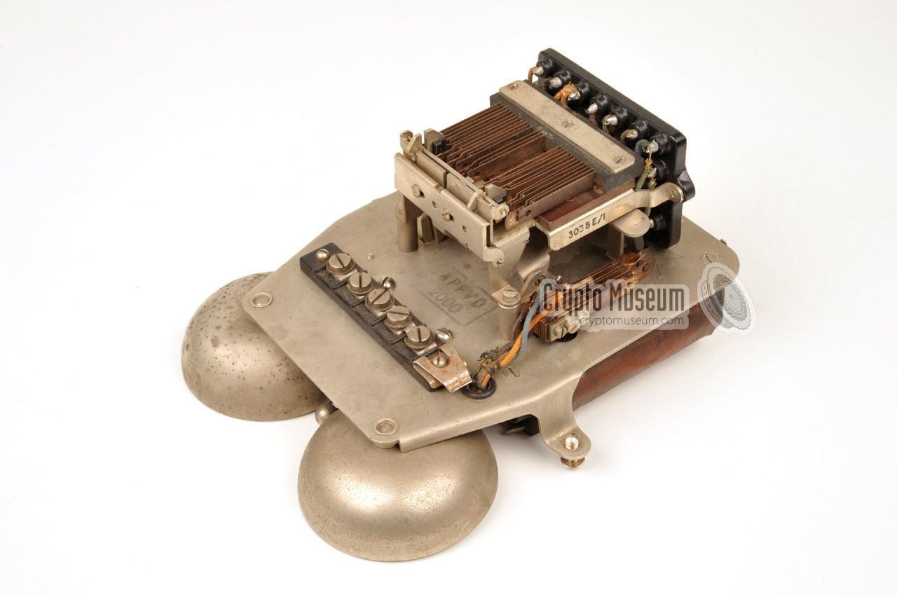
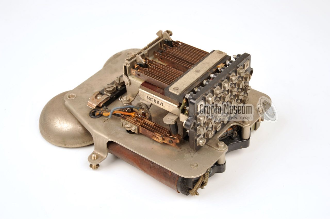
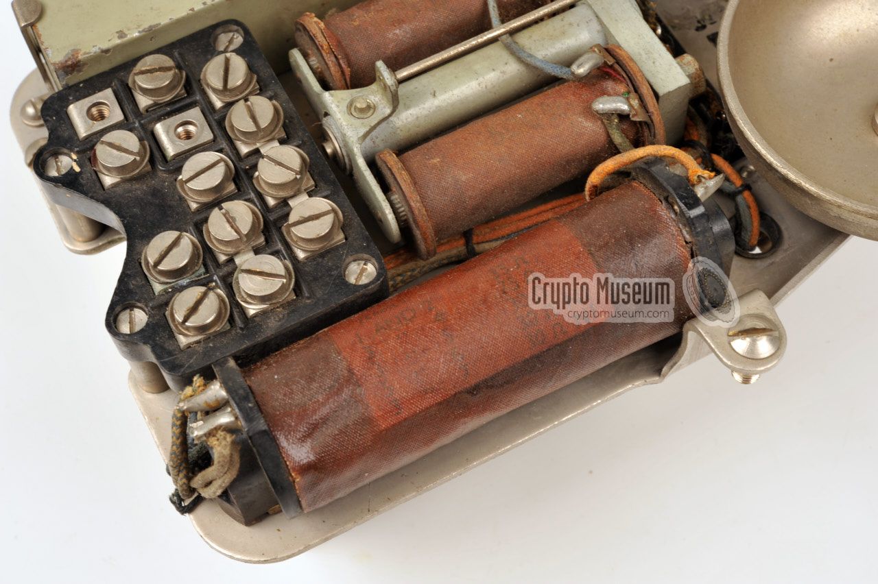
Inside the set is a metal chassis to which all internal parts
are mounted. Prominently visible towards the front is the
optional bell which takes up most of the space.
Apart from the bell, the bottom section also houses the
transformer,
a large capacitor
and a 13-point contact block
for connection of the handset and the outside line.
The chassis can be removed from the body of the telephone by loosening
three bolts: two at the sides and one towards the rear (behind the capacitor).
As most sets have no dial, there are no extra wires that
have to be disconnected.
|
|
|
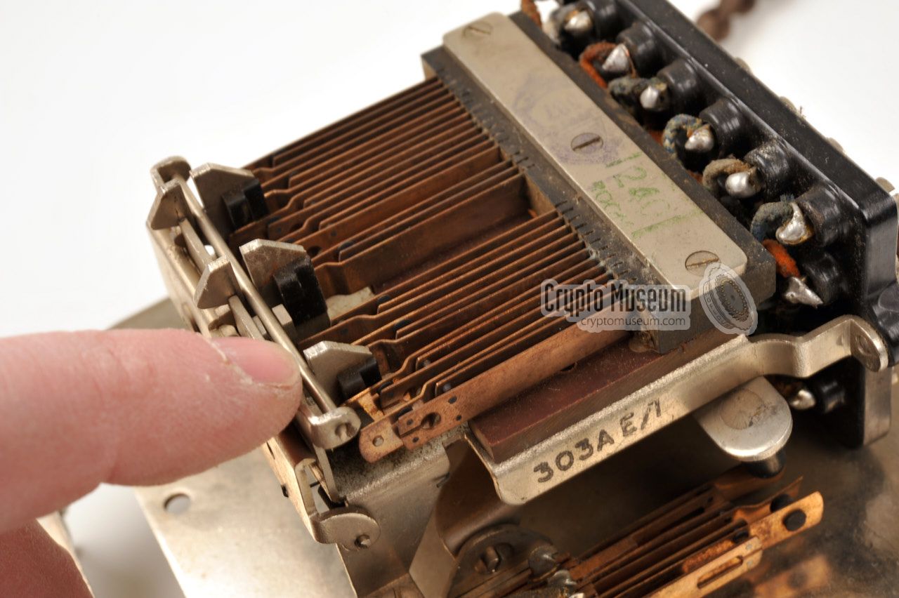
As multiple contacts are needed for switching microphone
and speaker,
Key No. 303/A
is used. It consists of three individual switches
with 4, 1 and 4 sets of make-before-break contacts each.
This arrangment is also known
as 4K-1K-4K 1 , and the complete set is often referred to as 9K.
Towards the front of the key assembly are three plungers that are operated
by the buttons on top of the phone. The
behaviour of the plungers is
controlled by a spring-loaded latch bracket
that is fitted at the front.
In the current setup,
both buttons are latched when they are depressed.
|
|
|
Pressing the third button at the centre – when installed – releases
the other two. Depending on the function of the centre button — it
can be used for example to redial a number, to call the operator,
or connect to an extension — it may be configured to latch or to
release itself.
|
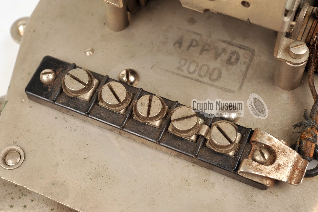
At the rear side of the No. 303A switch pack
is a 28-point contact block
with screw terminals, to which the actual contacts of the 9K (4K-1K-4K)
switches are wired. This allows the switch pack to be used for
virtually any configuration or application,
simply by wiring it up as required.
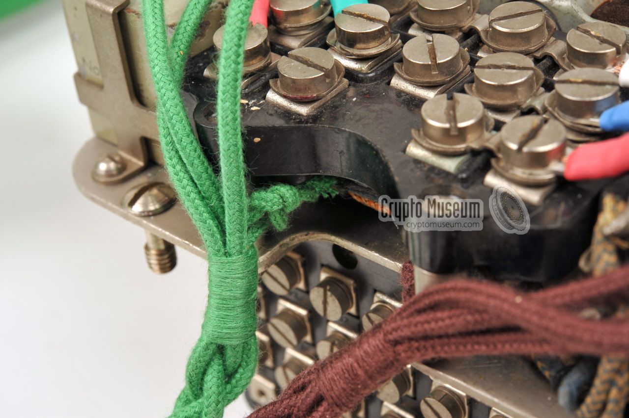
The line cord and the braided handset cord, are usually fixated to one
of the mounting posts of the terminal block, by means of tie knot.
Note that the bell
was optional on the 394 and 396 phones. It was only
fitted when required by the customer. It is present in the phone shown here.
|
|
|
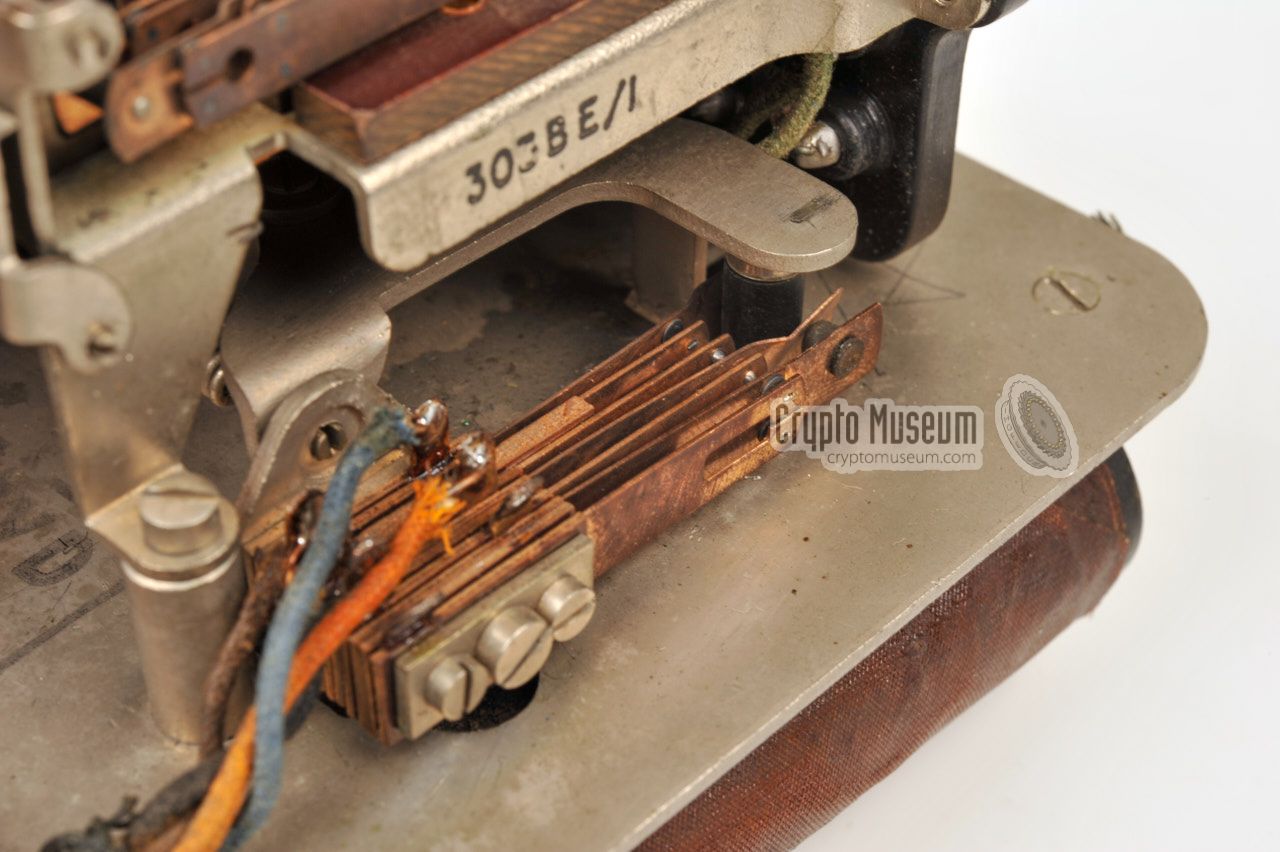
Note that in the images above, the device is fitted with a brown 4-wire
cable connection to the subscriber line. This is incorrect, as the device needs
6 to 8 wires for operation with a Frequency Changer (scrambler).
In 2021, the device was fitted with a correct cable and rewired for
operation with Frequency Changer 6AC and with
Privacy Set 8.
➤ Technical details about 300-series phones
|
-
In Ericsson terminology, a single make-before-break set of contacts
is known as a 1K springset. Likewise, a double set is known as 2K and a
set of four make-before-break contacts is called 4K.
More...
|
|
The SA 5063/0 and 5063/1 voice terminals shown in the image
above are authentic and were used during WWII with a
Frequency Changer.
According to the stamps,
one was made in 1938, whilst the other one is of 1940 vintage.
The green handset was made in 1935. The painted one in 1940.
According to the markings at the bottom,
they were issued in 1943 and 1944 respectively.
|
The problem with these two sets however, was that a previous owner had
converted them into house telephones, or intercoms, and used them this way
for several years. Obviously he wanted to avoid the use of a small exchange,
or PABX, and had converted them for low power use.
The original bell had been removed and its space was used to
accomodate two 4.5V batteries:
one for the speech loop and one for a small buzzer
that was mounted to the chassis. Luckily, the previous owner had applied
his modifications in such a way that they could easily be reversed.
|
|
|
|
A bakelite button had been added to the center
of the circular panel that covers the hole of the dial,
but this too was easily removed.
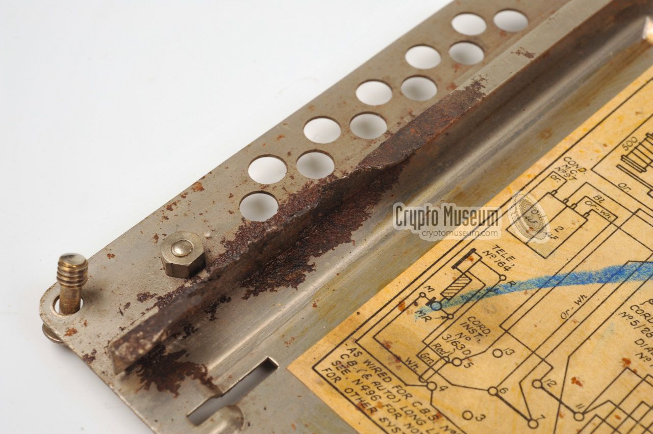
The bad news was that the batteries were left inside the phones when they
were taken out of service. Over the years, the leakage from the batteries
had caused considerable damage
to the bottom panel and to the small drawer at the phone's front.
|
Restoration of the phones was started by first taking them fully apart
and cleaning the indiviual parts. The modifications were removed and undone
and the bakelite body
of the unit was washed and treated with bakelite conditioner. 1
The missing parts were then re-mounted to the chassis and the
original wiring was restored as per circuit diagram inside the bottom panel.
The braided cord of the green bakelite handset was replaced with a
high-quality reproduction 2 and a new braided line cord was added to allow
it to to be connected to a standard telephone line.
|
|
|
|
The two telephone sets phones are now fully restored to their original
state as close as possible (2016). After acquiring two original
Frequency Changer No. 6AC/3 units in 2021,
the telephone sets were internally rewired, to match the
wartime configuration. Furthermore, they were fitted with an 8-wire
braided cord, so that they could be connected directly to a
Frequency Changer.
|
-
High-grade bakelite conditioner and other products for restoring
bakelite parts are available from a variety of sources,
such as this one.
-
High-quality reproduction cables for old GPO phones, that closely
match the original colours and manufacturing properties, are
available from Chris Elliot in the UK.
|
K13 BR3 K16 BT1 Line (B) K17 T9 K18 BT7 K19 M Handset, microphone (red) K20 T4 K21 BT6 K22 BT4, BT5 K23 T5 K24 MR Handset, common (white) K25 BT8 K26 T6 K27 R Handset, receiver (speaker) (green) T1 BT2 Line (A)
|
The drawing below shows the pin numbering of the standard connection
block or terminal (T) of the basic telephone set, as seen from
the bottom .
In the circuit diagram
above and the internal wiring table above, these
contacts are prefixed with the letter 'T' (e.g. 'T9').
➤ Further information
|
| |
Connection block T as seen from the bottom of the phone
|
|
Below is the layout of the contact terminals of connection block 9K,
also known as Key Unit 303, as seen from the rear of the telephone set.
In the circuit diagram and the
internal wiring table above, the contact numbers of the Key Unit
are prefixed with the letter 'K' (e.g. 'K23').
➤ More
|
| |
The switches inside the 9K switch pack with their terminal numbers
|
|
|
In some cases, the SA-5030 was externally wired via Block Terminal BT-20/8.
Note that all 8 contacts are used. The Block terminal accomodates the
subscriber line as well as the wiring to and from the Scrambler.
The exact wiring diagram is shown in the circuit diagram above.
|
- Line (B)
- Line (A)
- Ground (earth)
- Speaker (L) 1
- Microphone (L) 1
- Microphone (H)
- Switched Line (A) - to Frequency Changer 2
- Speaker (H)
|
|
-
Contacts 4 and 5 are shorted. They are connected to the common line
of the handset (via KA3).
-
This line is controlled by switch KA1. It connects the Frequency Changer to
the subscriber line when in secure mode.
|
To allow the Frequency Changer and suitable telephone sets to be tested, used
and demonstrated in various configurations, without altering the fragile
vintage wiring of the devices all the time, Crypto Museum has defined its own
standard, involving inline 7-pin male/female
XLR connectors.
In this standard, an 8-point junction box BT 20/8 is used as the
central hub. The SA 50xx voice terminal is fitted to the BT 20/8 via
a fixed 8-wire braided cable. The subscriber line is also fitted to the
BT 20/8 via a fixed 2-wire or 4-wire braided cable, whilst a fixed
7-wire braided cable with an XLR7/F connector
at the end is present for quick (dis)connection of the Frequency Changer.
The Frequency Changer itself is fitted with a fixed 7 or 8-wire braided cable
with an XLR7/M connector at the end. This allows the Frequency Changer
to be disconnected from the setup without opening it and unscrewing the
wires from its terminal block or from the
BT 20/8.
Below is the pinout of the XLR7/F on the cable that is fitted to the
BT-20/8 terminal block.
|
- Line (B)
- Line (A)
- LB (or unused)
- Microphone (H)
- Microphone (L)
- Speaker (L)
- Speaker (H)
|
|
-
P.O.E.D. = Post Office Engineering Department.
|
|
|
|
Any links shown in red are currently unavailable.
If you like the information on this website, why not make a donation?
© Crypto Museum. Created: Wednesday 26 May 2021. Last changed: Monday, 05 July 2021 - 09:01 CET.
|
|

|
|
|


