|
|
|
|
|

|
|
UK Phone Voice Scrambler SA 5031 → ← No. 162
|
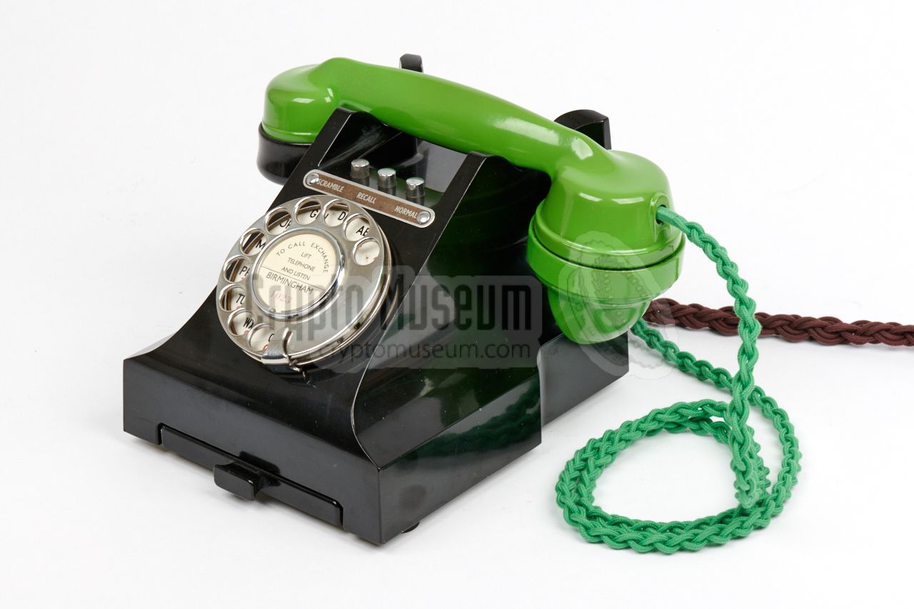
Telephone set used with scrambler phone · 1940
|
The set has two push-buttons labelled SECRET and
NORMAL (later: SCRAMBLE & NORMAL), just above the dial.
Only the SCRAMBLE button is latched. It is released when
the other button is pressed on when the handset is placed on hook.
An extra button could be fitted at the centre,
to provide RECALL on PABX
installations that supported this feature, or for use with various extension plans.
In such cases the label would be changed accordingly, for example:
SCRAMBLE - RECALL - NORMAL, and in most cases a dial would be fitted
to allow direct (auto) calls.
|
|
|
|
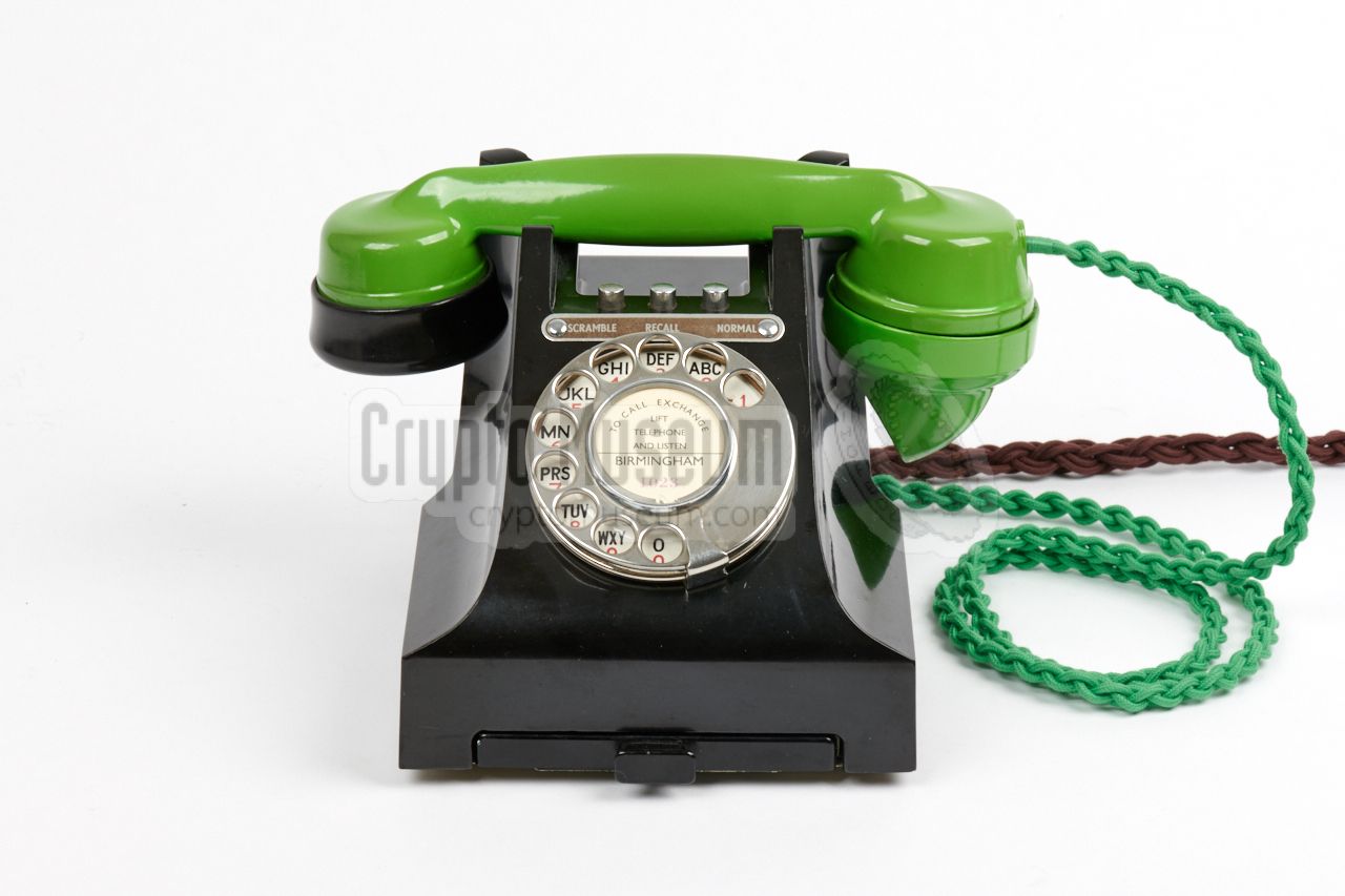
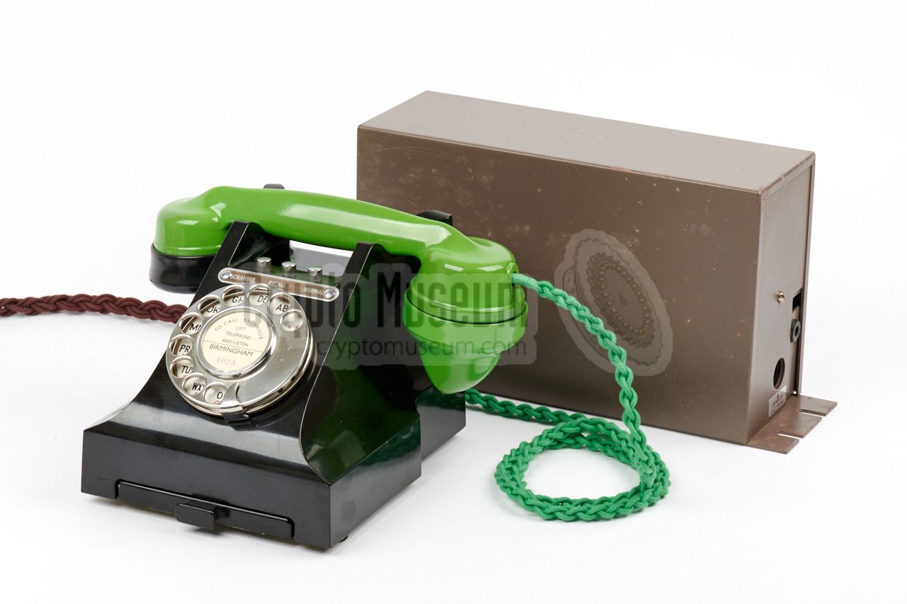
Factory assembled SA5030 units (marked SA5030 at their base) are extremely rare,
as most of them were built by engineers in the field from locally available parts.
Such items are generally marked Tele. No. 328 on their base and chassis.
The image above shows such a Tele. No. 328 that was converted into an SA-5030
by a technician in the field. Due to shortages at the time of manufacturing
(World War II), a lime-green-painted black bakelite
handset is used. The green handset cord is a high-quality reproduction that was
fitted when the unit was restored. 2
|
-
7 or 8 wires if a PABX Recall button is fitted.
-
Restoration by Andy Grant [1].
Green reproduction cord obtained from Chris Elliot.
|
Below is the internal wiring diagram of the
SA 5030 telephone set.
At the bottom right are the (A) and (B) terminals of the subscriber line.
Directly above it, is the wiring to the screw terminals of the
Frequency Changer 6x.
The make-before-break (MBB) switches KA and KB are part of
the 303/A Key Unit
that is controlled with the 2 (or 3) push-buttons on top of the
telephone set.
They allow the telephone set to be used for plain as well as secure
calls. In secure mode, the speaker and microphone of the telephone's
No. 164 handset are routed via the Frequency Changer 6x.
During WWII, the dial armature was often omitted from the
SA-5030 telephone sets,
as the British Government used a private telephone network
– completely separated from the public switched network –
that was patched manually. The diagram above is also applicable to
the SA-5063 and other
300-series telephones
that were modified for use with the Frequency Changer.
|
K13 BR3 K16 BT1 Line (B) K17 T9 K18 BT7 K19 M Handset, microphone (red) K20 T4 K21 BT6 K22 BT4, BT5 K23 T5 K24 MR Handset, common (white) K25 BT8 K26 T6 K27 R Handset, receiver (speaker) (green) T1 BT2 Line (A)
|
The drawing below shows the pin numbering of the standard connection
block or terminal (T) of the basic telephone set, as seen from
the bottom. In the circuit diagram above and in the
internal wiring table above, these
contacts are prefixed with the letter 'T' (e.g. 'T9').
➤ Further information
|
| |
Terminal block (T) as seen from the bottom of the phone
|
|
Below is the layout of the contact terminals of connection block 9K,
also known as Key Unit 303,
as seen from the rear of the telephone set.
In the circuit diagram and the
internal wiring table above, the contact numbers of the Key Unit
are prefixed with the letter 'K' (e.g. 'K23').
➤ More
|
| |
Terminal block of the Key Unit (K) as seen from the rear of the phone
|
|
|
In most cases, the SA-5030 was externally wired via Block Terminal BT-20/8.
Note that all 8 contacts are used. The Block terminal accomodates the
subscriber line as well as the wiring to and from the Scrambler.
The exact wiring diagram is shown in the circuit diagram above.
|
- Line (B)
- Line (A)
- Ground (earth)
- Speaker (L) 1
- Microphone (L) 1
- Microphone (H)
- Switched Line (A) - to Frequency Changer 2
- Speaker (H)
|
|
-
Contacts 4 and 5 are shorted. They are connected to the common line
of the handset (via KA3).
-
This line is controlled by switch KA1. It connects the Frequency Changer to
the subscriber line when in secure mode.
|
To allow the Frequency Changer and suitable telephone sets to be tested, used
and demonstrated in various configurations, without altering the fragile
vintage wiring of the devices all the time, Crypto Museum has defined its own
standard, involving inline 7-pin male/female
XLR connectors.
In this standard, an 8-point junction box BT-20/8 is used as the
central hub. The SA 5030 voice terminal is fitted to the BT-20/8 via
a fixed 8-wire braided cable. The subscriber line is also fitted to the
BT-20/8 via a fixed 2- or 4-wire braided cable, whilst a fixed
7-wire braided cable with an XLR7/F connector at the end is present for
quick (dis)connection of the Frequency Changer.
The Frequency Changer itself is fitted with a fixed 7- or 8-wire braided cable
with an XLR7/M connector at the end. This allows the Frequency Changer
to be disconnected from the setup without opening it and unscrewing the
wires from its terminal block or from the
BT-20/8.
Below is the pinout of the XLR7/F on the cable that is fitted to the
BT-20/8 terminal block.
|
- Line (B)
- Line (A)
- LB (or unused)
- Microphone (H)
- Microphone (L)
- Speaker (L)
- Speaker (H)
|
|
|
|
|
Any links shown in red are currently unavailable.
If you like the information on this website, why not make a donation?
© Crypto Museum. Created: Wednesday 26 May 2021. Last changed: Monday, 05 July 2021 - 09:00 CET.
|
 |

|
|
|


