|
|
|
|
|

|
|
UK Phone Voice Scrambler Overview → ← No. 7
The device is fully compatible 2 with all earlier models
and was initially used in combination with the old
SA5030 voice terminal. The
terminal was later succeeded by
Telephone No. 710 and 740,
which had a more modern look and feel.
As the device was manufactured by several UK suppliers,
there are variations in the physical construction and in the electronic
circuits, but the outer dimensions are always the same.
It was in production from 1962 to at least 1972, whilst
refurbished versions of Privacy Set No. 8, 8A, 9 and 9A have been spotted
as late as 1977 [1].
|
|
|
Some manufacturers, such as TMC, incremented the model number each time
the circuit diagram was updated, which is how the model numbers 8, 8A, 9
and 9A came into existence. They are all iterations of the same basic design
however. Other manufacturers, such as EMI, kept the name Privacy Set No. 8
throughout the lifetime of the product, despite significant changes.
Generally speaking, changes can only be tracked by looking
at the production code, for example:
TES 64/1 means TMC 1964 production batch 1, whilst
EMT 72/1 means EMI 1972 production batch 1.
Below is an overview of the different versions and production codes
of Privacy Set 8, 8A, 9 and 9A that we have encountered over the years.
As there are significant differences between versions and manufactuers,
each variant is listed on a separate page, complete with a detailed technical
description, a block diagram, detailed circuit diagrams and a
description of its interior.
|
 |
-
Privacy Set No. 8 first appears in GPO diagrams in 1962.
it is intended for use on CB/Auto systems only.
-
Only when the same carrier frequency is used.
|
|
In addition to the model and versions, there were also production variants
for various types of applications, commonly identified in GPO terminology with a
group number that was added to the model number (e.g. '/3'). The exact
meaning of these group identifications is currently unknown.
So far, the following production variants have been observed:
|
- Carrier frequency
By default, all Privacy Sets use a carrier frequency of 2500 Hz, so that
they are backwards compatible with all earlier models. In some cases, for
example when additional security was required, different carrier frequencies
were used, such as 3000 Hz and 2000 Hz.
This requires a different oscillator,
but also different low-pass filters in the transmission and reception path.
The Privacy Set No. 9A in our collection uses a 2000 Hz carrier.
- Power supply
Most Privacy Sets were supplied with an internal mains power supply unit
(PSU), but it was also possible to power it from an external 12V DC
supply, such as the battery of a car. In the latter case, the PSU was
omitted and the 15 mA current for the carbon
microphone (when present) has to be extracted from the subscriber line.
- 2-wire and 4-wire operation
Both sides of the device can be configured for 2-wire or 4-wire operation.
In most cases, the unit was strapped for a 2-wire subscriber line, and a
4-wire (bare) handset. This is knows as 2-wire to 4-wire operation.
When connecting the device to a 4-wire leased line or to a radio, it could
be configured for 4-wire operation. This is known as
4-wire to 4-wire operation. With some versions of the device
it was also possible to connect a regular telephone set instead of the
handset — i.e. behind the scrambler —
in which case 2-wire to 2-wire operation was possible. The latter
was not recommended however.
|
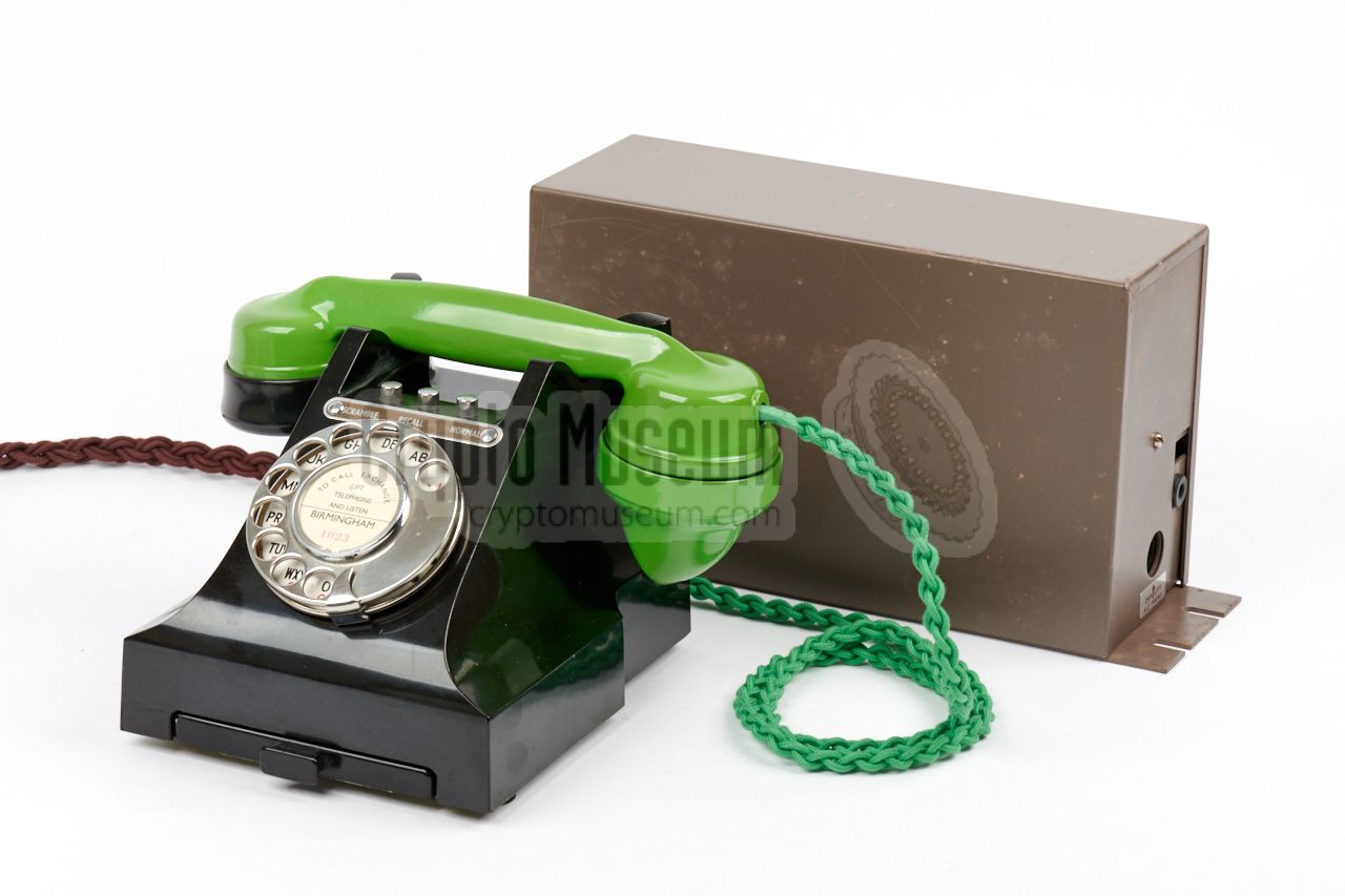
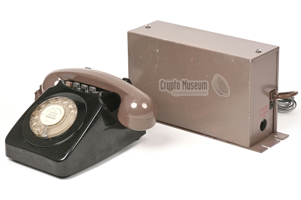
The diagram below shows how the scrambler
works. At the right is
the 2 or 4-wire line to the exchange or to a radio. At the left
is the voice terminal, which can be an individual microphone and
speaker, a handset or a telephone. The audio signal from the
microphone is first attenuated to reduce its dynamic range.
It then passes a low-pass filter, so that
only the 20-2000 Hz part of the spectrum is fed to a ring mixer,
where it is added to the 2500 Hz signal from an oscillator.
At the output of the mixer, the sum
and the difference
of the two signals are available, with the difference being the
mirrored version of the original signal (here shown in red).
This means that low-frequency tones have become high-frequency
tones and vice versa.
After filtering it again in a low-pass filter, only the mirrored
signal is left, which is then amplified and delivered to the line.
The bottom half of the diagram shows the reception path, which is
more or less the same, but in reverse direction. The mixer
produces two images again, of which the lower one is the mirrored
version of the received signal. After filtering, the original
audio signal remains, which is then amplified and delivered
to the speaker. The spectrum diagrams should illustrate what happens.
Although the Frequency Changer, or frequency inverter, offered
reasonable protection against an occasional (un)intentional eavesdropper,
such as the exchange operator or a service engineer working on the
lines, it was no match for a professional interceptor. All one had to
do, was find the inversion frequency and mirror the spectrum again.
A classical case of security by obscurity.
➤ More about scramblers
|
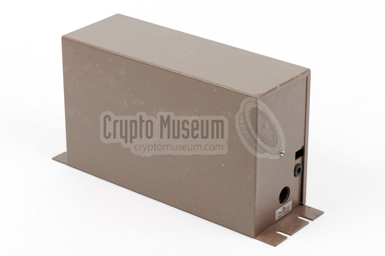
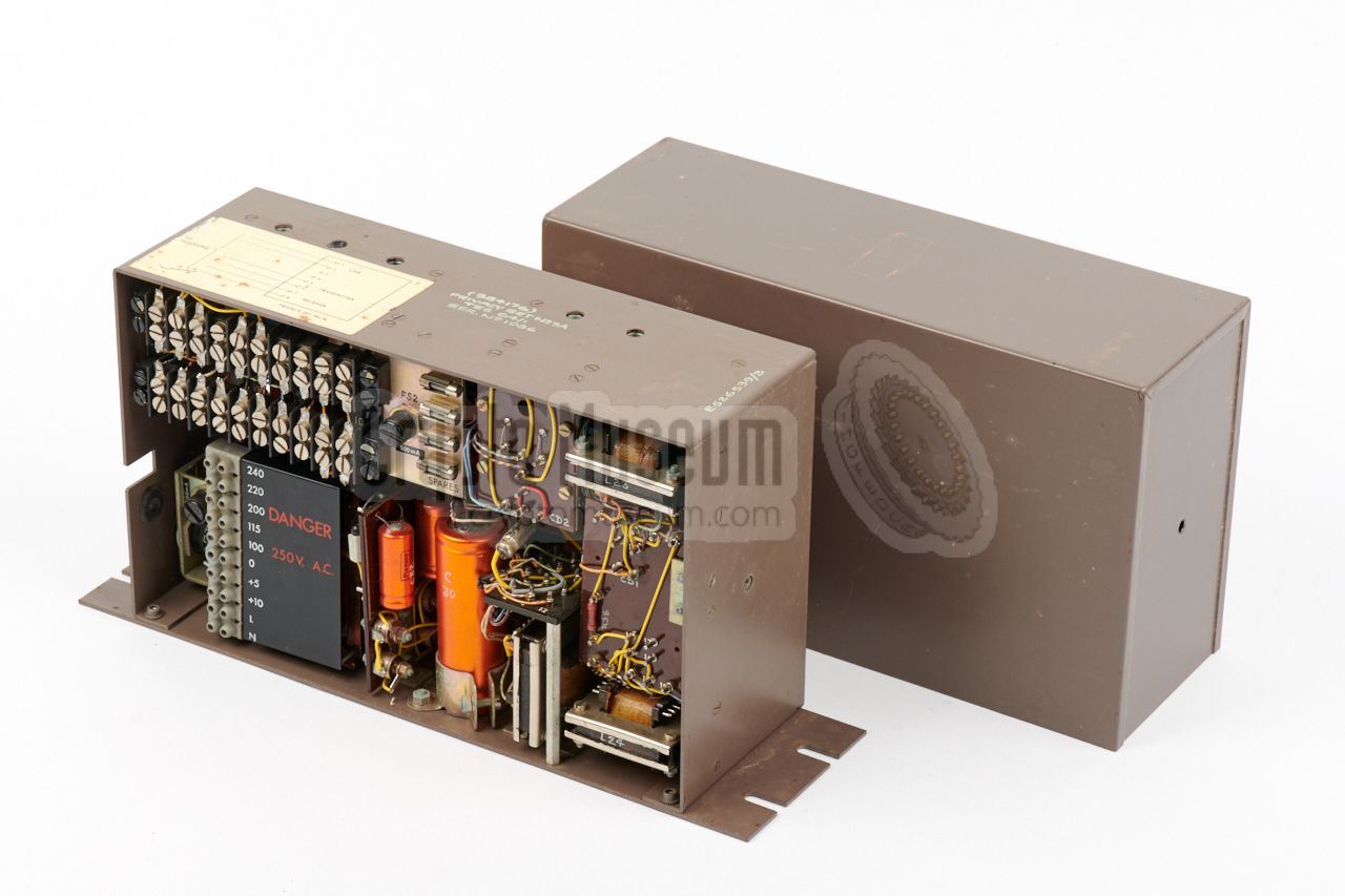
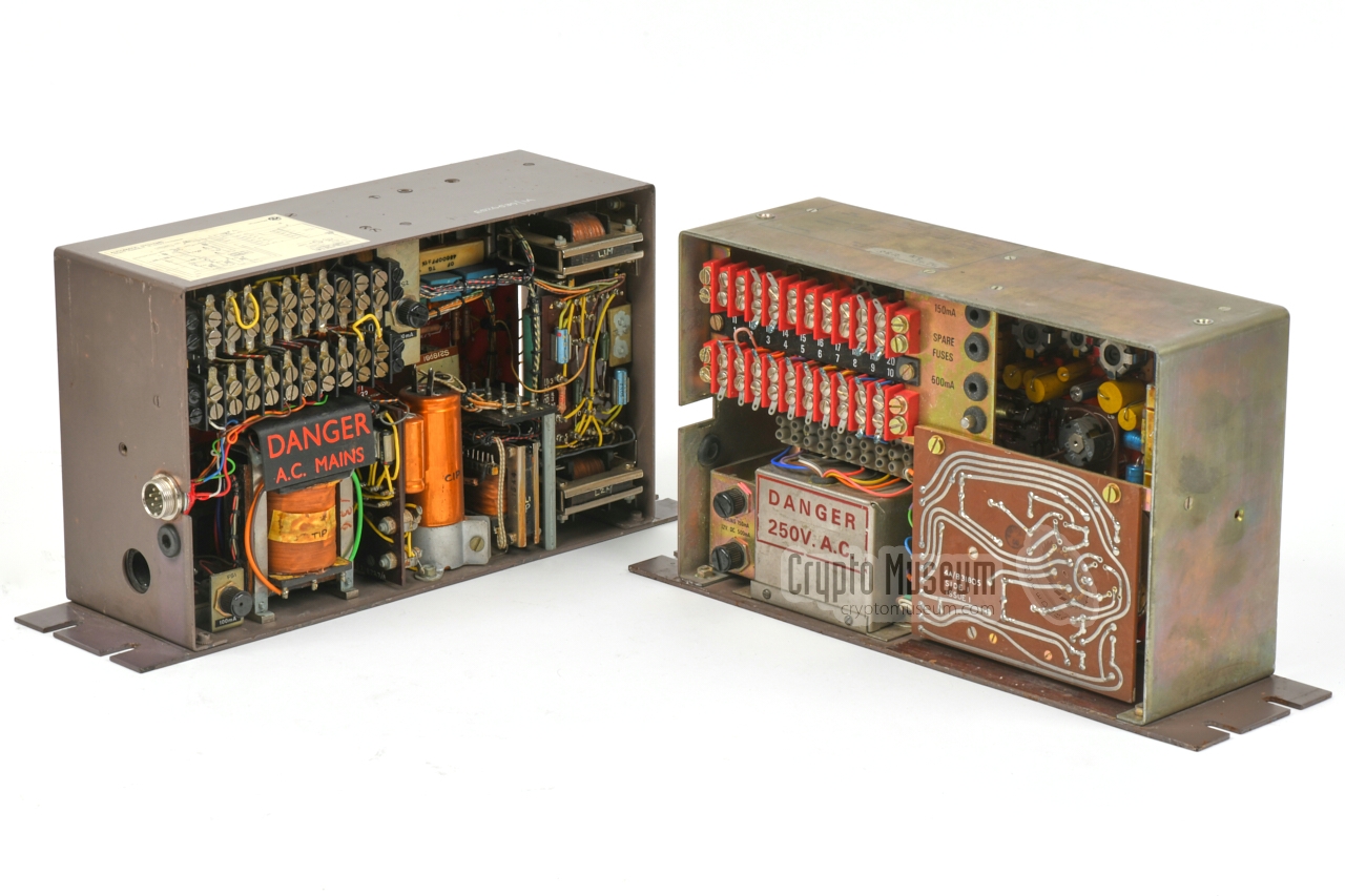
All No. 8, 8A, 9 and 9A versions of the Privacy Set had the same external
dimensions, regardless the manufacturer.
The mounting holes, the power inlet
and the line cable cutout are at the same position, so that the devices are
interchangeable. The interior however, varies strongly between
manufacturers,
as shown in the image above. The one on the left was made in the 1960s by
TMC and carries the manufacturing code TES 64/1. The one the right is
from the 1970s and carries the manufacturing code EMT 72/1. Although this
is not certain, it was probably made by EMI. 1
All the devices have in common, are the outer dimensions,
the layout of the terminator block at the top left and the
electrical specifications, to ensure that they are interoperable.
Check out the individual page for each version and variant for
additional information, block diagrams, circuit diagrams and a description
of the interior.
|
|
-
The manufacturer code EMT is still unconfirmed, but belongs with
99% certainty to EMI. On these pages, we will refer to devices with
the EMT manufacturer code as 'EMI-version'.
|
|
|
Privacy Set No. 8
TE 62/1
|
|
|
|
|
Privacy Set No. 9A
TES 64/1
|
|
|
Also made by TMC, this version was introduced in 1964. It is nearly
identical to the 1962 Privacy Set No. 8 (shown above), but has several small
improvements. In addition, the ability to connect a standard telephone set
behind the scrambler was dropped on this model.
➤ More information
|
|
|
|
|
Privacy Set No. 8
EMT 72/1
|
|
|
This version of Privacy Set No. 8 was made by EMI in the early 1970s
and is built with 1N1303 and 1N1309 PNP Germanium transistors.
It is more service-friendly, as the PCBs are hinged and no external parts are
used. Furthermore, the electronic circuits are improved in various ways.
➤ More information
|
|
|
Type Voice scrambler Principle Single frequency inversion Manufacturer see below Users see below Carrier 2500 Hz or 3000 Hz or 2000 Hz Impedance Standard telephone line at 150, 300 or 600Ω Terminal Modified conventional analogue telephone set Power Internal (mains) or external (12V DC) Mains 100/115/200/220/240V AC, + 0/5/10V AC Dimensions 255 × 155 × 90 mm (305 × 155 × 90 mm with mounting flanges) Weight 4000 grams (EMI) - 4500 grams (TMC)
|
|
Privacy Set No. 8 was used by the British Government in the 1960s, 70s
and 80s, and also by a number of selected (approved) customers, such as
foreign embassies and large corporations and organisations. Below is a
non-exhausive list of known users:
|
|
Apart from The General Post Office (GPO) there were several commercial
parties that were allowed to produce the Privacy Set No. 8 and 9.
|
FH General Post Office (GPO), Holloway TE Telephone Manufacturing Company (TMC), Dulwich, London (UK) TES Telephone Manufacturing Company (TMC/Pye), St. Mary Cray, Kent (UK) GCL EMI Communications RAA Landis & Gyr, formerly: Aeronautical & General (AGI) EMT EMI Telephone Manufacturing 1 ? Standard Telephones & Cables (STC) ? Plessey
|
-
The manufacturer code EMT is still unconfirmed, but it most likely
belongs to EMI.
|
No. 8 1033 Crypto Museum No. 9A 1086 Crypto Museum No. 8 3086 EMT 71/1 Museum of Technology (UK) No. 8 3476 Crypto Museum No. 8 - Crypto Museum
|
|
|
|
Any links shown in red are currently unavailable.
If you like the information on this website, why not make a donation?
© Crypto Museum. Created: Wednesday 26 May 2021. Last changed: Tuesday, 10 August 2021 - 16:37 CET.
|
|

|
|
|


![Block diagram of the Frequency Changer. Click to see the original drawing [1].](files/ps_block.jpg)

