|
|
|
|
|

|
|
UK Phone Voice Scrambler No. 8 Overview → ← No. 7
|
|
Privacy Set No. 8
TE 62/1
|
|
|
It is fully compatible with
earlier models
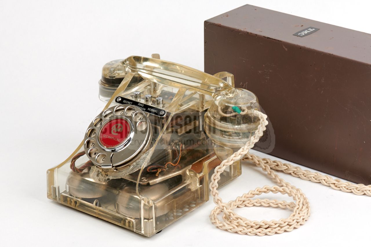
and was initially used in combination with the
SA5030 voice terminal, that was based on a
GPO 300-series telephone set.
The latter was eventually succeeded by a modified
Tele. No. 710 or 740.
Privacy Set No. 8 was in production from 1962 to 1972 and was made
by several manufacturers. Refubished No. 8 units have
been spotted as late as 1977 [1].
The outer dimensions of the device and the position of
the cable inlets are identical for all versions regardless the
manufacturer, but there are significant differences in the interior.
|
|
|
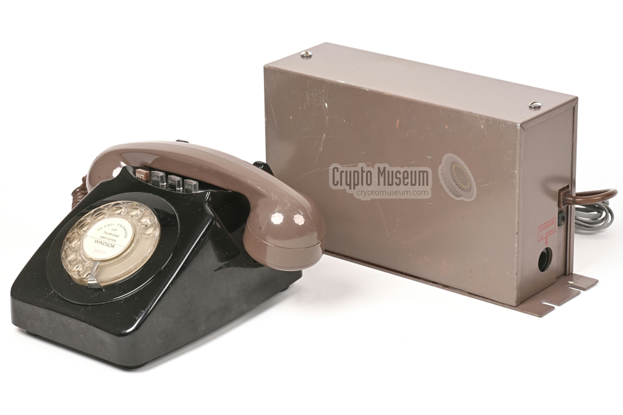
This page describes specifically the version of Privacy Set No. 8
that was made in 1962 by the
Telephone Manufacturing Company (TMC),
as indicated by the marking TE 62/1 at the bottom of the unit.
The circuit is comparable to that of its predecessors, such as the
valve-based Frequency Changer 6AC, except that it is made
with the first generation of OC71 Germanium transistors.
A unique feature of the TMC-version of this device is the presence of
a secondary fork circuit, which allows an ordinary telephone set to be
connected behind the unit, instead of a modified telephone set (voice terminal)
or a bare handset. This is also known as 2-wire/2-wire operation.
In addition it has a bypass circuit, which passes the
signalling from the subscriber line directly to the connected telephone
set and vice versa, without leaking plain voice to the line.
The secondary fork and the bypass circuit are omitted from the
Privacy Sets of some other manufacturers.
➤ Versions made by other manufacturers
|
Privacy Set No. 8 was originally developed by the GPO,
but was made by various manufactuers.
Although the circuit is largely the same
for all versions, there are notable differences between them.
Sub-circuits may be added, changed, or left out altogether. The specific
differences are discussed below.
For a more general discussion of the Privacy Set's block diagram,
look here.
At the right is a fork circuit that connects the subscriber line
to the voice circuits of the Privacy Set. At the left is the handset
with its microphone and speaker. A special feature of
this version is the presence of an additional fork circuit,
which is combined with the output transformer of the reception path.
This 2nd fork can be used to connect a regular 2-wire
telephone set directly to the Privacy Set, instead of the bare handset.
This is known as 2-wire to 2-wire operation.
The block diagram above shows how this is done. At the right is the
subscriber line, which is connected to the primary fork circuit. At the left
is a regular telephone set which is connected to the secondary fork circuit.
The bypass circuit ensures that the bell signal is delivered directly
to the telephone set and that the dial pulses from the telephone set
are passed directly to the line, whilst speech is processed exclusively by the
voice circuits of the Privacy Set.
For this to work properly, it is necessary to simulate a regular
subscriber line for the telephone set, which is why this version of the
Privacy Set has two power supplies: 12V DC for the inverter circuits and
60V DC for the simulated line. The 60V DC power supply, which is actually
a current source, also provides the current for operation of the
carbon microphone of the handset.
It is doubtful though whether this 2-wire/2-wire configuration was used
in practice, as it would be difficult to sufficiently suppress feedback
(sidetone) of the scrambled audio in the handset.
The possibility for 2-wire/2-wire operation was dropped in later versions
of the device.
➤ General description of Privacy Set No. 8
➤ About frequency inversion
|
|
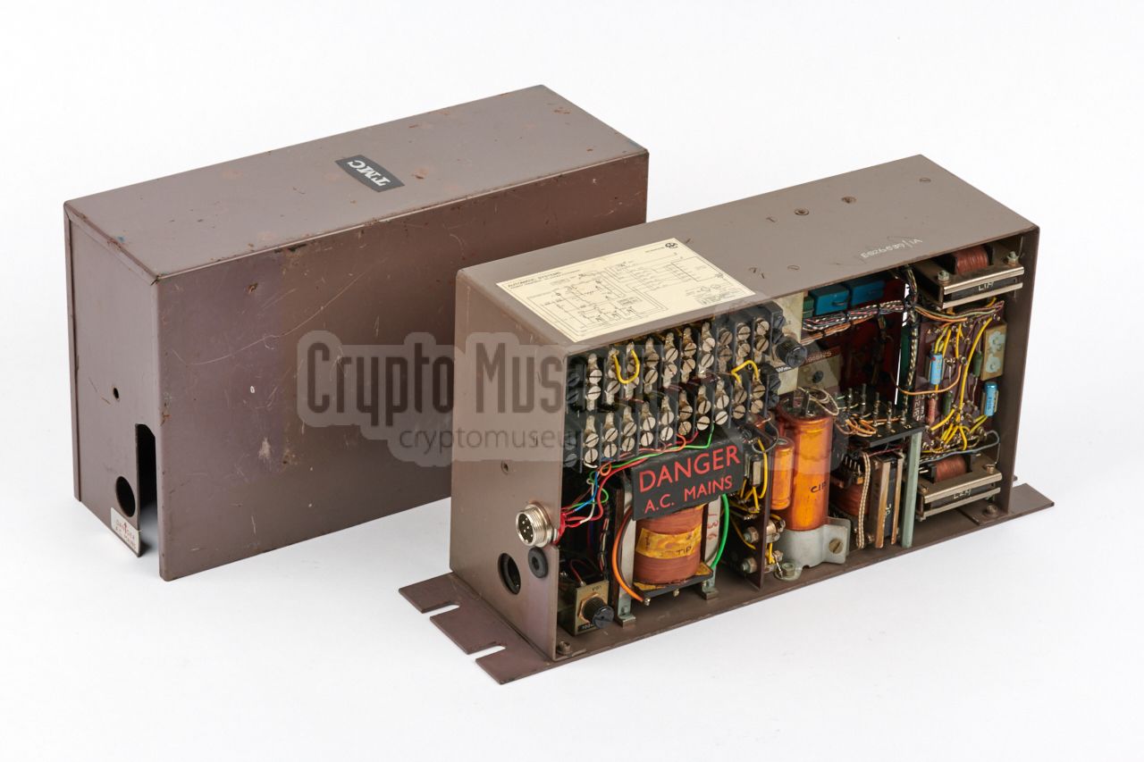
The TMC version of Privacy Set No. 8 is housed in a
brown metal enclosure
that measures 255 x 155 x 90 mm and weighs 4520 grams. The device has no
controls. The interior can be accessed by removing the two bolts at the
centre of the short sides, after which the
cover can be lifted off.
Glued to the top of the frame is a
connection diagram
for configuration of a suitable telephone set that acts as the voice
terminal. This diagram is discussed in detail
further down this page.
|
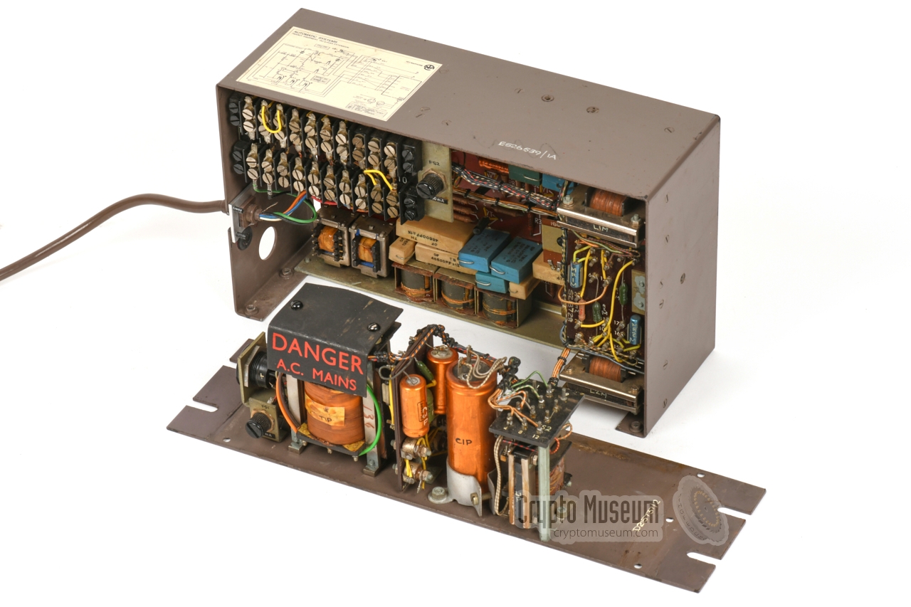
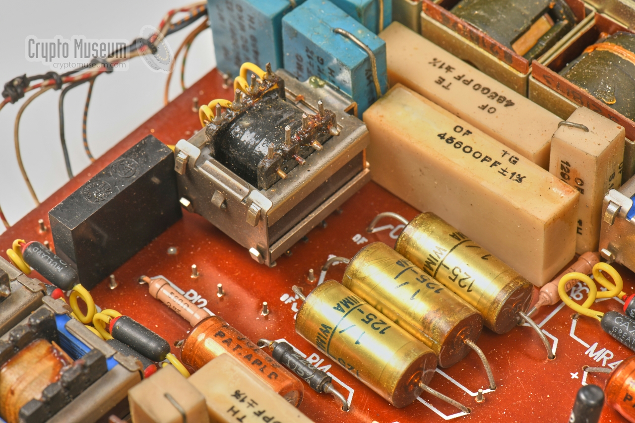
Inside the device is a
standard terminator block mounted in the upper
left corner, a mains transformer bolted to the
bottom and several supporting circuits mounted
to the right side. Hidden behind all this is the
actual inverting board which occupies the entire
rear section.
The power supply unit can be separated from the device by removing
six recessed screws from the bottom of the case, after which the
bottom part can be extracted, as shown in the image above.
It holds the mains transformer, diode rectifiers, smoothing capacitors
and a large choke coil.
|
|
|
|
On top of the transformer, protected by a removable black piece
of carton, are the solder straps for
selection of the desired mains voltage.
By default, it was configured for 240V AC, the (then) mains
voltage in the UK. This configuration is now also suitable for mainland
Europe (230-240V).
|
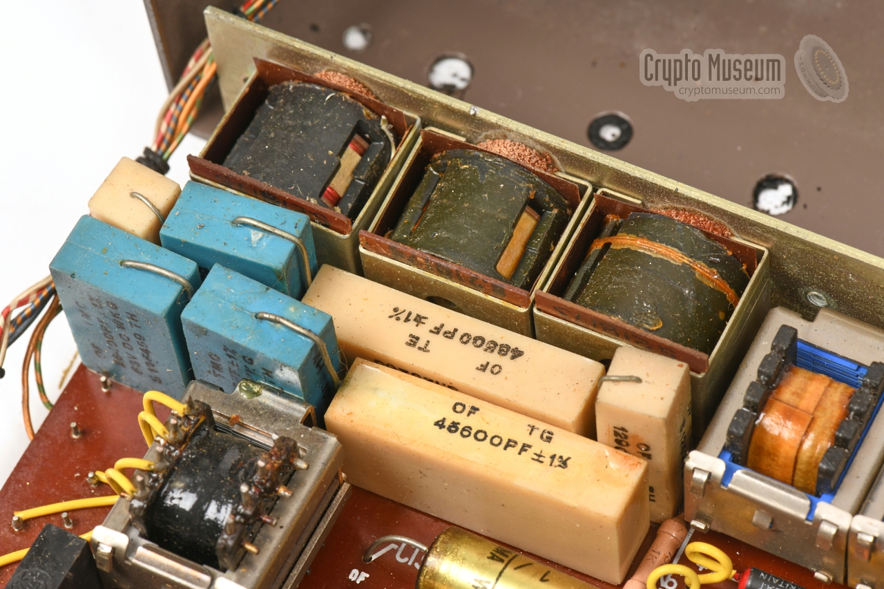
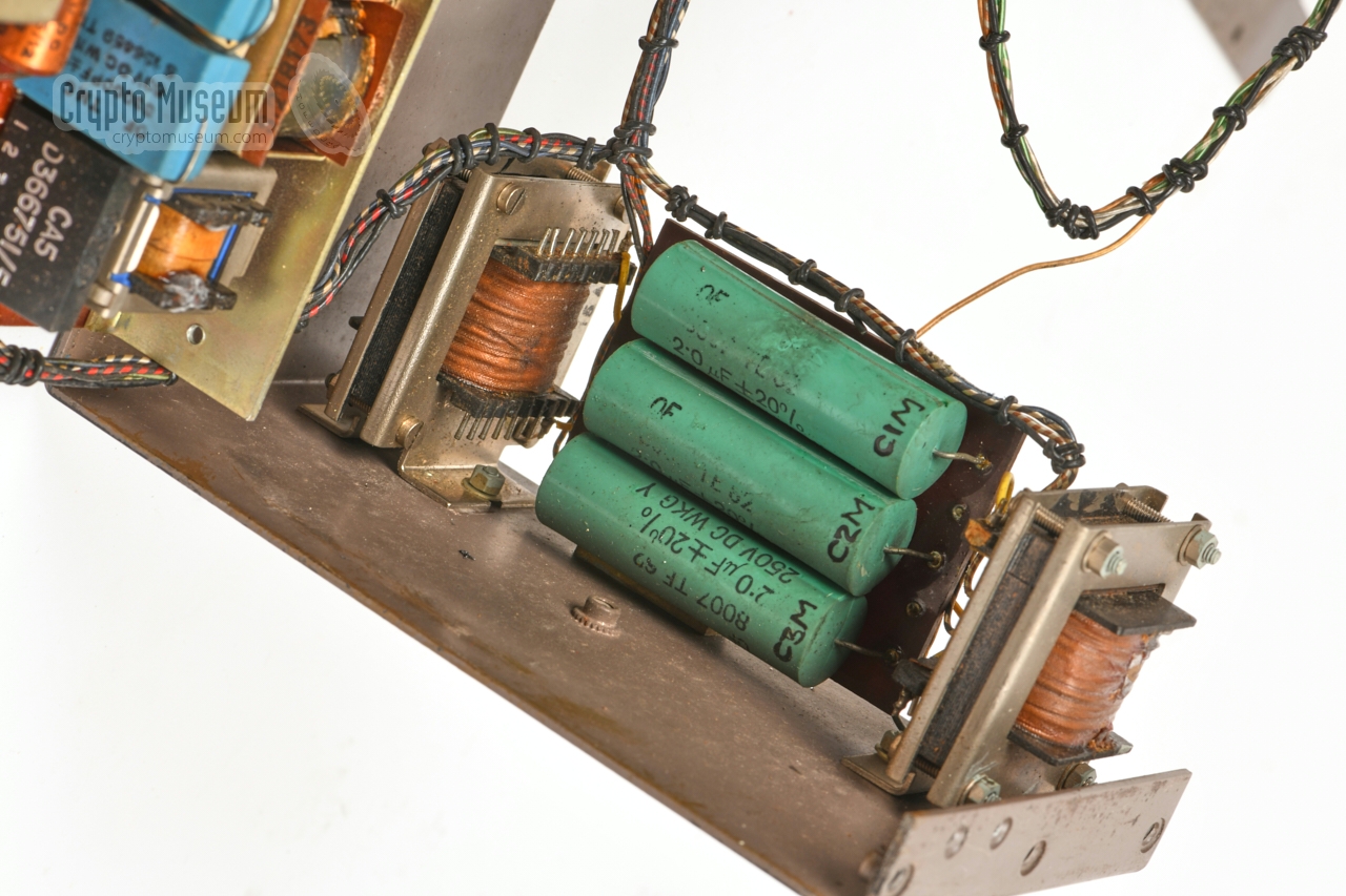
The transformer has two secondary windings of 15V (for the inverter board)
and 50V (for the microphone and secondary line current source) respectively. Rectifying
diodes and smoothing capacitors are also present on the bottom panel,
along with a choke coil for the -12V power rail.
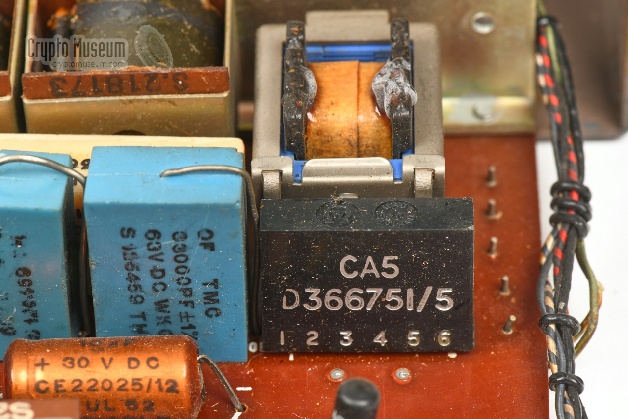
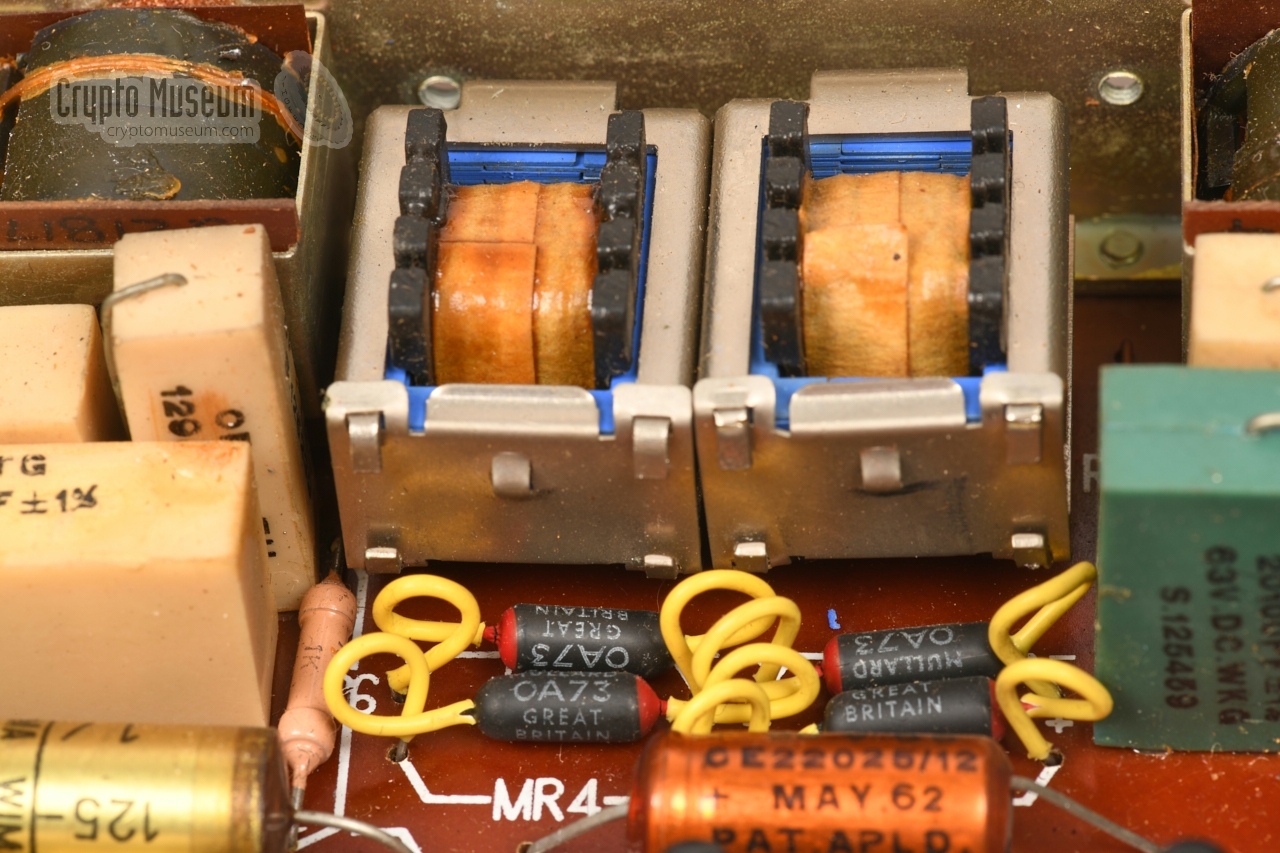
At the right, mounted to the side panel of the chassis, are two choke coils
plus a small interface board that contains supporting components for injecting
a 15 mA current into the handset's carbon microphone. It is also used for the
rarely used (optional) 2-wire/2-wire configuration.
|
|
|
|
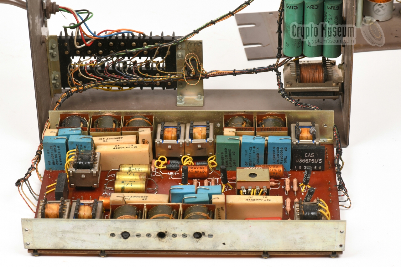
The board also contains two diodes and a number of resistors, that were
omitted in later versions of the unit, probably because the 2-wire/2-wire
option was no longer supported. At the bottom of this board are
three large green 2µF/250V capacitors that are used for a variety of options.
|
The actual inverter board (the speech scrambler) is mounted behind
the visible parts, in the rear section of the chassis. Getting access to
its parts is cumbersome and requires the board
to be removed from the chassis. This is achived by removing 4 recessed
screws from the bottom edges of the chassis and another 4 at the top.
Note that one or more screws at the top may be
obscured by the connection diagram.
Once the screws have been removed, the inverter board can be freed
from the chassis by pushing it towards the rear and folding it down
as shown.
|
|
|
The various sub circuits are identified in the diagram below.
At the top is the transmission path (TX), starting with the input transformer
at the right. The path consists of an 11dB attenuator, a low-pass filter, a
modulator, another low-pass filter and finally a 2-stage amplifier. The output
of the amplifier is supplied to the fork – also known as
the hybrid transformer – at the left centre.
At the bottom is the reception path (RX). Starting at the fork, the signal
passes a 6dB attenuator and is then applied to the demodulator. The output of
the demodulator is taken through a 3-stage low-pass filter into a 2-stage
amplifier and then delivered to the output transformer at the bottom right.
In early version of the Privicy Set (such as the one shown here) this
transformer can be configured as a secondary fork for 2-wire/2-wire configuration,
although this was rarely used.
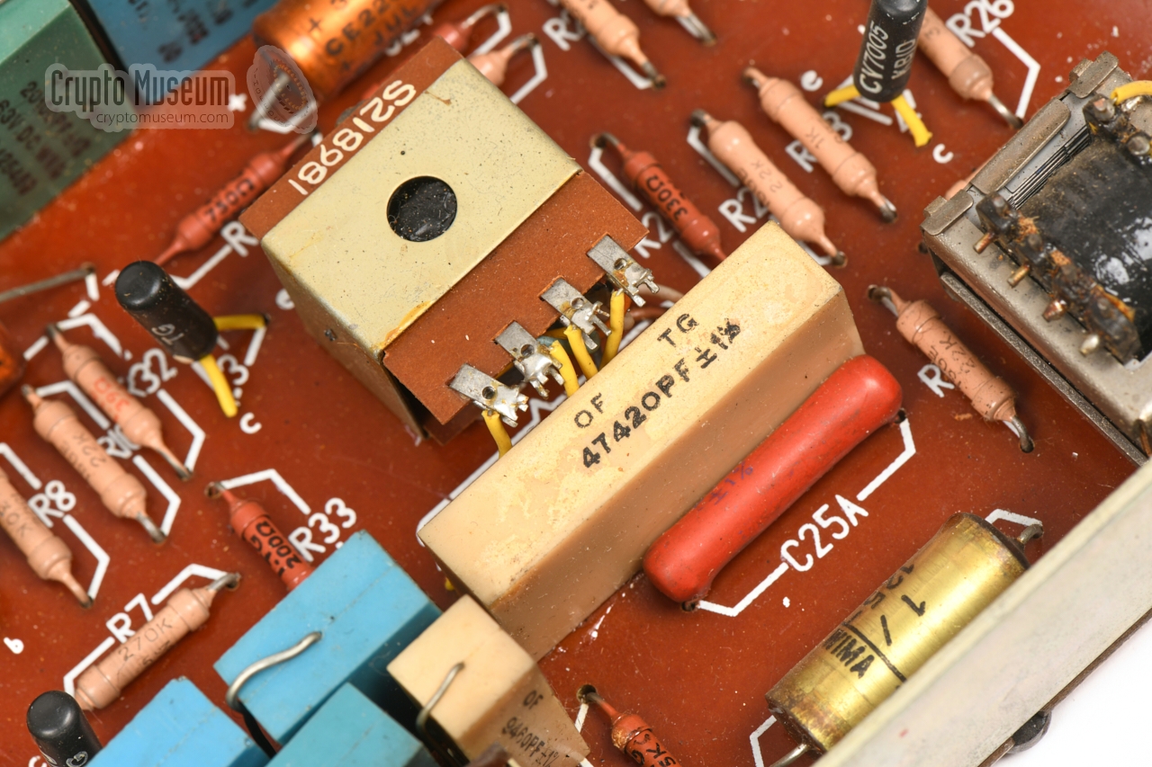
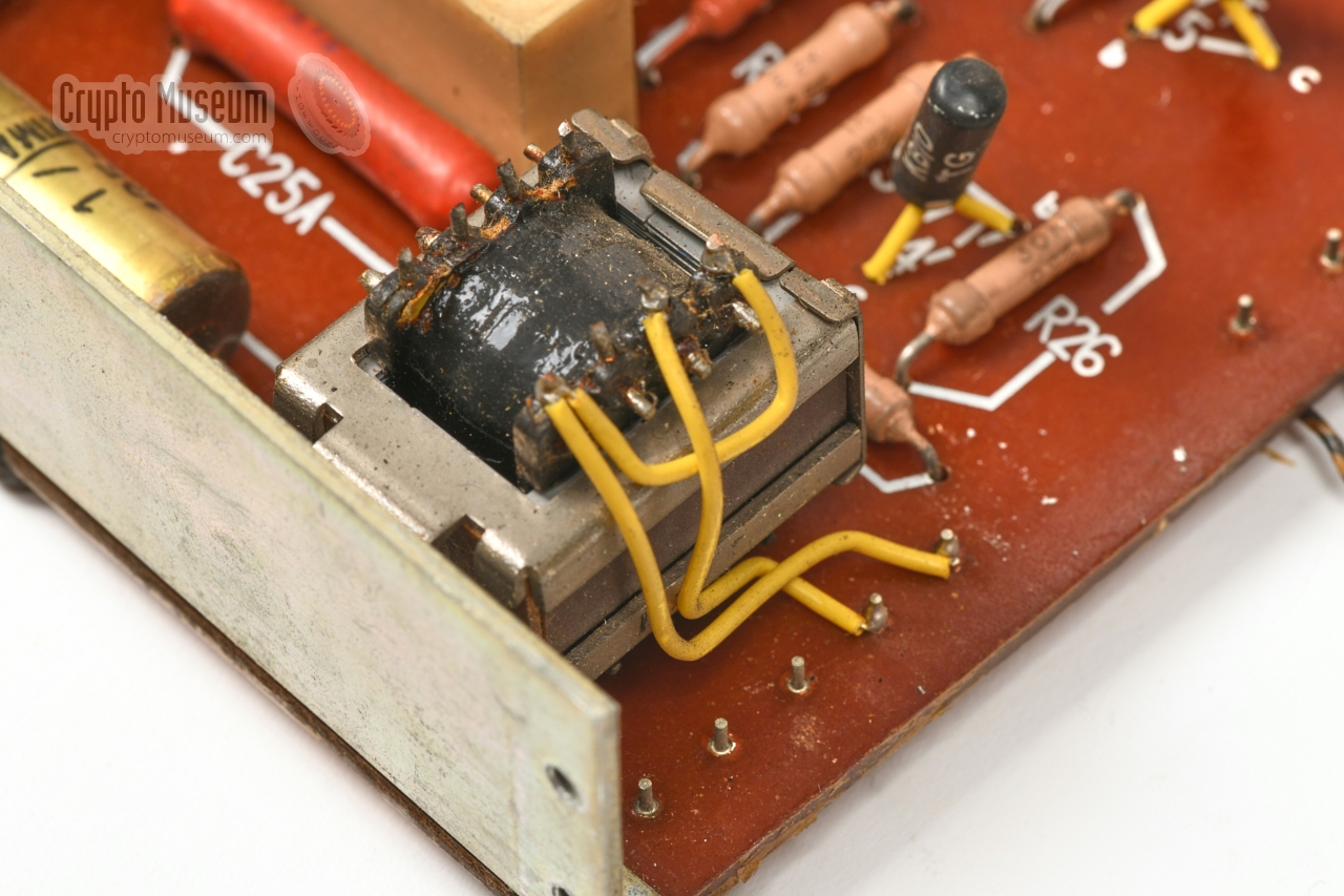
At the center is the 2500 Hz carrier oscillator, which consists of a single
transistor (V3) a tuning coil (L22) and two precision capacitors (C25 and C25a).
The output of this oscillator is injected directly into the ring mixers of the
modulator (transmission) and demodulator (reception).
|
Below is the circuit diagram of the inverter board of the TMC version of
Privacy Set No. 8 as taken down at Crypto Museum in July 2021 from the device
with serial number 1033 and manufacturing code TE 62/1.
At the right edge are the connections to the outside
world, as they are numbered on the PCB. 1 Note that this device has the (+)
side of the power supply connected to the chassis (ground). If we define the
chassis at 0V, this means that the unit is powered by -12V DC.
At the top right is the microphone input. The transformer (T1) is suitable for
various impedances. From T1, the signal is fed
through an 11dB attenuator (A1) followed by a low-pass filter, before it is
applied to the balanced ring mixer around T2, T3 and D1-4.
Here the signal is mixed with the 2500 Hz carrier from the oscillator around
V3, producing upper and lower sideband products.
The lower sideband is the mirrored image of the original voice spectrum.
The signal now passes a second low-pass filter — so that only the lower
sideband remains — and is amplified in a two-stage amplifier (V1, V2), before it
is supplied to the subscriber line via the fork circuit (hybrid) T4.
At the bottom is the receiver circuit. From the fork (T4), the signal passes a
6dB attenuator (A2) and is then applied directly to the demodulator, which
consists of a balanced ring mixer around T5, T6 and D5-8. Like in the
transmission path, this produces upper and lower sidebands.
The result is fed through a low-pass filter, so that only the lower
sideband remains, and amplified in a two-stage amplifier (V4, V5), before
it is supplied to the handset's speaker, via transformer T7.
Note that T7 is a copy of the fork (T4) and has a double function.
In the basic configuration (shown here) it acts as the output transformer
between the reception circuit and the speaker. In case of 2-wire/2-wire
operation however, it can be configured as a 2nd fork circuit,
allowing a standard telephone set to be used instead of a bare handset.
In practice, this option was hardly ever used, as it was difficult to
sufficiently suppress feedback (sidetone) of the scrambled audio.
|
 |
-
When taking down the circuit diagram of this device, it was not possible
to determine the exact layout and wiring of the hybrid transformer (T4)
without damaging the unit. The wiring of the hybrid (fork) is
therefore an educated guess, based on the design of the
Frequency Changer 6AC.
There are several configuration straps to adapt the unit for 150, 300 or
600Ω impedances. It is shown here in the 600Ω configuration.
|
Below is the circuit diagram of the power supply unit, which consists
of two simple rectifiers with stabilisation circuits, but without
a transistor-based regulator. As a result, the voltage on the -12V
rail may vary slightly, resulting in a less stable 2500 Hz carrier signal
from the oscillator.
The mains transformer (T1P) can be configured for virtually any mains
AC voltage, by means of
solder straps at its top. T1P has two
secondary windings: 15V AC for the -12V DC supply of the inverter
board, and 50V AC for the 15 mA current source that provides the
bias for the carbon microphone of the connected handset, and
the line current in a 2-wire/2-wire configuration.
Note that the design of neither PSU circuit is very sophisticated,
as a result of which a rather strong 50 Hz hum is present in
the transmitted signal. This is inherent to the design and was fixed in
later versions like the Privacy Set 9A.
The problem can be fixed in this model, by adding a 22µF/200V capacitor
across the output terminals of the microphone current source.
In the circuit diagram above, this capacitor is shown in grey
(see the description in the Restoration section).
|
|
When we obtained the Privacy Set No. 8 featured here, in September 2018,
it was in working condition. As time progressed however, the audio quality
gradually deteriorated, suggesting problems with the electrolytic
capacitors. Furthermore, a previous owner had fitted a
6-pin Japanese connector
in the space that was originally intended for
the strain relief of a fixed cable.
|
This was probably done as the original wiring was lost, and to allow for
quick (dis)connection. In order to bring it back to its
original state, the aftermarket connector was removed along with its wiring.
It was replaced by original GPO wiring, but due to the fact that the
cut-out had been enlarged to accomodate the connector, we had to add the
improvised bracket shown here. The bracket is completely invisible from
the outside.
At the other end of the cable a 7-pin XLR plug was fitted, wired
per Crypto Museum Standard, so that the device can be used in
various setups.
|
|
|
|
All electrolytic capacitors were swapped for new ones, using the
orange jackets of the old ones as camouflage.
In addition the four 1µF foil capacitors
on the inversion board were swapped for new ones as well, as some of them had
attracted moisture. After reassembling the device, the audio quality was much
better, but the 50 Hz hum – that was noticable before – was still present.
|
Further investigation revealed that it was caused by the poor design of
the 60V DC power supply unit, that delivers the 15 mA current for the
carbon microphone of the handset. Apparently this was a known misfeature,
as it was fixed in later models by adding a 10µF/110V capacitor.
As the hum seriously affected the performance of the scrambler, we
decided to add a 22µF capacitor to the circuit, by soldering it across
terminals 4 and 6 of the connection board on top of the choke coil (L1P).
With the capacitor installed, the transmitter is completely clean.
|
|
|
|
The device is now back in its original state and can be used for
demonstrations. It was tested successfully against the wartime
Frequency Changer 6AC, to ensure that it is interoperable.
The audio quality is excellent and the levels are more than adequate.
Nevertheless, manufacturer EMI later added an extra amplifier in the
transmission path in its 1972 design of Privacy Set No. 8.
|
|
This version of Privacy Set No. 8 exhibits a strong 50 Hz hum in the
transmission path, caused by the poor design of the 60V DC power supply.
This PSU is responsible for the 15 mA DC current that is required for
proper operation of the carbon microphone in the handset of the telephone.
|
This problem can be fixed by adding a 22µF/ 200V capacitor across the
output terminals of the 60V supply, and is best placed between terminals
4 and 6 of the connection block of the PSU, located on top of the
choke coil (L1P).
The diagram on the right shows the layout of the connection block
and the orientation of the capactor. It has the (+) contact on terminal 4.
|
|
|
|
The table below gives the pinout of the screw terminal block inside
Privacy Set 8, 8A, 9 and 9A. This is the lowest row of screws
when looking into the device as shown below. The first column shows
the colours, whilst the second one specifies the contact number inside
the BT20/8 box.
|
Green BT3 Line B 1,2 Black BT6 Line A 1,2 unused Audio in 2 unused Audio in 2 White BT4 Microphone Red BT1 Microphone 3 Blue BT1 Speaker 3 Orange BT5 Speaker Loop wired to 10 Loop wired to 9
|
|
-
In 2-wire configuration the line is connected here.
In 4-wire configuration, this is the Audio out line.
-
Used in 4-wire configuration (e.g. when connected to a radio).
-
Lines (6) and (7) are joined in the connection box (at point BT1).
|
Below is the internal wiring diagram of the
SA 5030 and similar voice terminals.
At the bottom right are the (A) and (B) terminals of the subscriber line.
Directly above it, is the wiring to the terminal block of the Privacy
Set No. 8. The make-before-break (MBB) switches KA (1-4) are part of
the 303/A Key Unit
that is controlled by the 2 (or 3) push-buttons on top of the
voice terminal.
They allow the telephone set to be used for plain as well as secure
calls. In secure mode, the speaker and microphone of the telephone's
Handset No. 164
are routed via the Privacy Set.
The above circuit diagram is for the SA-50xx voice terminals of
WWII, but is also applicable to the post-war modified GPO
Telephone Set No. 710 and 740 units. During the war, the dial
was often omitted from the telephone set — most exchanges were
manually patched — but in the 1960s and 70s most exhanges were
automatically switched. In addition, most wartime installations
were of the Local Battery type (LB), whilst the post-war systems
were generally Central Battery (CB).
|
To allow the Privacy Set and suitable telephone sets to be tested, used
and demonstrated in various configurations, without altering the fragile
vintage wiring of the devices all the time, Crypto Museum has defined its own
standard, involving inline 7-pin male/female
XLR connectors.
In this standard, an 8-point junction box BT 20/8 is used as the
central hub. The SA 50xx voice terminal is fitted to the BT 20/8 via
a fixed 8-wire braided cable. The subscriber line is also fitted to the
BT 20/8 via a fixed 2-wire or 4-wire braided cable, whilst a fixed
7-wire braided cable with an XLR7/F connector
at the end is present for quick (dis)connection of the Frequency Changer.
The Privacy Set itself is fitted with a fixed 7 or 8-wire brown PVC cable
with an XLR7/M connector at the end. This allows the Privacy Set
to be disconnected from the setup without opening it and unscrewing the
wires from its terminal block or from the
BT 20/8 box.
Below is the pinout of the XLR7/M connector that is fitted to the end of the
fixed cable of the Privacy Set. The wiring order is identical to the
order on the terminal block inside the
predecessor — Frequency Changer 6AC.
|
Line (B) green Line (A) black - LB (or unused)
Microphone (H) white Microphone (L) red Speaker (L) blue Speaker (H) orange
|
|
Type Voice scrambler Principle Single frequency inversion Manufacturer TMC Batch code TE 62/1 Product code E526539/1A Carrier 2500 Hz Impedance Standard telephone line at 150, 300 or 600Ω Terminal Modified conventional analogue telephone set or bare handset Dimensions 255 × 155 × 90 mm (305 × 155 × 90 mm including mounting flanges) Weight 4520 grams
|
|
|
|
Any links shown in red are currently unavailable.
If you like the information on this website, why not make a donation?
© Crypto Museum. Created: Wednesday 26 May 2021. Last changed: Wednesday, 05 November 2025 - 11:55 CET.
|
|

|
|
|


![Block diagram of Privacy Set No. 8. Click to see the original drawing [1].](files/ps_block.jpg)


