|
|
|
|
|

|
|
UK Phone Voice Scrambler Overview → ← 710
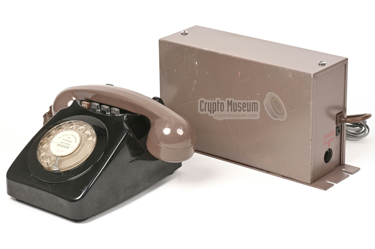
The image on the right shows a Telephone No. 740 that was recovered
from a GPO facility in Northern Ireland together with a
Privacy Set No. 8,
shortly after the facility had been bombed [2].
The device consists of a black body with a brown handset, and has all
four push buttons fitted. 1 The leftmost push-button is brown 2 and is
marked SEC'T, which is short for SECRET. When pressed, it connects the
subscriber line and the
microphone and speaker of the handset directly to the Privacy Set.
The other 3 knobs are clear
and read MAIN, RECALL and EXTN respectively.
|
|
|
Telephone No. 740 was introduced in 1968 as the successor to the 1964
Telephone No. 710. It is largely identical, but has an improved enclosure
and circuit board. Furthermore, it allows up to four push-buttons to be
fitted in the space above the dial.
The device shown here has all four push-buttons fitted and carries
manufacturing code GEN 73/1 at the bottom, which means that it was
manufactured by GEC-AEI Telecommunications
in Newton Aycliffe in County Durham (UK).
The modified 740 is compatible with all types of
Privacy Set No. 8/8A and No. 9/9A,
but also with the earlier wartime valve-based
Frequency Changer No. 6.
Privacy Sets were used on public subscriber lines until at least 1978,
after which they were succeeded by more secure alternatives.
|
 |
-
At least two buttons are needed for the Privacy Set.
The other two are optional.
-
Originally, all push-buttons for the 740 had clear caps, so that they
could be used with any combination of case and handset colour. The brown SEC'T
button is therefore a little out of place, as it stems from the earlier
710 range. It might have been used when clear SEC'T buttons where in
short supply.
|
The image below show a complete GPO Telephone No. 740, ready for connection
to Privacy Set No. 8 or a compatible device. It
is fitted with a black 10-wire cable that terminates in a BT37B junction box.
The Privacy Set is also connected to the junction box, via a 7, 8 or 10-wire
cable.
Also connected to the junction box, is a 2 or 4-wire subscriber line.
In the default situation, the subscriber line is connected to the 740, which
acts as a regular telephone set.
Once a call has been established and the handset is off-hook,
both parties press the SEC'T button on their 740. The
device then becomes the voice terminal of the
Privacy Set and the conversation is scrambled.
In this situation, the 740 has become the voice terminal of the Privacy Set.
The subscriber line is disconnected from the telephone's
line circuit and passed to the line input of the Privacy Set.
In the same vein, the microphone and speaker of the telephone's
handset are disconnected from the telephone circuits and connected directly
to the voice circuits of the Privacy Set. By mounting an XLR7/M connector
at the end of the brown cable
(wired according to our own standard),
we are able to demonstrate the 740 in combination
with any GPO telephone scrambler in our collection.
|
|
The interior of the device can be accessed by loosening a single screw
at the centre of the rear side, after which the plastic shell can be
pulled over to the front, whilst the knobs of the push-buttons (optional)
remain inside the shell. The shell catches the bottom panel at the front edge.
|
The image above shows the interior of the device after the case shell has
been removed. All parts are mounted to the metal base. At the bottom are the
bell set and a printed circuit board (PCB).
Integrated with the PCB is a U-shaped metal bracket that controls the
hook switch (gravity switch in GPO terminology) and up to 4
push-button switches. Mounted between the bell set and the U-shaped bracket
is the circular dial.
At the rear edge of the PCB are a series of screw terminals to which the
handset, subscriber line and any (optional) switch packs are connected.
|
|
|
|
The image above shows the interior of the device as seen from the rear.
The wiring appears a bit messy, but this is an unavoidable side effect
of the modification to make the 740 suitable for use with a Privacy Set.
At the rear edge of the bottom panel are the cable inlets for handset and line.
|
The handset is connected via a brown 4-wire coiled cable, whilst a black 10-way
cable is used for connection of subscriber line and Privacy Set.
This is different from the usual 4-wire cable.
The difference between a regular 740 device and a Privacy Set voice terminal,
is the addition of the 4K switch pack (1/DSP/1244) shown here in the leftmost
position (seen from the rear).
When the SEC'T button is pressed, this switch is activated and remains locked
in position until released by pressing another button. It is also released when
the user put the handset in the cradle (on-hook).
|
|
|
|
The 4K switch pack consists of 4 individual changeover contacts, one of which
is used to transfer the subscriber line to the Privacy Set. The remaining
contacts disconnect the microphone and speaker from
the device and connect them directly to the voice circuits of the Privacy Set.
The 4K switch is wired to the unused screw terminals on the PCB and to an
extra set of 6 screw terminals that it
fitted to the side of the U-shaped bracket.
From there it is patched to the 10-wire cable.
|
|
The Telephone No. 740 featured on this page was recovered – together
with this Privacy Set No. 8 – from a GPO facility
in Northern Ireland, shortly after it had been bombed by the IRA [2].
When we received it in July 2021, it came with partial wiring and
was in an unknown and untested state.
|
After a first inspection it became clear that someone had previously attempted
to rewire the unit – probably for use on the public switched network or on a
PABX – as a result of which the junction box (BT37B) was wired incorrectly.
This was easily fixed however, by inspecting the
740 circuit diagram and tracing the
wiring from the 4K switch pack under the SEC'T button.
Once the wiring was corrected, an 8-wire cable with an
XLR7/M connector was added for connection of the
Privacy Set,
and a 2-wire cable with an RJ11 connector
for the 2-wire subscriber line.
|
|
|
|
After testing the device on the local PABX with a known good telephone set
at the other end, it became clear that the audio in the receiver circuit was
rather faint. This was solved by replacing the 4T speaker element in the
handset. The unit was tested again and produced clear audio.
|
The next problem to be solved was the fact that the push-buttons were binding.
It was difficult to press them down and some buttons were not always released
when another one was pressed.
The image on the right shows the 4 positions of the push-buttons as seen
from the rear. There are 4 white nylon plungers that are pushed down by
each of the buttons. In this image, only two of them control a switch.
The other 2 are only used to release the large 4K switch pack, but as they
are unsupported, this does not always work as expected.
It would be better if they had a switch.
|
|
|
|
The binding problem appeared to be caused by ageing of the parts. It was solved
by smoothening and greasing the white plungers. Furthermore, a dummy switch was
mounted behind the 2nd plunger (connected to nothing), so that it now properly
releases the SEC'T button when pressed.
Finally, the unit was tested with a compatible scrambler at the far end of the
telephone line.
|
- Block Terminal incorrectly wired
- External wiring incomplete
- Dial outer ring loose
- Faint incoming audio
- Push-buttons binding
- One push-button knob broken
- Cover missing from block terminal BT37B
|
- Cover for block terminal BT37B
|
To allow the Privacy Sets
and suitable telephone sets to be tested, used
and demonstrated in various configurations, without altering the fragile
vintage wiring of the devices all the time, Crypto Museum has defined its own
standard, involving inline 7-pin male/female
XLR connectors.
In this standard, an 25-point junction box BT-37B is used as the
central hub. The GPO 740 voice terminal is fitted to the BT-37B via
a fixed black 10-wire PVC cable. The subscriber line is also fitted to the
BT-37B via a fixed 2- or 4-wire cable, whilst a fixed
8-wire cable with an XLR7/F connector at the end is present for
quick (dis)connection to the Privacy Set
or Frequency Changer.
The Privacy Set itself is fitted with a fixed 7- or 8-wire PVC or
braided cable with an XLR7/M connector at the end. This allows the
Privacy Set to be disconnected from the setup without opening it and
unscrewing the wires from its internal terminal block or from the
BT-37B junction box.
Below is the pinout of the XLR7/F on the cable that is fitted to the
BT-37B terminal block.
|
- Line (B)
- Line (A)
- LB (or unused)
- Microphone (H)
- Microphone (L)
- Speaker (L)
- Speaker (H)
|
|
- N840, Telephone No. 740 circuit diagram
GPO, 18 February 1969 - 12 Actober 1972. Issue A (1 page). 1
- N4700, Auxiliary Units and Additional Parts for 700-type Telephones
GPO, 12 August 1963 - 15 May 1977. Issue C (4 pages). 1
- N848, Auxiliary units for Telephones, Nos. 710, 711, 740, 741 & 746
GPO, 21 January 1969 - 9 May 1977. Issue J (4 pages). 1
- Press-Buttons for Tel. No. 710, 711, 740, 741 & 746
GPO, 10 February 1969 - 28 July 1980. (2 pages). 1
|
-
Document obtained via [1].
|
- Robert Freshwater, Telephone No. 740
Bob's Telephone File (website).
Retrieved August 2021.
- Richard P., GPO Telephone No. 740 - THANKS !
GEN 73/1 version, modified for use with Privacy Set. Received July 2021.
|
|
|
|
Any links shown in red are currently unavailable.
If you like the information on this website, why not make a donation?
© Crypto Museum. Created: Monday 09 August 2021. Last changed: Tuesday, 10 August 2021 - 13:58 CET.
|
|

|
|
|