|
← Germany WWII Abwehr
Abwehr spy radio transmitter
S-90/40 was a clandestine
40 Watt short-wave (SW) radio transmitter, developed
around 1939 at OKW-Aussenstelle Berlin-Stahnsdorf 1 (Germany)
for use during World War II (WWII)
at the central control stations (Köpfe) 2
of the German Intelligence Service,
the Abwehr, and its foreign counterparts.
From 1942 onwards, the transmitter was produced by OKW Aussenstelle Wurzen
[1].
|
The S-90/40 was commonly used as part of a complete
SE-90/40 spy radio set
– housed in a black suitcase – along with the E-90 receiver, but it was
also deployed as a standalone transmitter, for example in Abwehr base
stations.
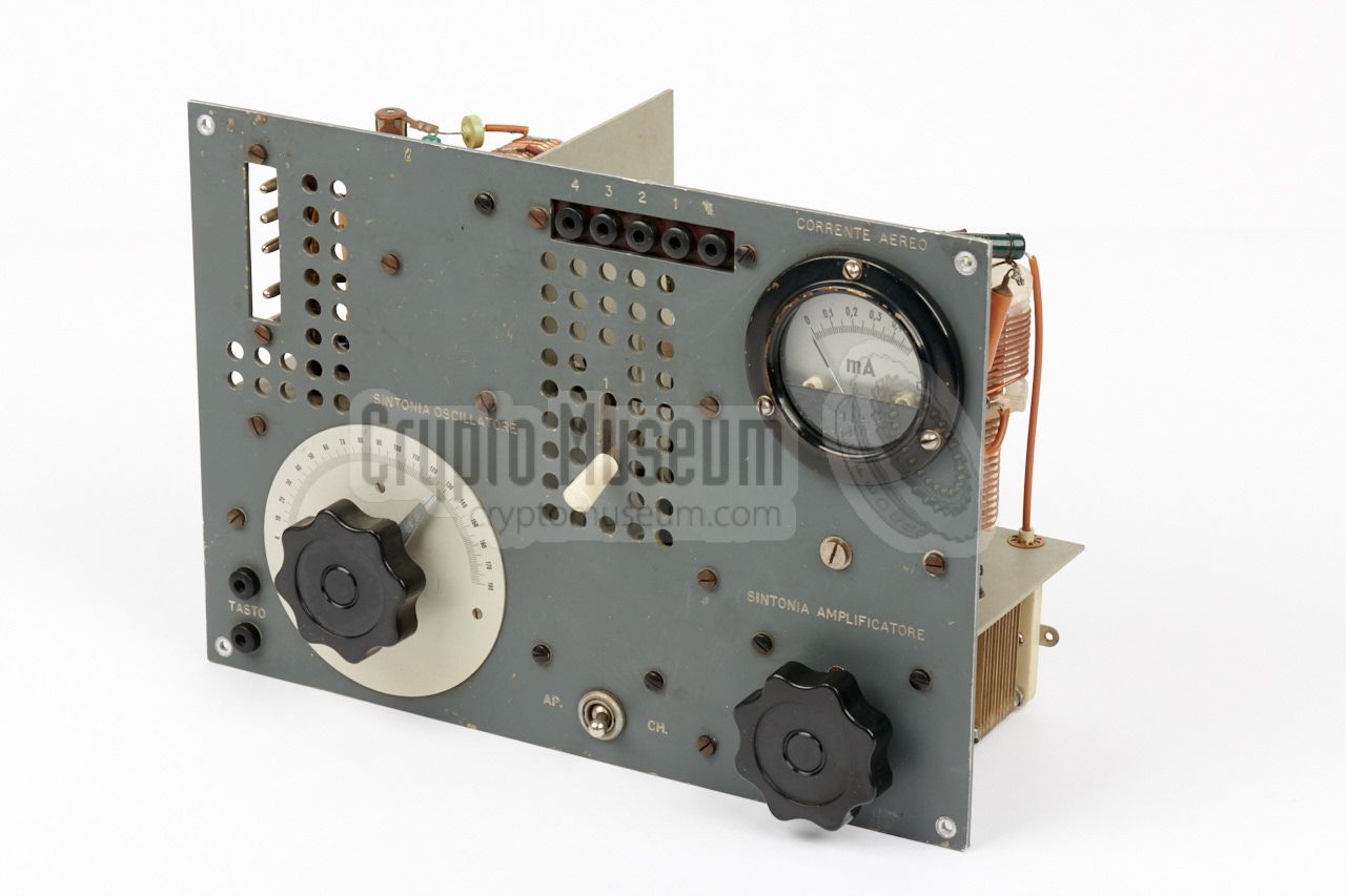
The image on the right shows a typical S-90/40 transmitter
with serial number 2. It has Italian
text on its front panel, which suggests that it was intended for use by the
Italian equivalent of the Abwehr — the
Servizio Informazioni Militare (SIM) 3 .
The design of the S-90/40 transmitter was later copied by the Italians as the RN-6.
|
|
|
|
When used as a standalone transmitter, it was commonly used in conjunction
with an existing HF receiver, such as the Siemens R-IV
or the Radione R3.
The device is housed in a dark grey metal enclosure that measures
27.5 x 19.5 x 10.5 cm and weighs 3128 grams.
It should be powered by an external power supply unit (PSU)
that provides 12.3V AC (LT) for the filaments and +700V DC for the
anode of the RL12P50 valve (tube) of the power amplifier (PA).
The device is suitable for CW (morse) only and has a freely adjustable
oscillator (VFO) built around a CC2 valve.
|
 |
-
OKW = Oberkommando der Wehrmacht (Supreme Command of the Armed
Forces) in Nazi Germany during the Second World War.
Aussenstelle = Outpost.
-
In German known as Funkmelde-Köpfe (radio message head-end stations).
These were fixed Abwehr stations (such as Wohldorf-Hamburg) or temporary
(mobile) stations for a specific operation.
-
The Servizio Informazioni Militare (SIM) was Italian's military intelligence
organisation from 1900 to 1949. During WWII, it was fascist dictator Benito
Mussolini's equivalent of the German Abwehr.
|
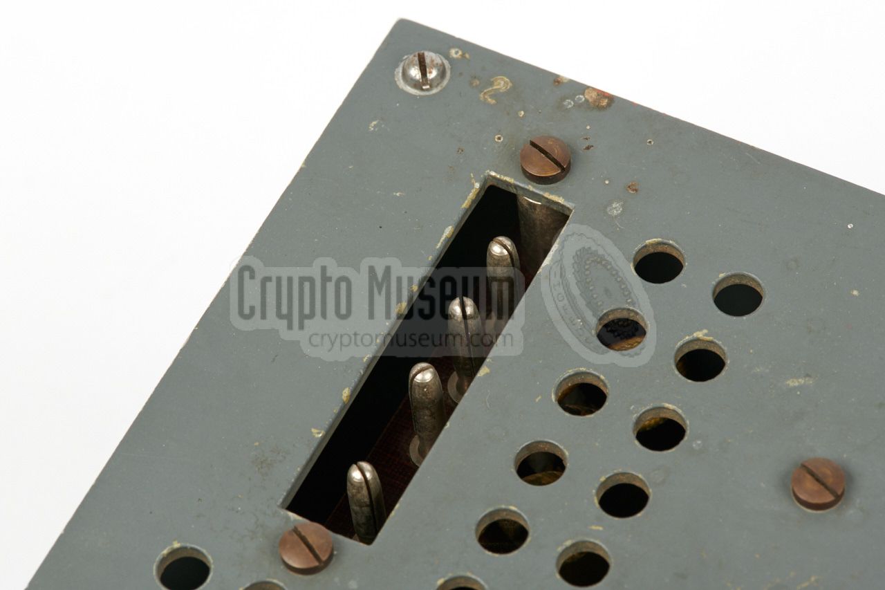
All controls and connections of the S-90/40 are located at the front
panel, which is shown in the diagram below. At the top left is the socket
for the power supply unit (PSU). At the top right is the antenna current
meter, with the antenna sockets to its left. The antenna should be connected
to the rightmost socket (T) and to one of the other sockets (1-4).
At the bottom left is the frequency dial of the free-running variable
frequency oscillator (VFO), which has a liniar scale from 0-180°.
A standard morse key can be connected to the banana sockets
at the bottom left.
Once the desired frequency is set, the PA tuning knob at the bottom right
should be adjusted for maximum power output, using the antenna current meter
at the top right as an indicator. On some versions an extra meter adjustment
is present between the meter and the PA tuning knob.
The white lever at the centre is used to select the required frequency
band (1) or (2). The basic model runs from 3.5 to 8.5 MHz, but other
frequency ranges have been found as well, such as 5.3 to 9.3 MHz [1].
|
Although the S-90/40 was sometimes used as a standalone transmitter, it was
developed specifically for the SE-90/40 spy radio set
shown in the image below.
The set is housed in a rectangular suitcase covered with black book linen.
Inside the suitcase are three compartments: one towards the rear for the mains
power supply unit (PSU) and the ancillaries, one at the front left that holds
the E-90 receiver,
and one at the right that holds the S-90/40 transmitter.
The image below shows an unknown Abwehr radio station in which two
Siemens R-IV receivers
are clearly visible. The one at the right has the power supply
unit on top, whilst the one at the left has two plug-in units on top.
In between the receivers are two Abwehr transmitters: an S-89/80, with
the smaller S-90/40 placed on top.
Thanks to Jørgen Fastner for supplying this picture [4].
According to contemporary witness Rudolf Staritz [5],
the setup shown in the picture above is rather unusual,
as it was common practice with the Abwehr to keep transmission
and reception stations apart, often at two different locations. Nevertheless,
the S-90/40
and S-89/80 were used exclusively by the Abwehr.
In this case they were issued alongside the
Siemens R-IV receiver.
The photograph above is from an unknown source, but is thought to show the radio
room at Ast (Abwehrstelle) Oslo during WWII. At the left is a
Siemens R-IV receiver with a plug-in module
on top. To its right is an Abwehr E-90 receiver and an S-90/40 transmitter
both placed on top of the accompanying power supply unit (PSU).
The fact that the setup is very similar to the one in the photograph above it,
gives rise to the thought that they might have been taken at the same place.
|
The transmitter of the Italian RN-6 spy radio set was a clone of the S-90/40.
The circuit is nearly identical and is built around the same valves (CC2 and RL12P50),
albeit complemented by Italian components. The RN-6 was made by Nova Radio
in Milan shortly after the introduction of the
Abwehr's SE-90/40 spy radio suitcase set.
The image on the right was kindly supplied by Antonio Fucci and shows the interior
of the RN-6 transmitter in his collection [6].
|
|
|
|
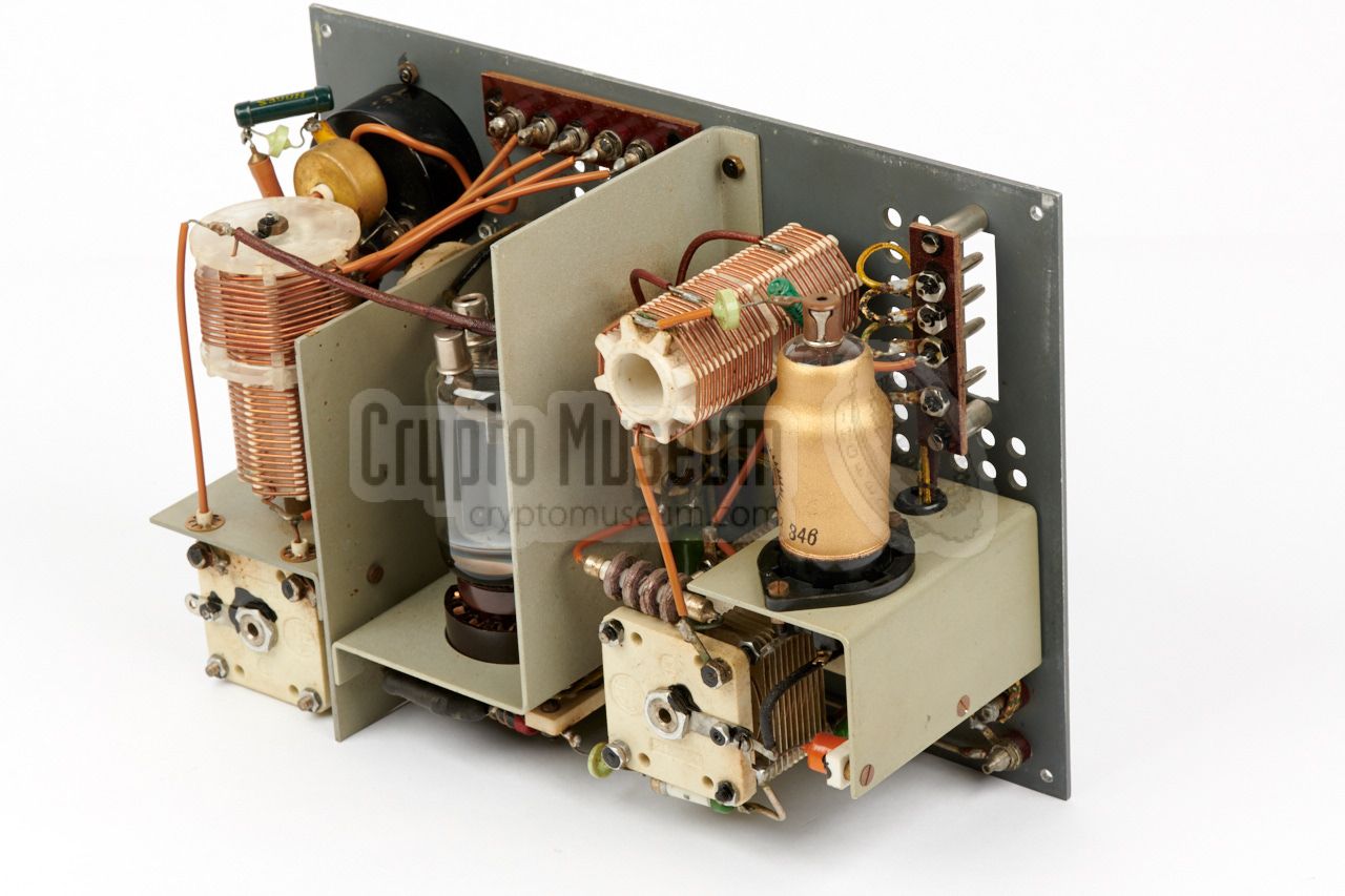
The interior of the S-90/40 can be accessed by loosening the four large bolts
at the corners of the front panel, after which the
front panel can be lifted
from the metal case shell. All internal parts are mounted to the front panel,
which is actually a metal frame divided in two compartments.
|
The smallest compartment – here visible on the right – contains the freely adjustable variable frequency oscillator (VFO),
built around a CC2 valve, a large coil and an
adjustable capacitor.
The larger compartment contains the power amplifier (PA), which is built
around an RL12P50 valve that is powered at +700V and delivers an HF power
output of 40 Watts. It also has a large coil and a large adjustable capacitor,
but the latter is mounted on a Pertinax panel, so that its axle is isolated
from the chassis. The antenna is connected to a gavanically separated
tank coil.
|
|
|
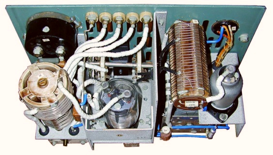
Five banana sockets are present at the front panel for connection of the
antenna, of which socket (T) is the common rail. The other sockets (1-4)
are each connected to different taps on the tank coil. The wire to socket (1)
passes through a current transformer, so that the meter on the front
panel can be used to measure the antenna current when tuning the transmitter
for maximum power output. The image above shows the interior of the S-90/40
as seen from the bottom.
|
Below is the circuit diagram of the S-90/40 with serial number 2.
Note that a number of different version of this transmitter were produced,
in particular for different frequency ranges and with a different antenna output
circuit. The diagram shown here is of the so-called 'tropicalized'
variant of the S-90/40, and is based on the
wartime circuit diagram
published by Rudolf Staritz [2].
At the left is a free running oscillator (VFO) built around a CC2.
Note the two orange 100 pF temperature-compensated capacitors in the
tuned circuit.
The output of the oscillator is fed to the g1 of the PA valve (RL12P50)
via a 20 pF capacitor and a 10 ohm resistor with 5 windings.
Also note that the centre contact of the variable capacitor in the
tuned circuit of the PA is not connected to ground as is
usually the case. Instead the axle is isolated with the Pertinax plate.
|
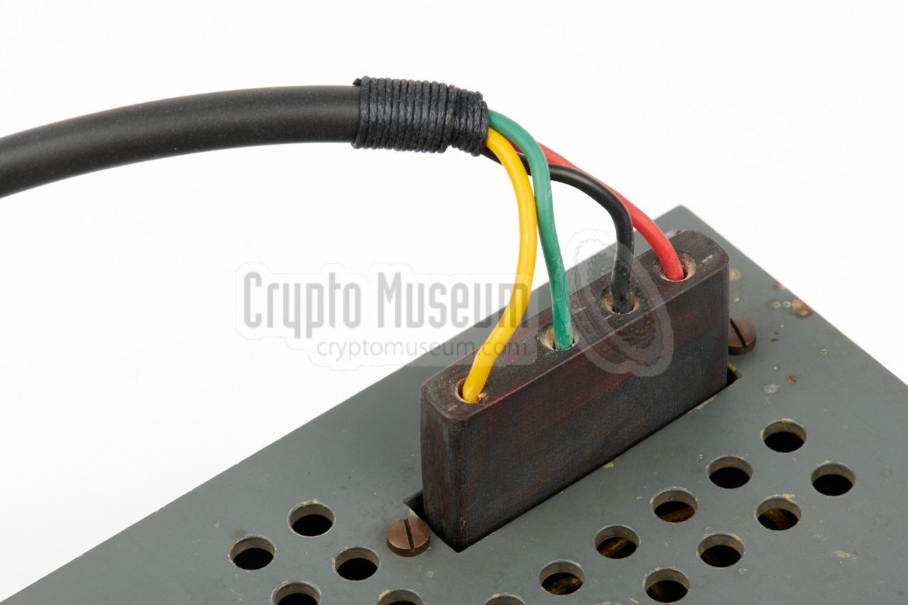
The transmitter is powered by an external power supply unit that must
be connected to the 4-pin socket at the top left of the front panel. Only two
voltages are needed: 12.3V for the filaments (LT) and +700V for the anodes
of the valves (HT). The pinout of this socket is a s follows:
Finding a suitable connector for this socket can be very difficult, as they
were probably purpose-built at the time. As a gap-fill solution it is
possible to use female banana plugs and place them over the pins in the
socket. The best solution however, would be to make a replica from era-correct
materials. Below are the dimensions of the plug (in mm). The body
is made of pertinax.
➤ Download drawing as PDF
|
WARNING —
When inserting or removing the power plug, be careful not to touch the
screws at the front side of the plug as they carry a high voltage that will
cause a serious – and potentially harmful – shock. This may also be the case
after the external power supply unit has been switched off or disconnected,
as the capacitors inside the S-90/40 transmitter may still be charged.
Always hold the plug by the short sides.
Below are the connections of the valves as seen from the bottom (the solder
side) of the sockets. At the far right is the RL12P50 power amplifier valve, which
has two contacts at the top: one for the g3 (connected in parallel to
the g3 contact at the socket) and one for the anode (a).
➤ CC2 datasheet
➤ RL12P50 datasheet
|
HT voltage 700V DC LT voltage 12.3V AC Output power 40 W Valves CC2, RL12P50 Stages Oscillator, Power Amplifier (PA) Frequency 3.5 - 8.5 MHz Tuning Variable Frequency Oscillator (VFO) Antenna Symmetrical dipole (wire) or long wire with counterpoise
|
-
Obtained from Frank's Electron Tube Pages [7].
|
- Louis Meulstee, S 90/40
Wireless for the Warrior, Volume 4, Supplement, Chapter 117.
Retrieved May 2018.
- Rudolf F. Staritz, Original S-90/40 circuit diagram
Obtained via [1].
- Wikipedia, Servizio Informazioni Militare
Retrieved May 2018.
- Photograph of Siemens R-IV and Abwehr transmitter in unknown Abwehr station
Jørgen Fastner Collection. Obtained May 2017. Reproduced here by kind permission.
- Rudolf Staritz, Personal correspondence
June 2017, via Arthur Bauer.
- Antonio Fucci, Image of Italian RN-6 transmitter
Retrieved May 2018. Reproduced here by kind permission.
- Frank Philipse, Valve datasheets
Website: Frank's Electron tube Pages.
|
|


![SE-90/40 spy radio set in black suitcase. Photograph via [1].](img/se90_suitcase.jpg)
![Abwehr S-90-40 abnd S-89/80 together with Siemens R-IV receivers, in an unknown Abwher station. Jřrgen Fastner Collection [4].](../../df/siemens/r4/img/siemens_r4_jf_large.jpg)