|
|
|
|
|

|
|
Teltron Scambler
Secure voice frequency inverter
- under construction
The SP-612 was a secure voice encryption unit,
based on the principle
of frequency inversion, developed and built by
Teltron
in München (Germany) around 1985.
The design is based on an FX-204 single-chip frequency inverter
[2] and was mainly sold to the German police and other law enforcement agencies. It is also known as a
voice scrambler or frequency inverter
[1].
|
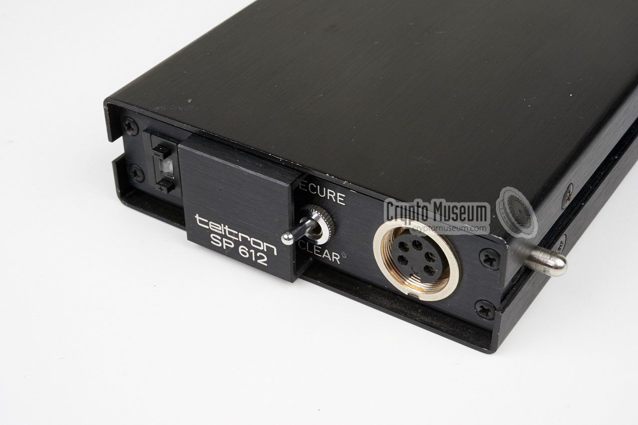
The device measures 17 x 10 x 3 cm and was pretty small for
the era. It was usually mounted in a metal bracket that was fixed inside,
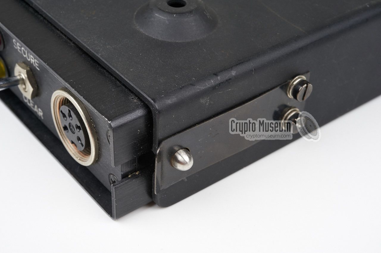
say, a police car. The SP-612 was held in place by two springs that locked
onto the pins at both sides of the front panel. This way the device could
easily be removed for repair or maintenance.
A small sliding 'door' at the left of the front panel, gives access to
a single-digit code settings with up and down buttons.
The SP-612 offered very limited security as it only had 16 possible code
settings (0-9 and A-F).
|
|
|
The device was further 'weakened' by the fact that it only provides
frequency inversion and not time-domain scrambling as in later devices,
such as the SP-850.
Eavesdroppers could easily recorver the clear
speech by using a freely adjustable frequency inverter.
|
Connecting and operating the SP-612 was relatively simple.
The device was connected to the wiring of the (police) car and the existing
radio via the sliding bracked that mated with the 15-pin connector at
the rear of the unit. Once installed in the bracket, the handset
would be connected to the 5-pin 270° DIN socket at the front panel.
A toggle switch is ued to select between SECURE and CLEAR modes
and two indicators, a red and a yellow one,
show the present state of the unit.
The SP-612 offers 16 different security codes to be selected with
a single-digit selector that is hidden behind the sliding 'door' at the
left. Sliding this door to the right, reveals the selector. It can be
set to 0-9 or A-F. Once the code is set, the door is placed in the leftmost
position again.
|
|
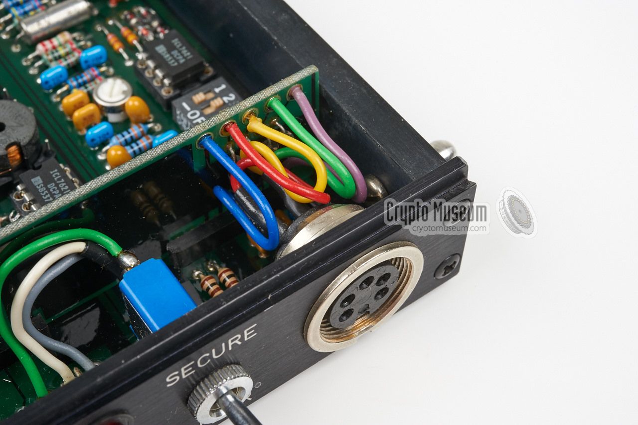
The SP-612 is housed in a slim-line aluminium enclosure that consists
of a frame and two case shells. Each case shell is held in place by two
screws at either side. After removing the screws and taking away the
two shells, the well-organised interior is exposed as shown in the images below.
|
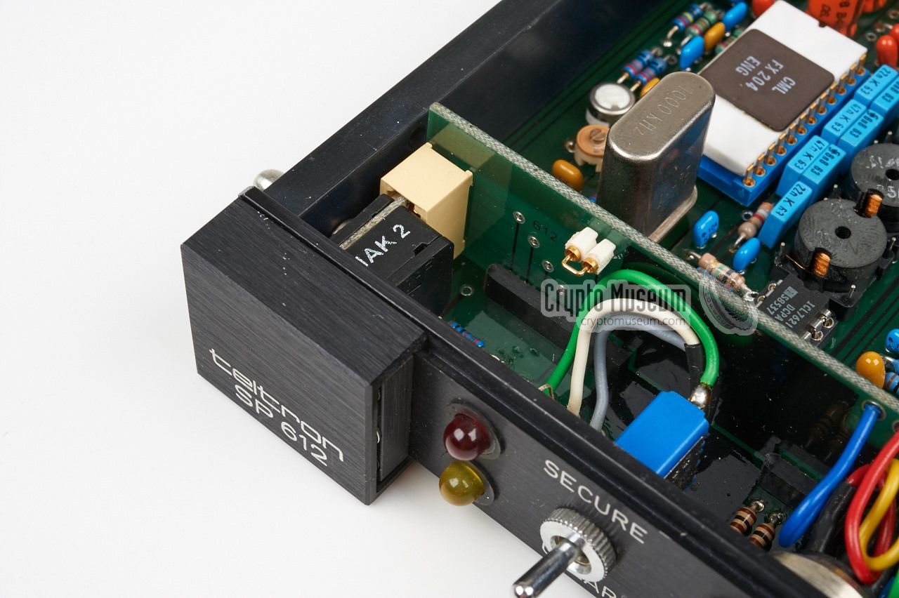
The device contains one large PCB with all parts mounted on one side,
plus a smaller one for the controls and connections. The
larger PCB is
mounted horizontally and occupies most of the interior.
The design is based on the
FX-204 single-chip frequency inverter
made by CML, that is prominently visible at one of the edges.
The SP-612 is well-built and neatly organised, using only first class
components. All ICs are socketed, and the solder side of the PCB is
freely accessible, making it a service friendly device.
|
|
|
-
VSB = Variable Split Band.
|
|
|
|
Any links shown in red are currently unavailable.
If you like the information on this website, why not make a donation?
© Crypto Museum. Created: Saturday 02 July 2016. Last changed: Sunday, 04 January 2026 - 15:35 CET.
|
 |

|
|
|