|
|
|
|
|

|
|
Philips ZODIAC BVO-T → ← Mucolex
|
|
BVO-M
UA-8244 · KY-6127/M
|
|
|
Trunk encryption device · Mucolex II
BVO-M was a Trunk Encryption Device
(Dutch: Bundel Vercijfer- Ontcijferapparaat), 1
developed around 1981 by Philips Usfa in Eindhoven (Netherlands)
for the Royal Dutch Army. The device was used as part of the
ZODIAC 2 integrated communications network,
and was installed in the fully automated (mobile) telephone exchange.
It allows multiplexed traffic to be transferred at speeds up to 2 Mb/s
and is backward compatible with the older
1 Mb/s Mucolex encryption device.
The BVO-M is also known as UA-8244, KY-6127/M, Mucolex II
and NSN 5810-17-055-9446.
|
BVO-M allows voice and data to be bundled, encrypted and sent over
a line-of-sight radio link (LOS). Several BVO-M units were typically
installed as part of the ZODIAC/DELTACS
automated switch, 3 developed by Philips daughter HSA.
A number of such complete switches were implemented as mobile installations,
allowing the fast deployment of flexible field networks.
Two versions of the BVO were available, named BVO-M and BVO-T.
The image on the right shows a typical BVO-M, which is backward compatible
with the earlier 1 Mb/s MUCOLEX.
|
|
|
|
BVO-M was part of the ZODIAC communications network of the Royal Dutch Army,
a project that started in 1975 and was completed in 1987. In the early 2000s,
ZODIAC was gradually replaced by TITAAN, but BVO-M remained in use in the first
stages of the implementation. The last units were decommissioned
in 2007, which means that BVO-M had a life cycle of more than 20 years.
|
-
Literally translated: trunk encryption/decryption device.
-
Formerly known as DELTACS.
-
Also known as a telephone exchange or exchange switch or
switched network.
|
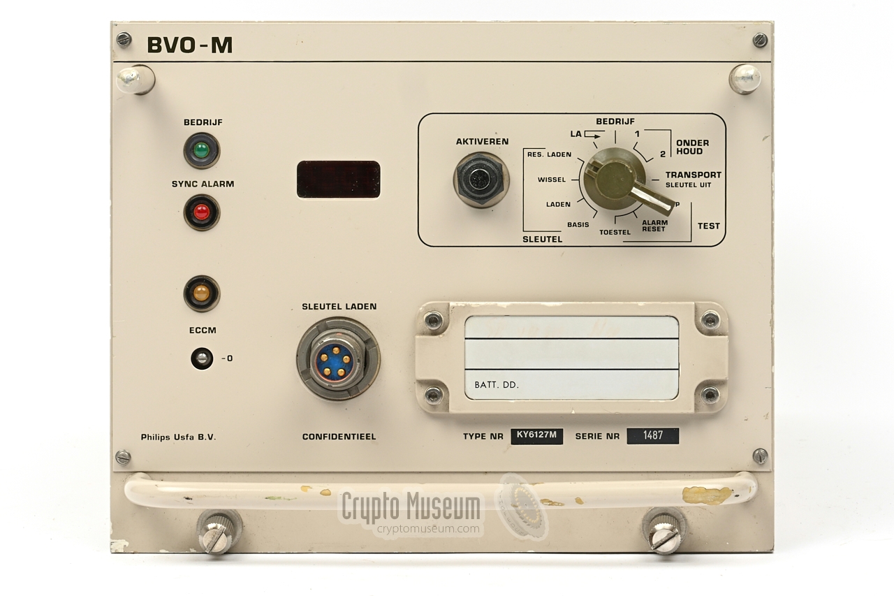
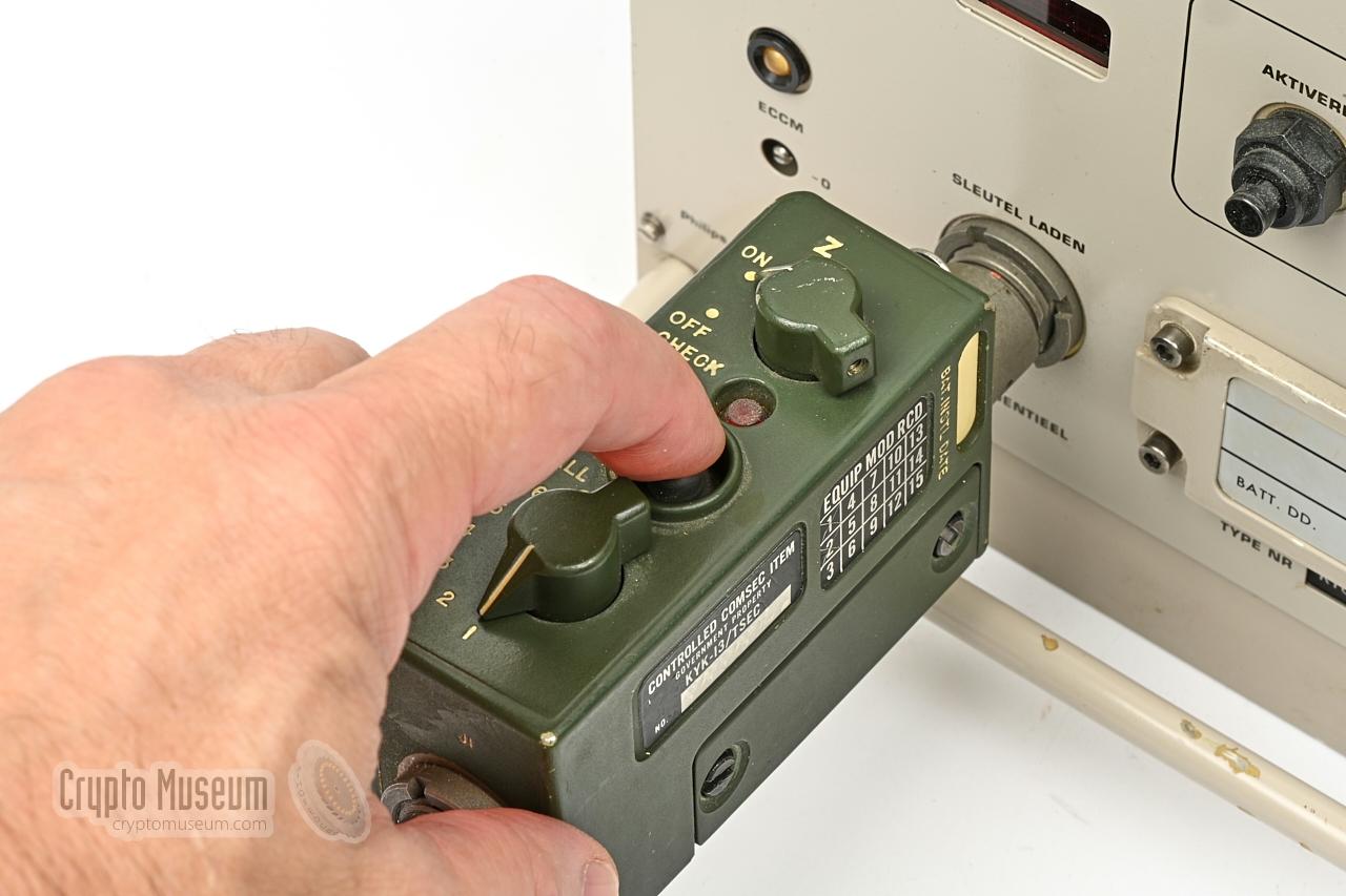
The image below provides a quick overview of the features of the BVO-M.
The device measures 300 × 200 × 150 mm and weighs approx. 8.5 kg. All controls
and indicators are at the front panel. Also at the front are a U-229 socket
for connection of a DS-102
compatible key transfer device, and a
backup battery
for retaining the crypto variables (keys) in the CMOS memory.
The keys can be purged (ZEROIZED) remotely.
The power, red and black
connections are at the rear.
The device has several modes of operation,
such as key loading (sleutel
laden) and operation (bedrijf). The desired MODE must be selected with
the knob at the top right, and is activated by pressing the ACTIVATE button
(activeren). The display shows the current operating state.
|
- Power supply off: backup battery off, keys destroyed, ready for transport.
- Test display and indicator LEDs. Display shows
**** 0000 :: - Simulate alarm. Display shows
AL . - Load the base key into the operational crypto variable register.
- Crypto variable (from fill device) is loaded as spare key.
- Initiate key change (required at both ends). Display shows
SL W . - Load spare crypto variable into spare crypto variable memory.
R+SL . - Puts the equipment in normal crypto operation mode.
- Activate internal test loop.
- The crypto start pattern is transmitted once.
- Internal test of the equipment. Display shows test number.
|
Green Valid keys loaded, in-sync and BEDRIJF (OPERATION) is selected Red Sync ALARM Yellow ECCM units at both ends have been switched on
|
- No keys loaded (flashing when zeroized)
- Base key loaded (in operational key register)
- Base key and spare key loaded
- Spare key loaded
- Crypto variable changed (spare key in operation)
- Operational and spare key loaded
- Compromise pattern recognised twice
- The quipment is in ALARM state
- Normal operation (flashing when command is executed)
- Local test initiated
- Local test is being carried out
- Local test carried out without a fault
- Fault in equipment
- LA loop test switched on
|
|
|
Display during maintenance (onderhoud 2)
|
|
|
- Set detection time for sync (A-F) and set acquisition time (00-09)
- Test number
- End of test, no faults found
|
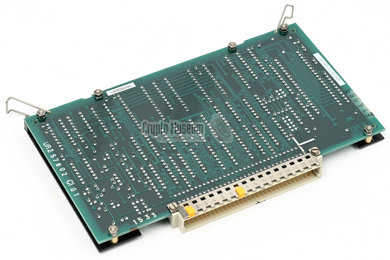
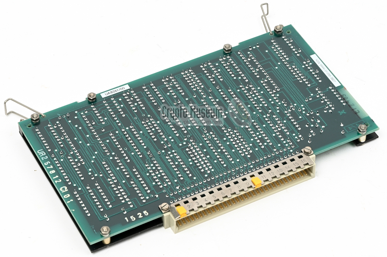
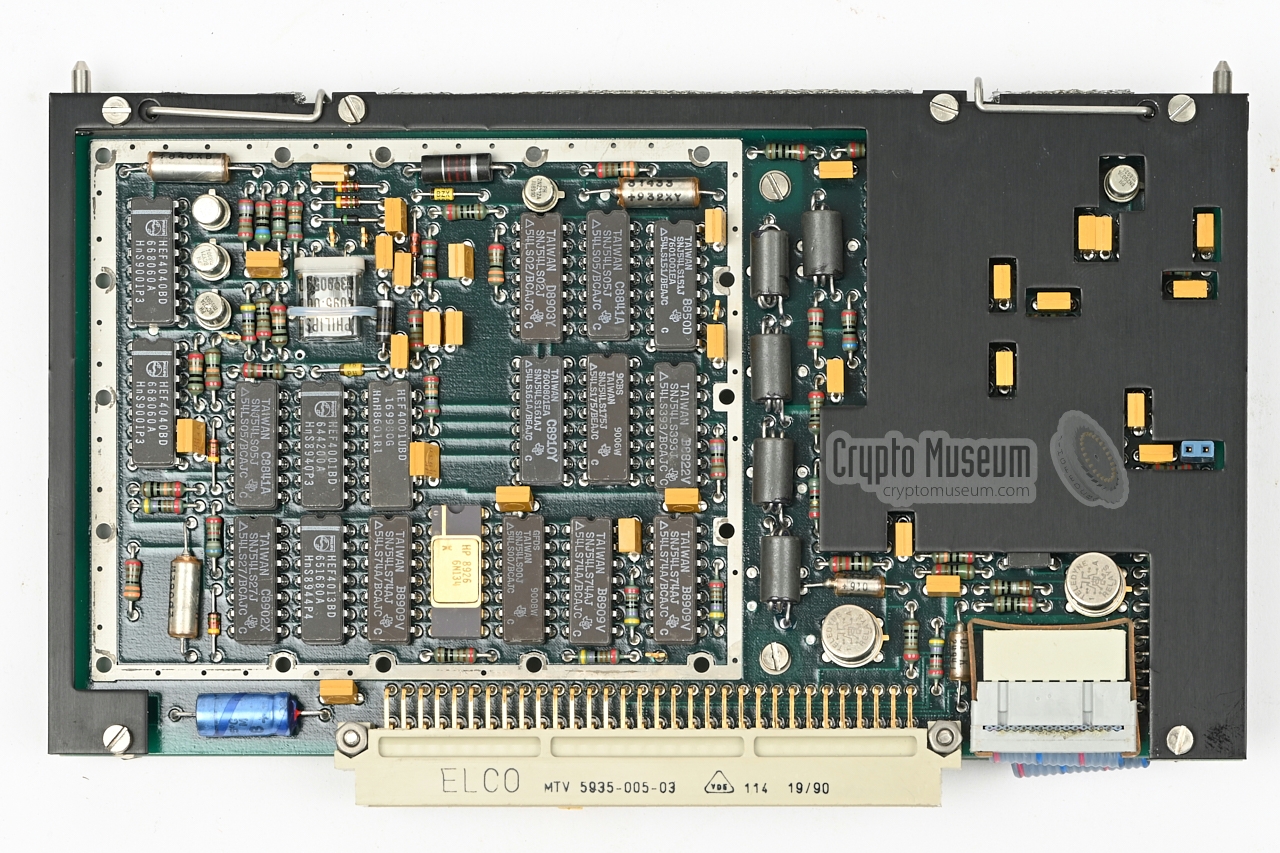
BVO-M is an electronic cipher machine, in which the cryptographic algorithm
is built with non-linear feedback shift-registers (NLFSRs).
As shift-register-based cipher machines were the successors to the
rotor-based cipher machines,
the shift register is often seen as the electronic
equivalent of of an electromechanical rotor. For this reason, the circuit
boards that accomodate the shift registers are called wheels (rotors).
The transmit and receive circuits of the BVO-M, each contain a
key generator that consists of eight such 'wheels', divided over two PCBs.
This means that inside the BVO-M are four identical PCB's, each of which is
the equivalent of four rotors.
Unfortunately, the precise construction of the shift-register-based
key generators is not revealed in the technical manual [C][D].
We hope to be able to present more details about this part of the machine
in due course.
➤ Look inside the BVO-M
|
|
BVO was mostly installed as part of a terminating subsystem on the
DELTACS (ZODIAC) switch.
Each unit was housed in 3U 19" enclosure,
accompanied by a Line Terminating Unit (LTU) and a Universal Junctor (UJ).
It transfers multiplexed data — subscriber and trunk channels —
to/from existing MUCOLEX field units at 1 Mb/s.
An alternative to BVO-M, known as BVO-T, was used for compatibility
with the standard KG-81
Trunk Encryption Device (TED) of the US Army and NATO.
|
The image on the right shows a complete BVO terminating subsystem in a 19"
rackmount. Each subsystem consists of a Line Terminating Unit (LTU) at the left,
a BVO Link Encryptor (LE) at the center, and a Universal Junctor (UJ)
at the right.
The LTU is marked as LA (Dutch: Lijn Aanpassing).
It regenerates a multiplexed data stream at an aggregate bitrate of 256,
512 or 1024 kb/s. It also ensures equalisation for cable lengths up to 2.4 km.
The LTU/LA allows connection to either a
standard telephone line or to a line-of-sight
radio link (LOS), such as the FM-200 transmitter [3].
|
|
|
|
The Universal Junctor (UJ) is marked as UO (Dutch: Universele Omzetter.
It handles the coupling of the matrix subsystem, the control subsystem and the
LTUs. The UJ unit also handles all possible signalling protocols supported by
ZODIAC. It converts the different types of in-band signalling to a uniform
protocol for the information exchange with the control subsystem [3].
|
Below is the simplified block diagram of the BVO-M. The device has a
strict red/black separation, which is implemented as a compartimented
design. At the left is the red interface which connects to the local
(unecrypted) equipment. At the right is the black interface which connects
to the outside world. All lines are differential and asynchronous,
which means that separate data (TXD/RXD) and clock (TXC/RXC) lines are used.
Each line has a separate transformer to make it unbalanced. In addition,
all lines of the red/black compartments are filtered to meet
TEMPEST requirements.
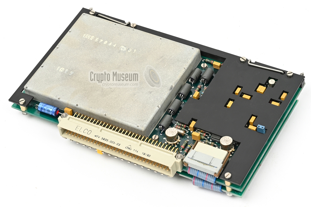
The device has separate transmit (TX) and receive (RX) circuits, each of
which consists of multiple PCBs. At the heart of the TX and RX units
is a key generator, which consists of 8 shift-register-based
virtual 'wheels' (divided over two PCBs) and an ECCM unit.
The latter is responsible for masking any repetitive pulse interferences
which might otherwise be exploited by an adversary.
The device is controlled by a microprocessor (CPU), which controls the
front panel user interface (UI), the transmitter, the receiver and several
types of memory (RAM). Key variables and other operational data is stored
in a special CMOS Static RAM which is retained by a backup battery
installed behind the front panel.
The cryptographic keys can be purged (ZEROIZED) remotely.
|
|
ZODIAC was an integrated tactical communication system, used by the Dutch Armed
Forces from 1979 until the early 2000s. It consisted of a series of fixed and
mobile exchanges (switches) that could be linked together in various ways,
via cables and/or line-of-sight (LOS) radio links.
Each mobile ZODIAC switch was fitted with several BVO-M units,
and in most cases also BVO-T units.
|
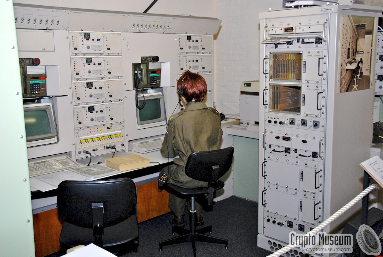
The image on the right shows a typical
ZODIAC automated switch, with sevaral
BVO-M units installed. The image was taken at the
Royal Dutch Signals Museum [2] in July 2008.
It shows a completely functional installation, that was installed in
the museum after the ZODIAC network
was decomissioned in the early 2000s.
Another image of a nearly identical installation is
shown here.
It shows the exchange at an early stage, when it was still called DELTACS [3].
Note that the key-fill sockets are missing from the encryptors,
suggesting that they were dummies.
|
|
|
BVO-M was compatible with a number of international data-standards, including
EUROCOM. This allowed the ZODIAC network to communicate with similar systems
from other countries. For encrypted communication with the US Army and with
other NATO partners, the KG-81 compatible BVO-T was used.
ZODIAC was phased out in the early 2000s, when it was replaced by TITAAN.
➤ More about ZODIAC.
|
When TITAAN was introduced in the early 2000s, the existing
ZODIAC equipment was phased out. BVO-M remained in use however,
and was given a new lease of life by TNO, who designed a new UJ (UO) for it,
shown in the image on the right.
By allowing the BVO-M to
communicate with a modern matrix, existing FM200-based line-of-sight radio
links could be integrated with the new system. TNO called the new interface
TC-FEC (Turbo Code Forward Error Correction).
The upgraded BVO-M units were used until 2007.
➤ More about TITAAN.
|
|
|
|
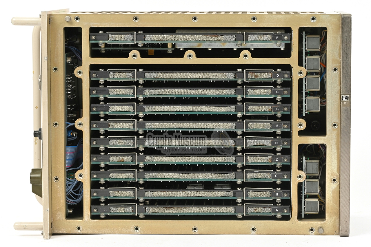
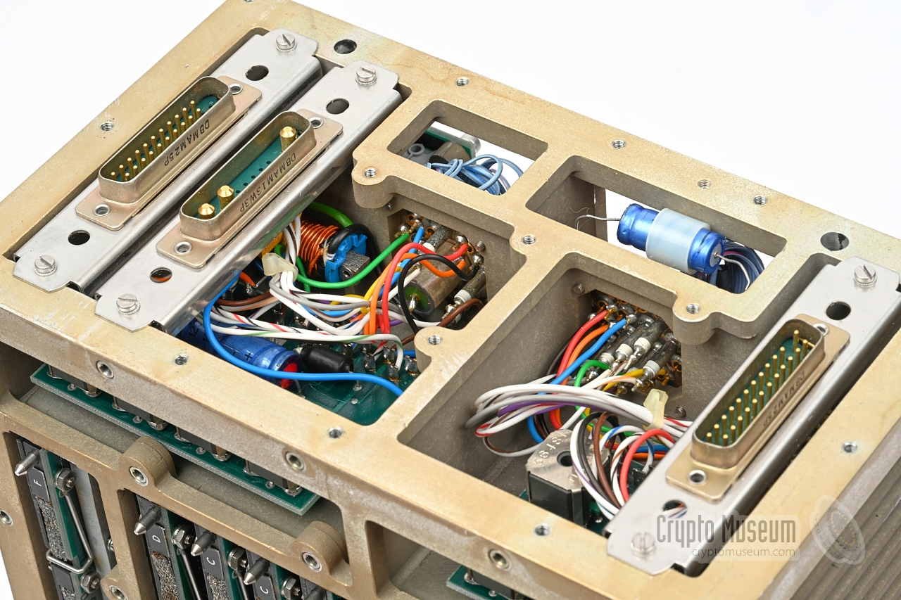
The interior of the BVO-M can be reached from the top, bottom and rear.
by removing the top, bottom and rear panels respectively. The image above
shows the interior after removing the top panel. There are 5 compartments:
front panel, red connection, black connection, black interface and main unit.
Where necessary, the compartments are interconnected via appropriate filtering.
|
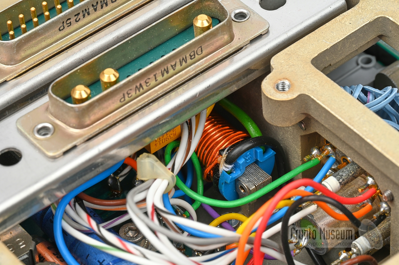
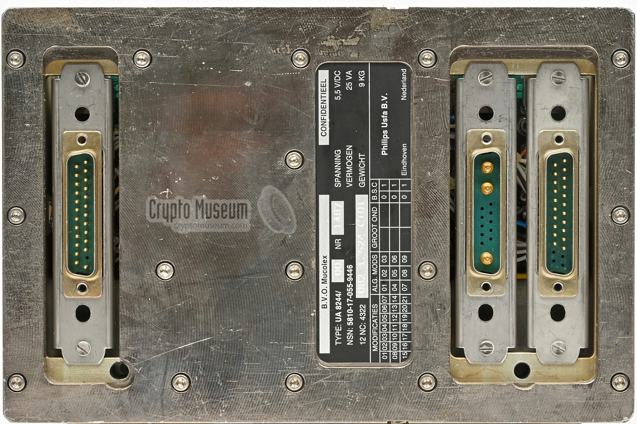
Looking at the unit from the rear, there are three
connectors. From left to right: (1) a DB-25P for connection of the
red 1 signal, (2) a DB-13W3P for connection of the 5.5V power supply, and
(3) a DB-25P for connection of the black 2 signal.
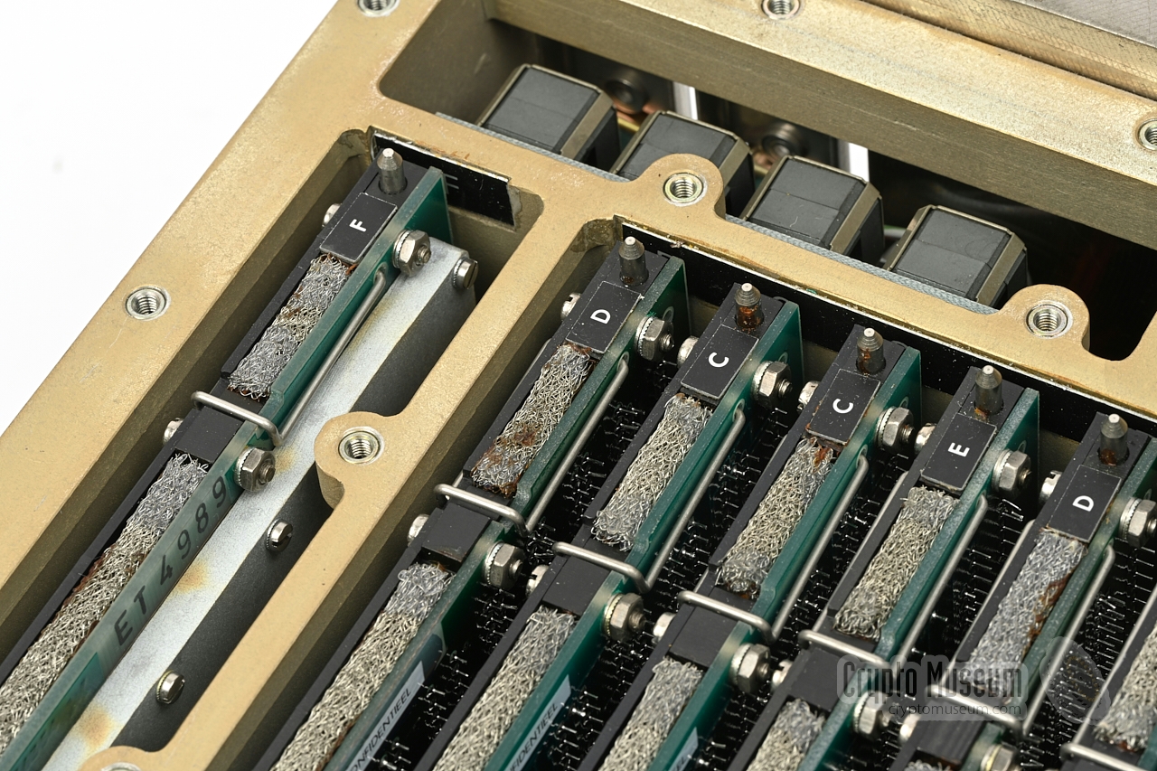
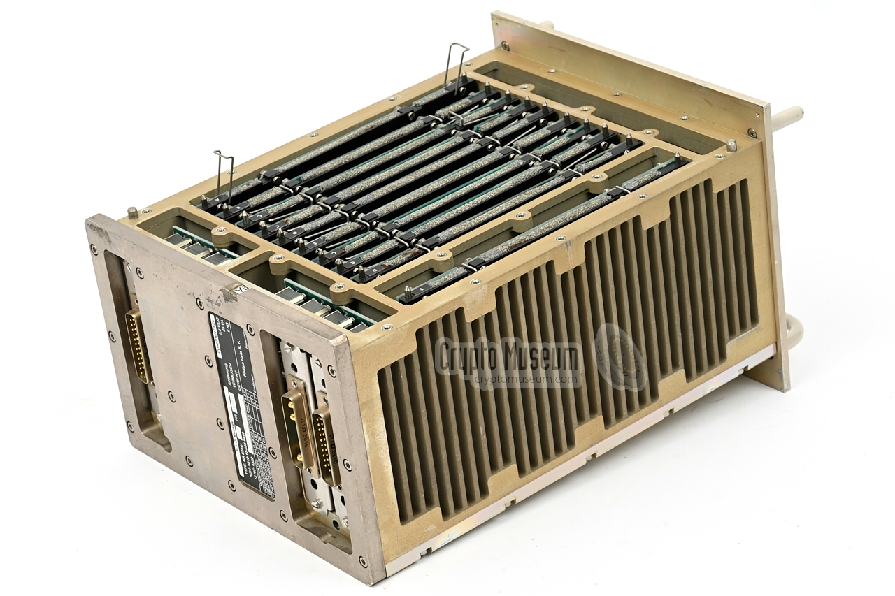
Looking from the top, there are 10 plug-in cards,
interconnected by means of a backplane
that is fitted at the bottom of the
device. Each card is slotted into the backplane by means of a 64-pin DIN
connector. The connectors and the backplane sockets are coded, so that a
particular card cannot be installed in the wrong position.
|
|
|
|
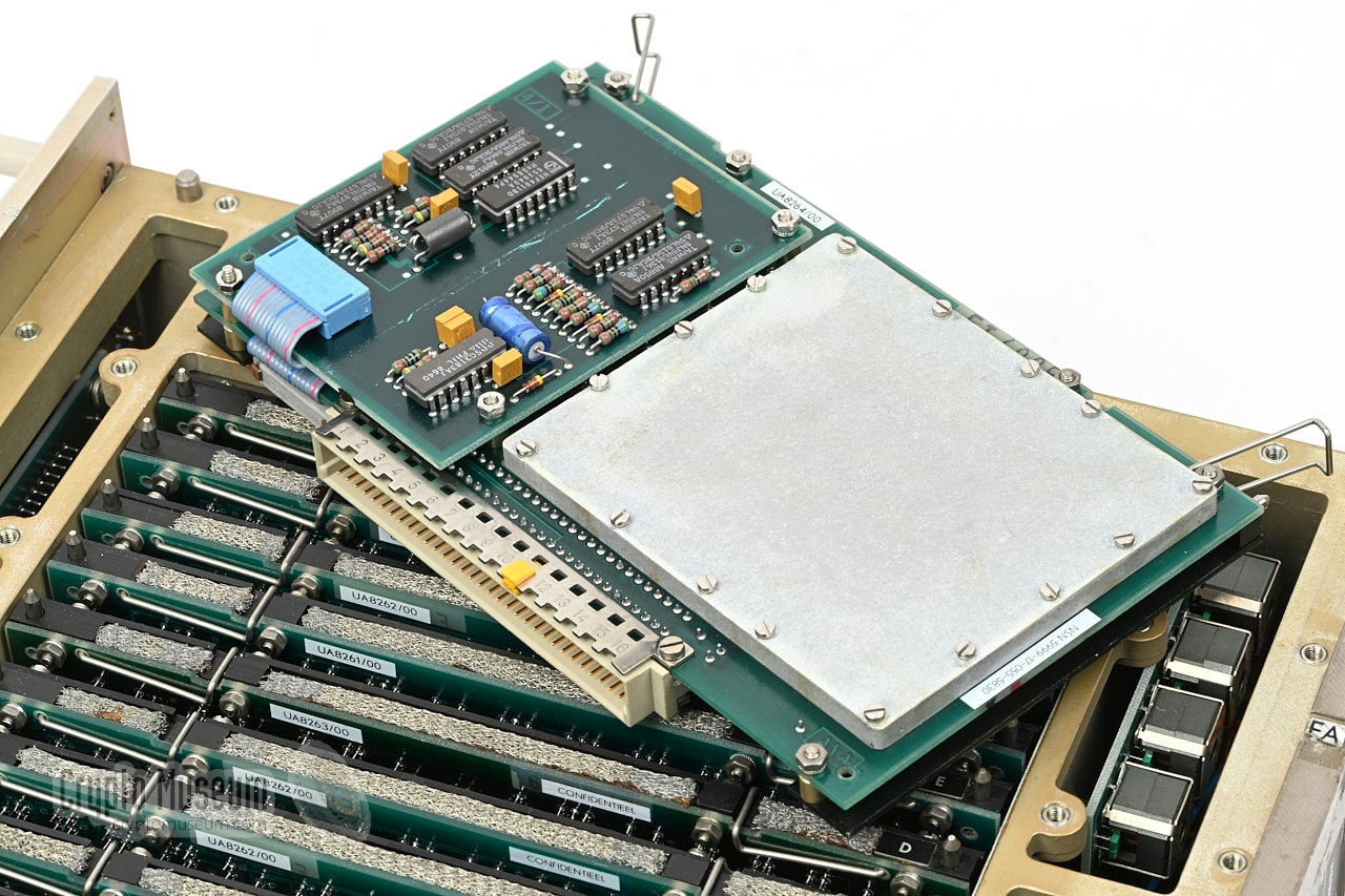
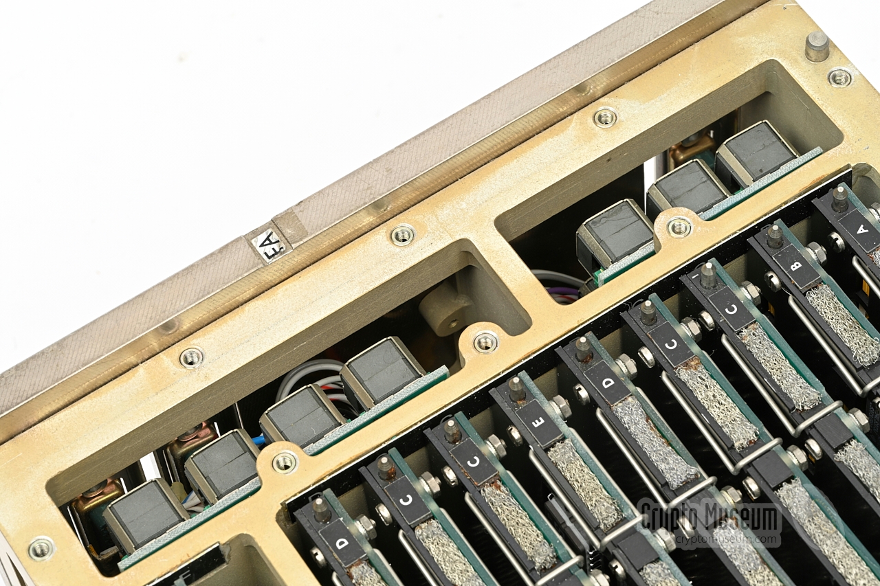
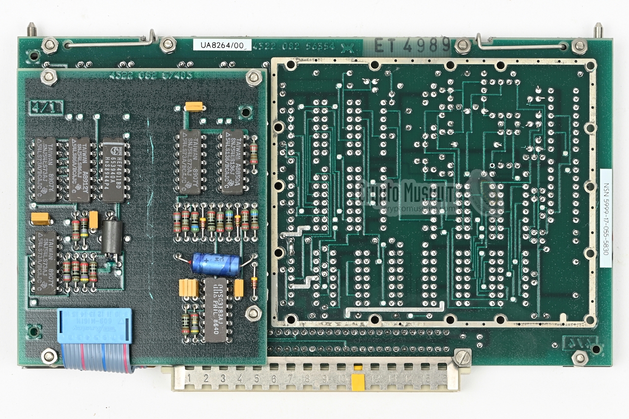
Each plug-in card is identified by a letter (A-F) that is visible towards
the rear end. At the upper edge is a conductive gasket that improves EMC
shielding when the top lid is fitted in place.
In the image above, the black interface (card F)
has been extracted from its shielded compartment.
|
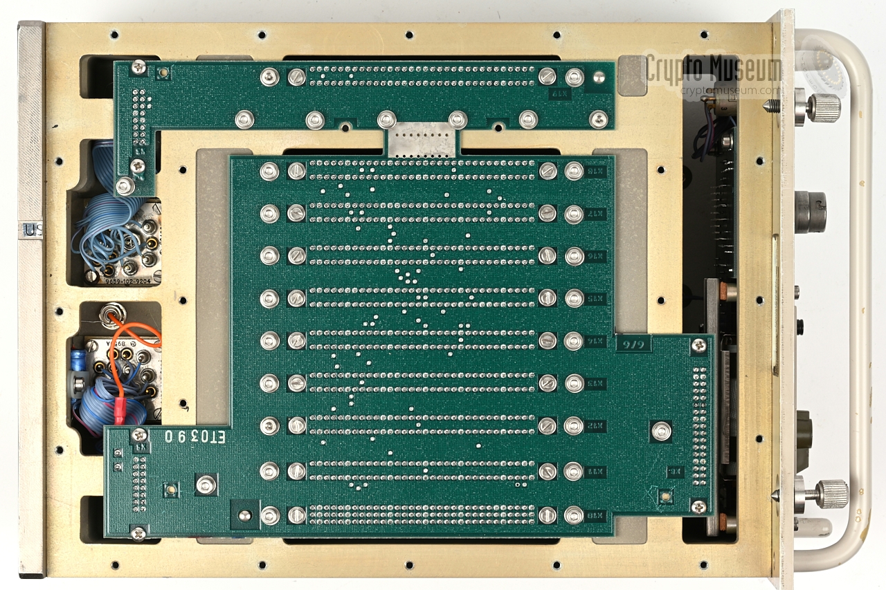
The bottom panel is held in place by 23 hex socket cap bolts. Removing the
bottom panel gives access to the backplane,
part of which is visible in the
image on the right. The backplane
consists of two parts: a 'black' side,
with room for a single plug-in unit (card F), and a 'red' side which connects
all other plug-in circuit boards.
The two backplane parts are interconnected by a small strip at the
centre. Towards the rear of the device, both parts of the backplane
extend to the black and red signal compartments,
where they are filtered
before reaching the connectors.
|
|
|
|
The large part of the backplane
also extends to the front panel compartment,
where it interfaces with the user controls, the indicators and the display.
The remaning compartment can be reached after removing the reinforced
rear panel, which is actually a 10 mm thick stainless steel frame.
|
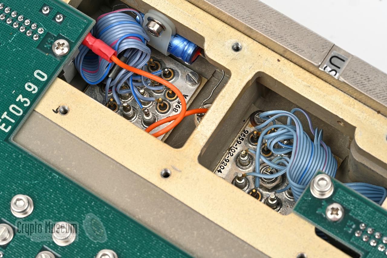
The rear panel is held in place by 10 recessed hex socket cap bolts.
After removing these bolts, the rear panel can be removed without affecting
the connectors, as shown in this image.
There are separate compartment for the red and black signal
connectors. These connectors are wired to two smaller compartments towards the
bottom of the device, via filter blocks that are embedded in the compartment
walls. From there, the wiring is connected to the backplanes of the red and
black interfaces respectively.
|
|
|
|
The wiring from the external power supply unit (PSU), enters the device on
the 3-pin receptacle at the rear. This connector is part of the black
signal compartment. After filtering, the power is passed to the red
compartment, where is additionally filtered and then passed to the
backplane.
|
-
The red interface is for connection of the signal that must be protected.
Note that pin 12 of this connector is missing.
-
The black interface is for connection of the unprotected network. It
interconnects the secured signal with the outside world.
Note that pins 12, 13, 24 and 25 are missing from this connector.
|
|
The red interface — also known as the clear side — is for connection of
the device that must be secured. This is the equipment on which the unencrypted
signal is available.
Below is the pinout of the 25-pin DB-25P receptacle, as seen from the
rear of the device. Note that pin 12 is missing.
|
- L1a
- GND
- L2a
- L3a
- GND
- L4a
- L5a
- GND
- STM bev.
- STM norm.
- Signal ground
- missing
- Remote ZEROIZE
|
- L1b
- L2b
- GND
- L3b
- L4b
- GND
- L5b
- GND
- LA status
- Sync 2
- STM sync
- BATT uit
|
|
|
The black interface — also known as the cpher side — is for connection of
the insecure network. This is the medium over which the encrypted signal is
transmitted.
Below is the pinout of the 25-pin DB-25P receptacle, as seen from the
rear of the device. Pins 12, 13, 24, and 25 are missing.
|
- L1a
- GND
- L2a
- L3a
- GND
- L4a
- BSCa
- GND
- AL-nc
- AL-no
- LAe
- missing
- missing
|
- L1b
- L2B
- GND
- L3b
- L4b
- GND
- BSCb
- GND
- AL-c
- LAc
- missing
- missing
|
|
|
Power should be applied to the 3-pin DB-13W3P receptacle, located to the
left of the black receptacle. Is has three thick pins, marked
A1, A2 and A3. Note that the smaller pins (1-10) are missing from the
receptacle. Below is the pinout as seen from the rear of the device.
|
A1 GND chassis A2 GND 0V A3 +5.5V/DC ± 0.2V
|
|
Device Trunk encryption device Purpose Secure military bulk data transmission Model BVO-M Designator UA-8244 NL/Army KY-6127/M NSN 5810-17-055-9446 12NC 4322 082 12624 Years 1981-2007 Manufacturer Philips Usfa BV Network ZODIAC, TITAAN User Royal Dutch Army Encryption Proprietary (Mucolex) Key length 128 bits (including 8-bit checksum) Plug-in cards 10 (see below) FILL STANAG 5063, DS-102 (e.g. KYK-13, KOI-18, etc.) Speed 2 Mb/s Power 5.5V/DC ± 0.2V EMC MIL-STD-461 TEMPEST AMSG 720A Environment DEF STAN 07 55 Temperature -25°C to +55°C (storage -40°C to +70°C) Humidity ≤95% Dimensions 300 × 200 × 150 mm Weight 8.5 kg
|
- Eurocom D/1, paragraph 1B6, interconnection point B
- Black Station Clock (BSC), when available
- Alarm relay for external alarm indicator
|
- Eurocom D/1, paragraph 1B6, interconnection point A
- Indicators for status of security, synchronisation and operation
- Remote ZEROIZE of crypto variables
|
- Red interface
- Processing unit
- 4 × Key generator 1 (4 'wheels' per board)
- 2 × Key generator 2
- Pattern unit
- Black interface
|
LTU Line Terminal Unit (Dutch: Lijn-Aanpassingseenheid) PSU Power supply unit DMD Digital Multiplexer/Demultiplexer
|
|
The BVO-M is known under the following names and designators:
|
- BVO-M
- BVO-Mucolex
- Mucolex II
- UA-8244
- KY-6127/M
- NSN 4810-17-055-9446
- 12NC 4322 082 12624
- Dacolex
- UA-8257
|
- Philips Usfa, BVO-M stock photographs
Crypto Museum Photo Archive #300633.
- Royal Dutch Signals Museum
Visited 2008.
- AJW van Daal & P van der Vlist, DELTACS - a versatile tactical communication system
Philips Telecommunicatie Industrie BV (PTI), Hilversum (Netherlands), 1984.
Reprint from Philips Telecommunication Review, Vol. 42, No. 2, pages 74-89.
- Th. Sierksma & A. Bijlsma, Transmissie binnen TITAAN
Intercom, 2005, Volume 1, p. 41-45. Dutch.
|
|
|
|
Any links shown in red are currently unavailable.
If you like the information on this website, why not make a donation?
© Crypto Museum. Created: Friday 14 December 2012. Last changed: Wednesday, 05 November 2025 - 11:51 CET.
|
 |

|
|
|


![Complete terminating subsystem. Photo courtesy Philips Usfa [1]](img/300633/000/full.jpg)