|
|
|
|
|

|
|
Covert Recorders Nagra Nagra SN →
Nagra SNST playback unit
DSP-1 is a playback unit for the covert
Nagra SNST miniature stereo tape recorder,
introduced in 1977 by Nagra in Cheseaux-sur-Lausanne
(Switzerland). The device contains a sound-expander that matches the
sound-compressor of the SNST, plus a stereo amplifier with built-in
speaker. The DSP-1 is also suitable for the covert
Nagra SN tape recorder —
the mono version of the SNST.
|
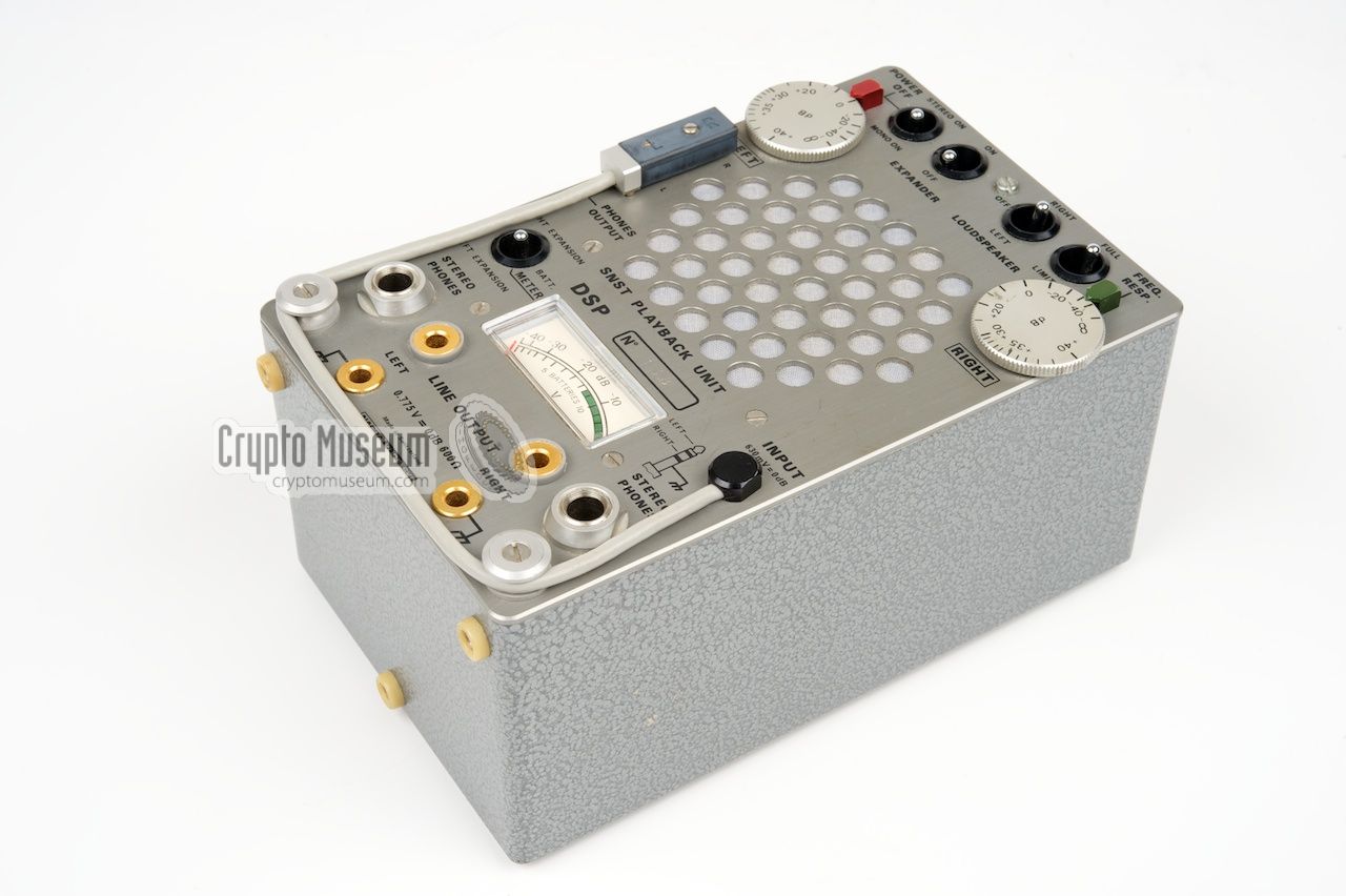
The DSP-1 is housed in a hamerite grey metal enclosure with an eloxed
aluminium front panel. It measures 10 x 8 x 15 cm and weight xxx grams
(without batteries).
It is powered by eight 1.5V AA-size batteries
(12V) that are installed behind a transparent panel at the rear side.
All controls and connections are at the front of the device, together with
the speaker and the meter. The DSP-1 has a fixed-length audio cable for
connection to the Nagra SNST recorder. It has a double 3 mm jack at the end
(for two channels) which can be
stored to the left of the speaker.
|
|
|
|
When connecting the Nagra SNST, the double jack should be
removed from the storage socket
and inserted into the SNST. When using the DSP-1 in combination
with the mono variant (SN), only one of the two pins
of the double jack is used.
The device contains a sound-expander that converts the compressed sound
from the SNST back to its original dynamic range. For use with devices
that do not have a compressor (such as the Nagra SN),
the expander can be disabled.
|
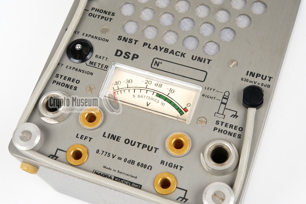
The image below shows the front panel of the DSP-1, which holds all controls
and connections. At the centre of the unit is a rather large loudspeaker that
produces a clear and crisp sound. At the
upper edge of the case are four selector
switches. The leftmost one is the ON/OFF switch. It is also used to select
between mono and stereo playback. The second switch is used to turn the
audio expander on or off. The other two switches are for the loudspeaker and
the low-pass filter. The audio level (volume) is controlled by two large knobs
(left/right) at either side of the speaker.
Most of the connections are located at the
lower part of the front panel. There
are two stereo headphone sockets that accept a 6 mm jack, plus a set of
banana-type sockets at which the audio is available at line level. The function
of the meter can be determined by a switch to its left.
It can be used to check the battery voltage, or the audio expansion of each
channel (left/right).
The audio input (from the Nagra SN) is located to the right of the meter.
It consists of a short fixed cable with a two-pin rectanglular connector at the
end. When not in use, the cable runs past two circular guides at the lower
corners of the case, and the connector is
stored in a socket to the left of the
speaker. It has to be removed
when connecting the DSP-1 to the Nagra SN/SNST.
When the unit is in use, the empty storage socket can be used for connecting
a pair of earphones.
|
|
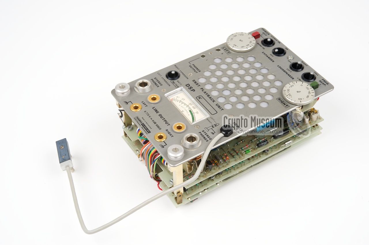
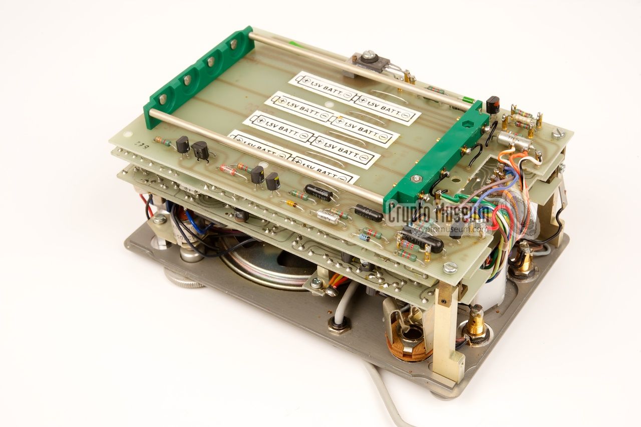
The interior of the DSP-1 can be accessed by removing one bolt from the top
of the unit and two of the rubber feet from the bottom. This allows the front
panel to be removed from the case.
The DSP-1 consists of three Printed Circuit Boards (PCBs)
that are mounted to the front panel.
|
The image on the right shows the interior after it has been removed from the
case. All controls, the speaker and the meter are
mounted to the rear of the front panel
by means of metal stubs.
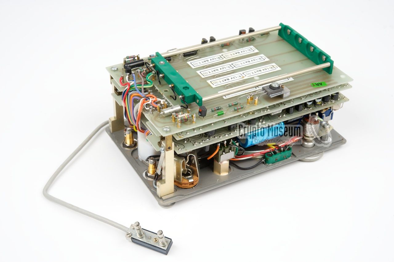
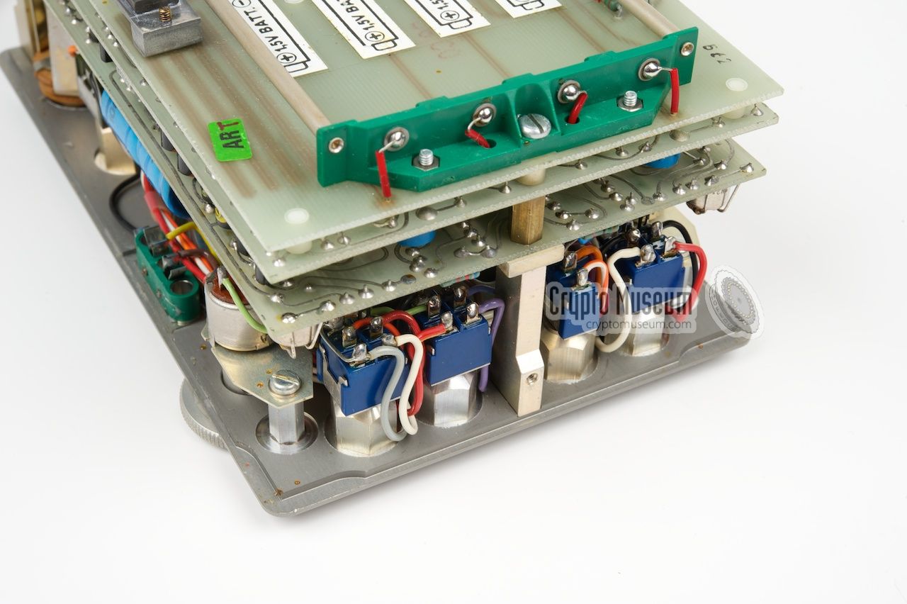
The three PCBs are mounted together as a 'sandwich' of which the
bottom board contains the
purpose-built battery holder.
The remaining two boards hold the electronic circuits.
All wiring of the boards is at one side,
so that they can be separated easily
in case of service or repair.
|
|
|
|
|
|
Any links shown in red are currently unavailable.
If you like the information on this website, why not make a donation?
© Crypto Museum. Created: Monday 06 October 2014. Last changed: Wednesday, 20 October 2021 - 07:24 CET.
|
 |

|
|
|