|
|
|
|
|

|
|
Germany France Cold War Telefunken ESK-632 → ← B2M
German/French spy radio set
ESK-52 is a spy radio set, developed in 1952
by Telefunken
in Hannover (Germany) for clandestine operations of the French
intelligence services. The radio was based on the similar Type 41,
which was built for the German intelligence service, the
Bundesnachrichtendienst (BND).
Like the Type 41, it is actually a post-war replica of the
British Type 3 Mk II (B2).
For security reasons the ESK-52 was designated 1 Amateurgerät
(Amateur Device) in the original service documentation.
|
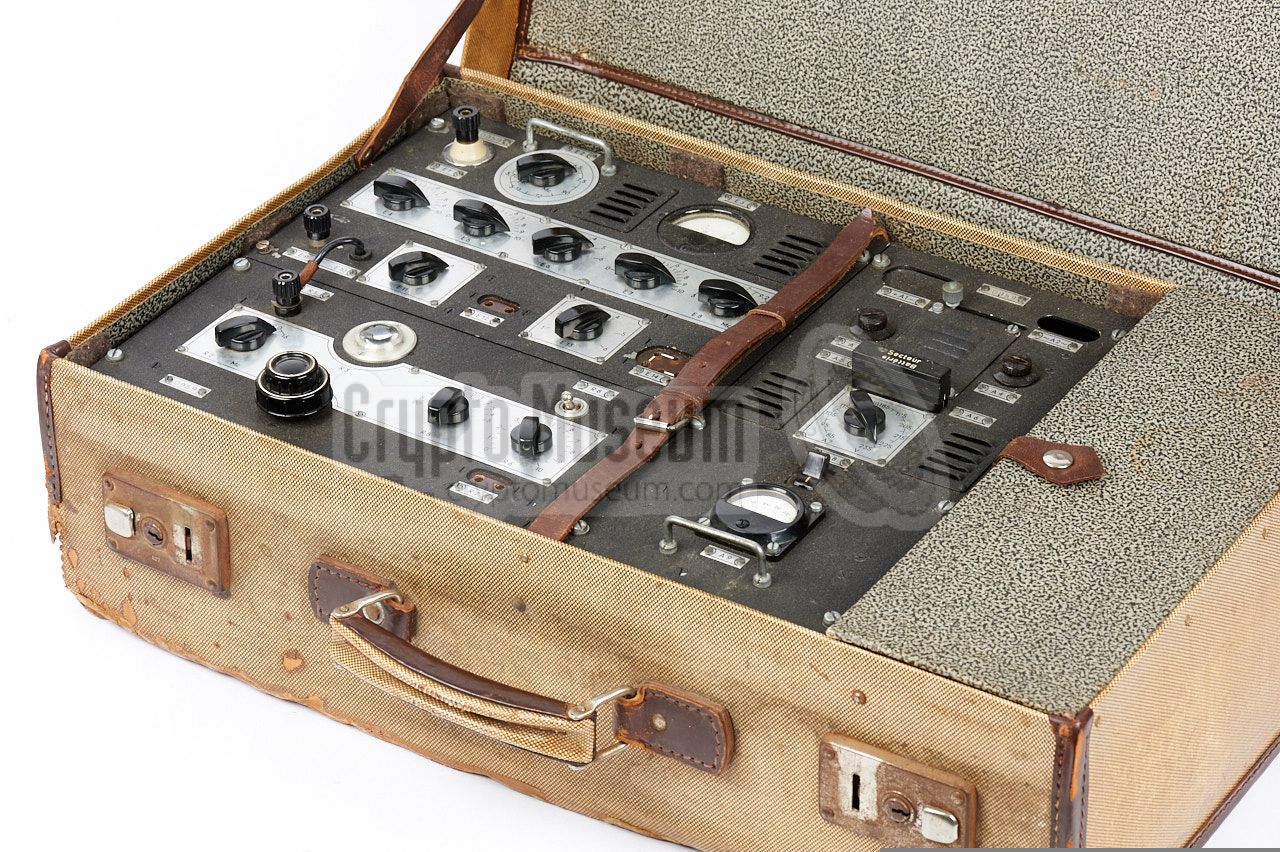
The radio set is housed inside a large cardboard suitcase and
consists of three units, just like the British B2: a
power supply unit (PSU)
at the right, a receiver (RX)
at the front, and a transmitter (TX) at the back.
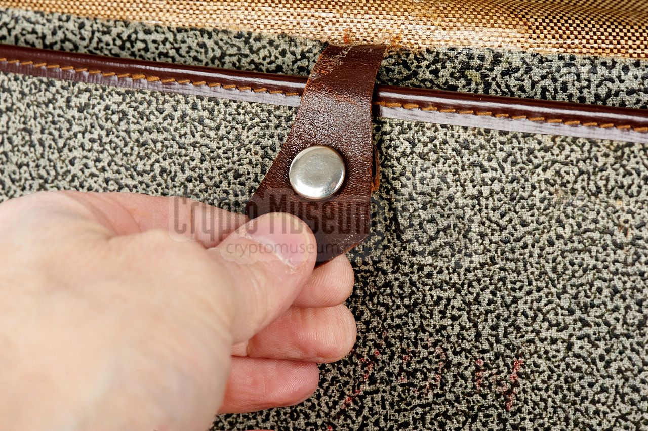
A leather strap at the center keeps the set in place when travelling around.
At the far right is a large storage compartment in which the
acessories,
such as the morse key,
the headphones, the power cables, the antenna
and spare valves are kept. The documentation (operators manual,
frequency tables, etc.) are stowed
behind a panel in the top lid
of the case.
|
|
|
The ESK-52 shown here has a control panel that is labelled in French.
During the Cold War, it was used for many years
by the French intelligence service SDECE.
Although the radios officially had to be destroyed once they were
decommissioned, some have miraculously escaped demolition.
It is currently unknown how many ESK-52 sets were produced, but given
the low serial number of our set (0059) it is likely that no more than
200 sets were produced. Today they are very rare.
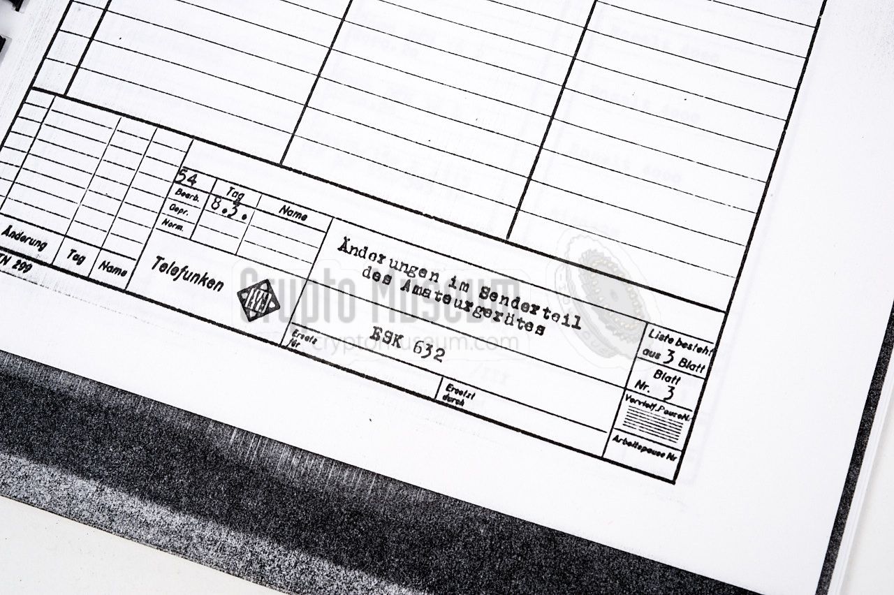
A few years after the launch of the ESK-52 – in 1954 –
Telefunken introduced the
ESK-632 which was an improved version of
the ESK-52. A modulation amplifier was added to the transmitter
and a socket for a microphone was added to the front panel.
It was also listed as 'Amateur Device'.
|
-
It is possible that the prefix 'ESK' is the abbreviation of Empfänger-Sender Kombination
(receiver-transmitter combination, or transceiver), but this is by no means certain.
|
The image below provides an overview of the controls and connections
of the ESK-52 (Type 41). The device is housed in a sturdy cardboard suitcase
of the era, allowing it to be carried around unobtrusively. Like the British
Type 3 Mark II (B2), the actual transceiver consists of three units:
transmitter, receiver and power supply unit (PSU). Unlike with the B2 however,
the three units of the ESK-52 are mounted in a single metal frame,
kept in place by a leather strap at the centre.
All controls and connections are labelled in French. The text is not engraved
into the front panel, but is screen-printed on removable aluminium plates that
are held in place with screws. This allowed the manufacturer to support
alternative languages and countries. Rather than text (e.g. 'Crystal'), most
labels carry a reference number such as 'E14', which stands for Emmiteur
(transmitter), index 14. It corresponds with the text in the
operating instructions [A].
|
Shortly after WWII, in 1950,
Telefunken
in Hannover (Germany)
started building spy radio sets that were inspired by
the British WWII Type 3 Mark II (B2).
The first radio set that was produced by the HOGA 1 business unit
at Telefunken was the B2M,
which was actually a 'chinese' copy of the British B2.
The front panel layout and the circuit diagram were nearly identical
and the only real difference was the use of 'rimlock' type valves in
the oscillator circuits of the German B2M [1]. Unlike the original
B2, the B2M consisted of three units in a single
metal enclosure.
➤ More about the B2M
In 1952, the ESK-52
and the Type 41 were introduced at the successors
to the B2M.
The design is based on the B2M, but contains a number of
improvements, such as the absence of plug-in coils in the transmitter
section. Although the ESK-52 consists of 3 units (RX, TX and PSU),
they are mounted together in a single frame
(and wired internally) that is built inside the suitcase.
As the transmitter of the ESK-52 can only be used for CW
(morse),
an improved version, known as the ESK-632
was released in 1954. A modulation amplifier was added to the transmitter,
allowing the connection of a crystal microphone in order to produce
Amplitude Modulation (AM).
➤ More about the ESK-632
|
 |
-
At the time, the HOGA business unit of Telefunken Werk-Hannover,
was responsible for the production of the ESK-52 radio set and the
earlier B2M. HOGA is the abbreviation of
Hochfrequenzgeräte und -anlagen (High Frequency Devices and Systems).
|
The transmitter is built around two American valves (tubes):
a 6AG7 for the crystal-based oscillator (CO) and a 6L6 for the RF
power amplifier (PA). It covers a frequency range of 3 to 16 MHz
and produces an output power of 20W.
The transmitter is suitable for CW only.
|
|
|
|
The superheterodyne receiver is built around four valves:
2 x ECH42 and 2 x EAF42. It has the same frequency span as the
transmitter (3 to 16 MHz), divided over three ranges
(3-5.5, 5.5-7 and 7-16 MHz). The IF frequency is at 470 kHz.
|
|
|
The Power Supply Unit (PSU) is mounted to the right of the transmitter
and receiver and is internally wired to the other two units.
It is suitable for a wide range of AC mains voltages (90 - 230V),
but can also be operated by a 6V DC battery. In the latter case
an electromechanical vibrator is used to convert the 6V DC into
the LT and HT voltages needed by the set.
|
|
|
|
The ESK-52 was usually supplied with a good quality morse key
such as the bakelite Wehrmacht key shown here, which was actually
a leftover from WWII. Note the special connector with the narrow
pitch that is used for connection to the transmitter.
|
|
|
|
The ESK-52 is suitable for connection of any high-impedance
pair of headphones. It was commonly supplied with the Telefunken
headphones shown here, which was actually a leftover from WWII.
|
|
|
The suitcase has a large storage compartment to the right of the radio
set, in which accessories like morse key, headphones, power cables and
antenna wires were stowed.
Also in this compartment are the spare valves (tubes), fuses, a mains lamp
adapter, etc.
|
|
|
The ESK-52 was supplied with typed instruction in French.
For service personnel, there was also a technical manual with circuit
descriptions and circuit diagrams. In the latter manual, the radio was
identified as Amateurgerät (amateur device) in order to hide its true purpose.
The documentation was stowed inside the
rear compartment,
inside the top lid of the suitcase.
➤ Short form instructions
|
|
|
In an operational context, the ESK-52 was supplied with a frequency table
that was used by the operator to determine which channel to use on certain
days and times. The image on the right shows an original frequency table that
was found with the radio set featured here.
Several blank frequency tables were provided for 'future use' by the operator.
The tables were supplied in a transparent plastic 1 sleeve.
➤ Original frequency table
|
|
|
-
The plastic sheet has been removed from
the tables shown here, as it contains acetate which produces toxic
fumes that can potentially damage the documents.
|
Device Suitcase spy rado set Purpose Agent communication Model ESK-52, Type 41 Year 1952 Manufacturer Telefunken, Hannover (Germany) User French intelligence, French stay behind Predecessor B2M Successor ESK-632 Mains 85 - 234 V AC, 40-60 Hz Battery 6V DC Vibrator NSF 32 - 2 NT 6 Parts 3 (transmitter, receiver, PSU) Dimensions 585 × 350 × 170 mm (suitcase)
430 × 320 × 150 mm (bare radio set) Quantity 200 (est.)
|
Frequency 1.4 - 9 MHz (1.4 - 4.5 MHz with doubler) Output 20W (15W when battery powered) Modulation CW Impedance 600 - 1000 Ω Valves 6AG7, 6L6G
|
Frequency 1.4 - 9 MHz Bands 3 (1: 1.6-3 MHz, 2: 3-5.5 MHz, 3: 5.5-9 MHz) Modulation CW, AM Sensitivity < 1µV (A1, without filter)
< 2µV (A1, with filter)
< 5µV (A3) Valves 2 × ECH42, 2× ECF42
|
- Antenna wire (20 m)
- Ground wire (10 m)
- 2 × Isolator
- Ground pin
- Morse key
- Headphones
- Battery power cable
- Mains power cable
- E10 light fitting adapter
- Spare fuses
- Spare valves (tubes)
- Operating instructions
|
- Type 41
- ESK-52
- Poste valise Téléfunken
- Amateurgerät
|
0059 All Crypto Museum, Netherlands 0127 Military Wireless Museum, UK 0140 Military Wireless Museum, UK 0163 Military Wireless Museum, UK
|
-
Poor quality copy.
-
The extra circuit (AM voice modulator) of the ESK-632
is embedded within this manual (page 23-26).
|
|
|
|
Any links shown in red are currently unavailable.
If you like the information on this website, why not make a donation?
© Crypto Museum. Created: Sunday 05 February 2017. Last changed: Tuesday, 20 August 2024 - 15:56 CET.
|
|

|
|
|