|
|
|
|
|

|
|
Austria Cold War SBO BE-20/2 → ← BE-20
Austria spy radio set
- this page is a stub
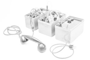
BE-20 was a three-piece short-wave
spy radio set,
built around 1948 by Dr. Hermann Berger
in Innsbruck (Tirol, Austria). The device was intended for several customers,
including the Austrian Army, the armies of the occupying forces 1
and the state security services.
It was also used for a secret
Austrian Stay-Behind network
that would be activated
in case of problems with the USSR.
|
The BE-20/1 is the protype of the radio set, that was presented to the French
Army around 1948. After a few modifications, the set was approved and
went into production as the BE-20/2 (Poste Cunzi) for the French Army,
and BE-20/3 for all other customers, such as the
B-Gendarmerie and the
secret stay-behind organisation ÖWSGV.
Although the circuit diagrams of the BE-20/1 prototype have been retrieved
(see below), there are no surviving samples of the device that we are
aware of. The circuits are very similar to the actually released devices
BE-20/2
and BE-20/3.
|
|
|
Note however that the pinouts of the various connectors and sockets on
the body of the device are completely different from the ones on the
released devices. The circuit diagrams below are provided for
reference only. Please use the information with care when restoring
a device.
➤ Other versions of the BE-20
|
-
Shortly after WWII, Austria was occupied by the United States, the Soviet
Union, the United Kingdom and France. It became fully independent again
on 12 May 1955. ➤ Wikipedia
|
Power 95 - 220V AC, generator 6 - 45V, 6V or 12V DC with inverter
|
Frequency 3 - 5.6 MHz, 5.6 - 9 MHz Sensitivity 2µV (phone), 1µV (CW)
|
Modulation Phone (A3), Telegraphy (A1, CW) Frequency 3 - 9 MHz (crystal) Output 6 Watt (phone), 18 Watt (CW)
|
-
Note that this circuit diagram is for the BE-20/1 prototype and does
not fully match the circuit of the production units (BE-20/2). Ignore the
connections of the 6-pin LIST connectors as they are wrong.
Documents kindly supplied by Günter Hütter [3].
|
|
|
|
Any links shown in red are currently unavailable.
If you like the information on this website, why not make a donation?
© Crypto Museum. Created: Monday 19 December 2016. Last changed: Thursday, 15 December 2022 - 17:04 CET.
|
 |

|
|
|