|
|
|
|
|

|
|
Austria France Cold War SBO BE-20/3 → ← BE-20/1
The radio set consists of three equally sized metal enclosures: a
power supply unit (PSU),
a transmitter (TX)
and a receiver (RX).
The units are connected together with thick red 2 cables,
with the transmitter acting as the central hub.
The image on the right shows a typical Berger BE-20/2 setup with (from left
to right) receiver,
transmitter
and PSU. The PSU is connected to
the AC mains and has two voltage selectors (plugs) to set the
appropriate voltage. An American field telephone
handset TS-13-F 3
with Y-cable is connected to the transmitter and to the receiver.
|
|
|
Development of the BE-20 took place in the late 1940s. In 1948 the first
prototype, the BE-20/1, was supplied to the
French Army for evaluation.
This resulted in an order for 100 complete sets, that were codenamed
Poste CUNZI, after the name of Berger's contact person in the French Army
[5].
The production version was
designated BE-20/2 and was largely built from wartime (German) surplus parts,
complemented by components from Berger's own factory.
The 100 units were built between 1949 and 1952 [1].
A grey variant, with a front panel in German, is known as BE-20/3.
The sets were used a part of a nation-wide communications network for the
secret underground Austrian stay-behind organisation
that would have been activated in case of problems with the
Soviet occupation forces.
Although the French Army
had ordered and payed for the 100 units,
the last production batch of 10 units was never taken, probably because
they had enough, or because other radio sets had meanwhile become available
to them.
The 10 surplus radios were left to the Austrian
B-Gendarmerie 4 (now: Bundesheer)
at the Conrad Kaserne in Innsbruck,
where they were used for sending weather reports, and later
(with permission) by Radio Amateurs (HAMs).
➤ Other versions of the BE-20
|
 |
-
French Indochina was a group of French colonial territories in South-East
Asia. After WWII, several of the former colonies declared their independence
and finally, following the Geneva Accord of 1954, the French evacuated and
French Indochina was dissolved [4].
-
Apart from red, some units had grey or black cables, indicating that
Berger used whatever parts he could get his hands on when manufacturing
these radio sets.
-
The Berger BE-20/2 should be used with the American TS-13-F handset,
which has a carbon microphone. Note that the prototype radio BE-20/1
can only be used with the TS-13-E version of
the handset. More...
-
The B-Gendarmerie was the predecessor of the Austrian Federal Army
(Österreichisches Bundesheer), which was similar to the German post-war
Bundesgrenzschutz (BGS).
➤ Wikipedia
|
The diagram below shows a complete BE-20/2 (Cunzi) radio station with
all cables in place. At the far right is the power supply unit (PSU) that is
connected to the AC mains. It is connected to the transmitter via two thick
red cables and is only activated when both cables are inserted.
The radio station was intended for voice transmissions (speech) in AM,
but for emergency purposes it was possible to fall back to CW and use
morse code for sending messages. For this
reason a fixed built-in morse key has been embedded with the transmitter.
Unfortunately, there is no connection for an external morse key,
which was considered a disadvantage by some users.
|
The PSU is the heaviest part of the three-piece radio set, mainly because
it houses a large AC transformer with many taps, allowing it to be used
on a wide variety of AC mains voltages, between 95 and 235 V. The desired voltage
is selected with two plug-in power caroussels.
The PSU is connected to the transmitter via two thick red cables: one running
from the PSU to the transmitter and the other one running from the transmitter
to the PSU. Both cables have to be in place before the PSU is enabled.
|
|
|
The transmitter acts as the central hub of the radio set and has three
fixed wires for connection to the PSU and the receiver. The transmitter is
crystal-operated and is suitable for the entire 3 - 9 MHz frequency range.
Power is supplied by the PSU via two thick red cables each with a 6-pin LIST
plug at the end: one from the PSU to the transmitter, and one from the
transmitter to the PSU. An external wire antenna should be connected to the
socket marked A at the top left. A short orange wire distributes
the antenna signal to the receiver.
|
|
|
The receiver has a Variable Frequency Oscillator (VFO) and can be adjusted
freely over the entire 3 - 9 MHz frequency range, divided over two bands
that span 3 - 5.6 MHz and 5.6 - 9 MHz respectively. It has a sensitivity of
1µV in CW (morse) and 2µV in AM (phone).
Power is supplied by the transmitter via a 6-pin LIST plug. The antenna signal
is also shared with the transmitter and is supplied via an orange rubber
antenna wire that is fixed to the body of the transmitter.
Audio output is delevered to a 6.3 mm jack socket.
|
|
|
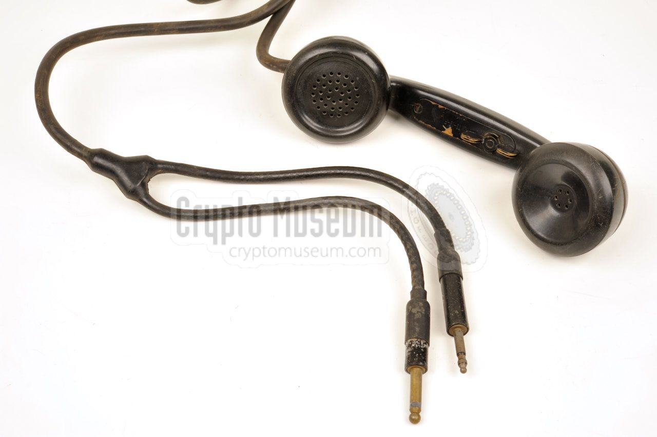
For speech (phone), a TS-13-F handset was used, as built
by the American Microphone Company.
It has a carbon microphone and was also used with some popular WWII equipment.
The handset has a Y-shaped cable with a PL55 and a PL68 plug at the ends.
A butterfly-type PTT switch in present on the inside of the grip.
Note that the prototype BE-20/1 only works with the E-version of this
handset, as it is the only one that has a 11315-A dynamic 1 microphone.
|
|
|
-
The TS-13-E is also used with the BC-1000 radio and the EE-8B field phone.
All other versions of the handset have a carbon microphone and are
suitable for the BE-20/2 production variant.
|
In order to protect the units agains dust and moist, some radio sets were
supplied with bulged metal covers that could be fitted over the front panels.
The covers could be fastened with a canvas strap.
The image on the right shows two covers, one for the PSU (Al) and one for
the transmitter (E) as they were found with a surviving BE-20/2 [3].
|
|
|
|
CUNZI is housed in three aluminium enclosures: two
equally sized boxes are used for the PSU and the transmitter, whilst the
receiver is housed in a somewhat smaller case. The interior of each unit
can be accessed easily by removing just one screw at the rear and taking
off the case shell.
|
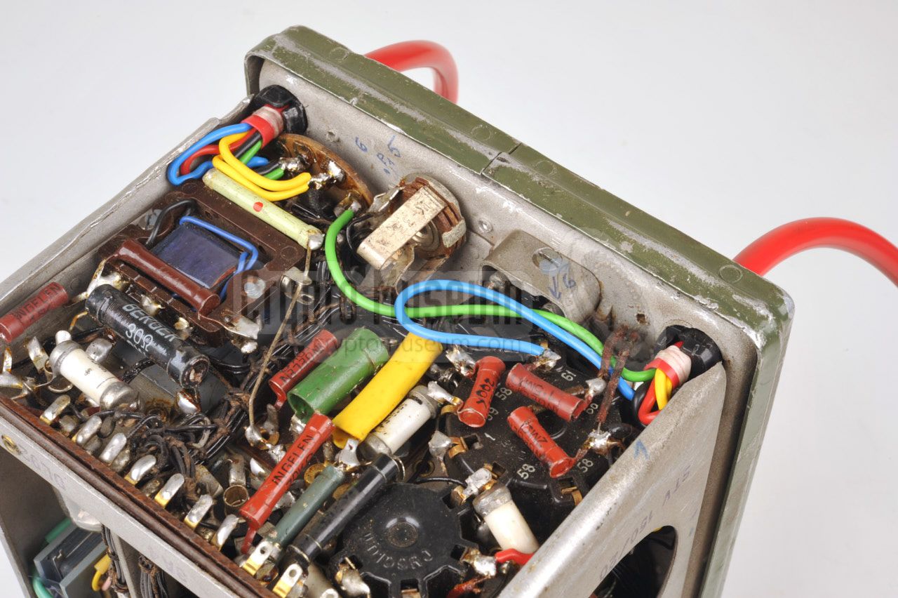
In all three units, the components are mounted to the front panel so that
no cables or plugs have to be removed. The set is extremely well designed
and built, and should be considered very small for the era
in which it was conceived.
Repairing a broken set however, is very difficult, as most components
can not be accessed easily without completely dissassembling the unit.
The image on the right shows the dense interior of the transmitter,
with the PA valve at the bottom. In order to provide sufficient cooling,
ventilation holes are present at the top of the transmitter.
|
|
|
For a more detailed description of the interior of the three units,
please refer to out page about the BE-20/3,
which is nearly identical.
➤ Interior of the BE-20/3
|
|
Bringing an old Berger BE-20/2 CUNZI back to life may not be straightforward,
as some of its components may have aged, and the thick power cables are very
likely to have become brittle over time, as they consist of rubber wires.
They have to be replaced before turning the radio on.
|
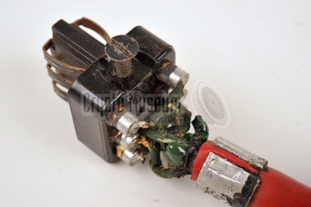
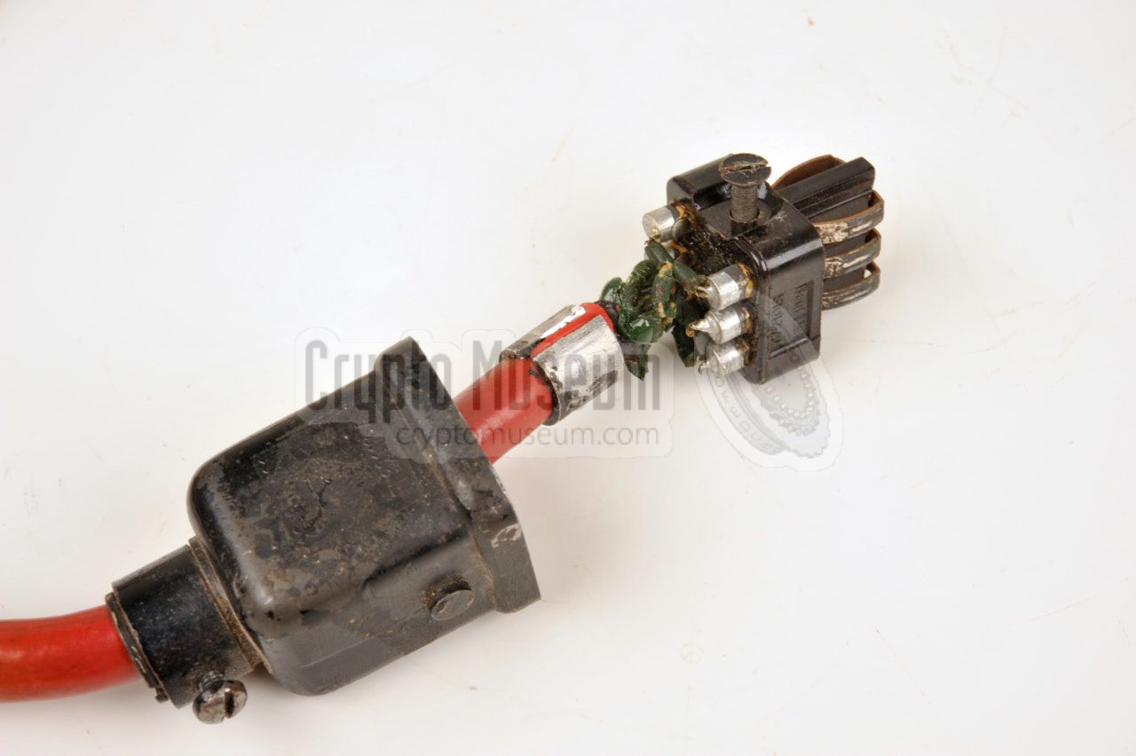
Depending on the type of cable used for interconnection between the three
units, the cable may have become stiff over time. Furthermore, as the internal
wires of the cable are made of rubber, they may have decomposed completely,
as illustrated in the image on the right. Such cables are beyond repair and
must be replaced.
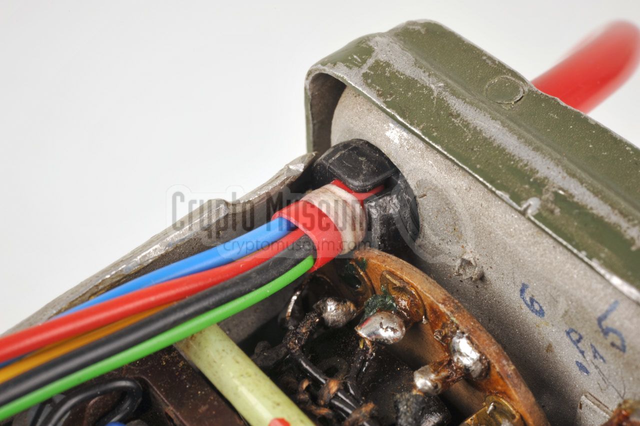
The cables of the CUNZI set featured on this page were replaced by home-made
ones that consist of a red plastic tube with 6 flexible wires inside.
For safety reasons, no attempt is made to use original wires,
as high voltages are present.
|
|
|
The result is a good looking flexible replacement cable, that will last for
the next decades and that can safely be used to replace the old wiring.
Note that the original mains cable may have to be replaced as well, as it is
also made of rubber and will have become brittle over the years.
|
After the cables have been replaced it is best to first check the PSU and
repair it if necessary. If the set has not been powered for several years,
it might be a good idea to re-condition the capacitors by gradually increasing
the mains power from approx. 50V to 220V over a period of several hours
by means of a VARIAC.
Remember that the PSU will only come to life if the transmitter is connected
and switch ON. If you are uncertain about the transmitter's state,
install a dummy plug in socket P1 with a loop wire between
pins 3 and 4, to enable the PSU.
|
|
|
The image above shows an example of a suitable dummy plug. Note that pins
3 and 4 carry 220V AC which can be potentially lethal. Pin 6 even carries
700V DC when loop 3-4 is in place. Make sure that the
pins are properly isolated and do this only
if you know exactly what you are doing.
|
|
For connection between the three units of the BE-20/2,
6-pin LIST connectors were used from post-war Luftwaffe (Air Force)
surplus stock. Sockets and plugs are available in male and female variants
and a notch is present to prevent a plug from being inserted the wrong
way around.
|
|
This is a cable that runs from the transmitter (TX) to the power supply
unit (PSU). At the TX-end it is fixed. At the PSU-end is a 6-pin male
LIST plug that mates with socket P1 on the PSU. The diagram below shows
the pinout of the socket P1 on the PSU, when looking into the socket.
|
- Ground (0V)
- 6V AC
- 220V ~ → to transmitter
- 220V ~ ← from transmitter
- LT +6V DC
- HT +650V DC
|
|
|
P2 is a cable that runs from the PSU to the transmitter. At the PSU-end
it is fixed. At the TX-end is a 6-pin female LIST plug that mates with
the male P2 socket on the transmitter. The diagram below shows the pinout
of male socket P2 on the transmitter when looking into the socket.
|
- ?
- Loop to 6 (in the plug)
- ?
- ?
- ?
- Loop to 2 (in the plug)
|
|
|
P3 is a cable that runs from the transmitter (TX) to the receiver (RX).
At the TX-end it is fixed. At the RX-end is a 6-pin female LIST plug that
mates with the male P3 socket on the receiver. This cable 1 provides power
to the receiver. The diagram below shows the pinout of socket P3 on
the body of the receiver when looking into the socket.
|
- ?
- ?
- Linked to 1 (in the plug)
- ?
- ?
- ?
|
|
-
The antenna signal is supplied by the transmitter via a separate (orange)
wire with a banana-plug at the end. This plug should be inserted into the
socket marked ANTENNA on the receiver.
|
Power 95 - 220V AC, generator 6 - 45V, 6V or 12V DC with inverter
|
Frequency 3 - 5.6 MHz, 5.6 - 9 MHz Sensitivity 2µV (phone), 1µV (CW)
|
Modulation Phone (A3), Telegraphy (A1, CW) Frequency 3 - 9 MHz (crystal) Output 6 Watt (phone), 18 Watt (CW)
|
|
Originally, transmitter, receiver and PSU all had the same serial
numbers, but the units often got swapped in later years.
The following serial numbers have been taken from the surviving devices.
Note that this list does not include the serial numbers of the
BE-20/3 devices.
|
-
Note that this circuit diagram is for the BE-20/1 prototype and does
not fully match the circuit of the production units (BE-20/2). Ignore the
connections of the 6-pin LIST connectors as they are wrong.
Documents kindly supplied by Günter Hütter [3].
|
|
|
|
Any links shown in red are currently unavailable.
If you like the information on this website, why not make a donation?
© Crypto Museum. Created: Saturday 02 July 2016. Last changed: Saturday, 17 December 2022 - 10:24 CET.
|
|

|
|
|


![Two front panel covers. Copyright Günter Hütter [3].](img/gh_lid_1.jpg)