|
|
|
|
|

|
|
Data Gretag ← Portable
Electronic off-line desktop cipher machine
Gretacoder 805, also known as GC-805, is a high-end modular
off-line system for encrypting and decrypting messages,
developed around 1978 by Gretag
(later: Gretacoder Data Systems)
in Regensdorf (Switzerland) as the successor to the
TC-803.
It was one of the first fully electronic microprocessor-based cipher machines.
Due to its modular approach,
different configurations were possible, ranging from a portable device
with thermal printer or acoustic modem housed
in a briefcase, to a desktop setup
with page printer and punched paper tape reader/puncher [1].
|
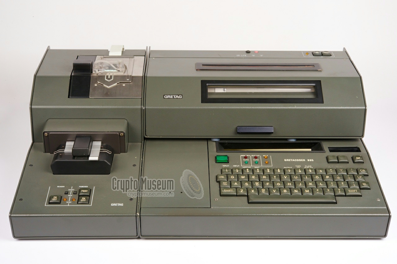
The image on the right shows the desktop version in the common neutral
gray colour. It consists of the main unit,
placed inside an interface cabinet,
a storage box (to the left of the keyboard), a
large page printer (on top) and a
papertape reader/puncher on the left.
The main unit is identical to the suitcase version.
It is microprocessor-based, has a full QWERTY keyboard and a
red alpha-numerical plasma display. The memory
can hold messages up to 4000 characters. The output can be printed on the
wide page printer that is mounted on top.
|
|
|
For security, a two-part cryptographic key was used,
consisting of a 16-character primary key that was entered by the user
and a fixed secundary key that was stored inside a plug-in module.
When in operation, the plug-in module had to be present inside a slot
to the right of the display.
Data can be recorded to the (optional) papertape puncher that was
constructed in such a way that it could be placed at either side of the
main unit. It uses standard 5-hole telex papertape and stores the
information in the common Baudot standard.
A built-in papertape reader can be used to play back
recorded messages. The papertape can also be transmitted by
an external telex.
The portable Gretacoder 805
was a direct competitor to the Hagelin HC-530 that had a similar appearance.
The 805 is a very rare item of which only of few
suitcase versions have survived. The desktop version
(shown here) has been rediscovered in 2012 and as far as we currently
know, it is the only one that has survived.
Although the Gretcoder 805 was a very popular cipher machine in the
late 1970s and the early 1980s, we don't know how many units were
eventually sold.
➤ Check out the portable version
|
PLEASE HELP —
We are still looking for the User Manual and the Technical Manual of
the Gretacoder 805. If you have any of these, please contact us.
Especially the user manual would be greatly appreciated as we want to bring
the machines back to life again. Any other kind of help would also
be much appreciated.
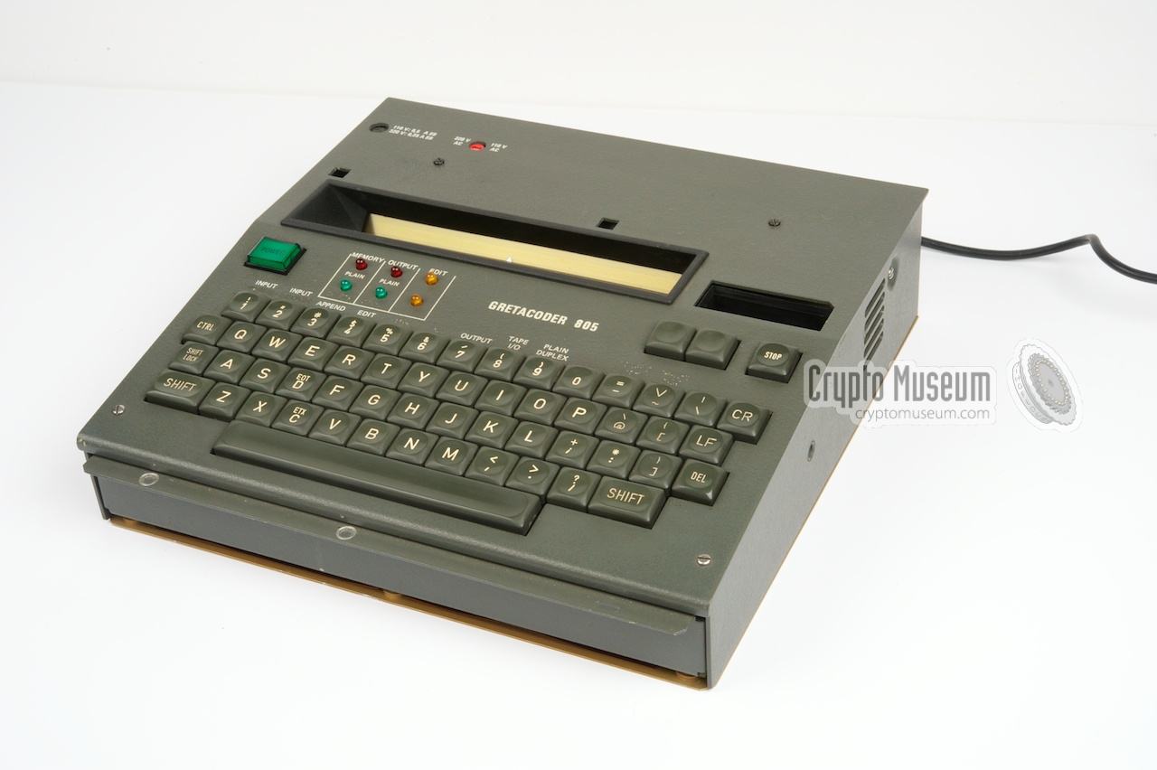
The microprocessor-based Gretacoder 805 has a full QWERTY keyboard for
message input. Output is via the 37-character smooth scrolling plasma
display or through an external printer.
Upgrade kits, consisting of a replacement keyboard
and a set of EPROMs, were available for other languages such as Arabic.
An example of the latter is shown in the full-colour brochure [2].
The unit is turned on with the green button at the top left of the keyboard.
The unit featured on this page is currently not functional. It contains
a very early motherboard (probably a prototype) with five 2708 EPROMs of
1KB each. Furthermore, the EPROMs contain a different kind of software than
other machines in this series. This software was probably intended for
demonstrations or for generating punched papertapes only
(more about this below).
|
|
The main unit of the desktop station is identical to that of the
portable version, except for the colour of its body.
It is basically a small computer in a single case, consisting of a
motherboard, a keyboard, a plasma display, a slot for the secundary key,
and a built-in Power Supply Unit (PSU).
|
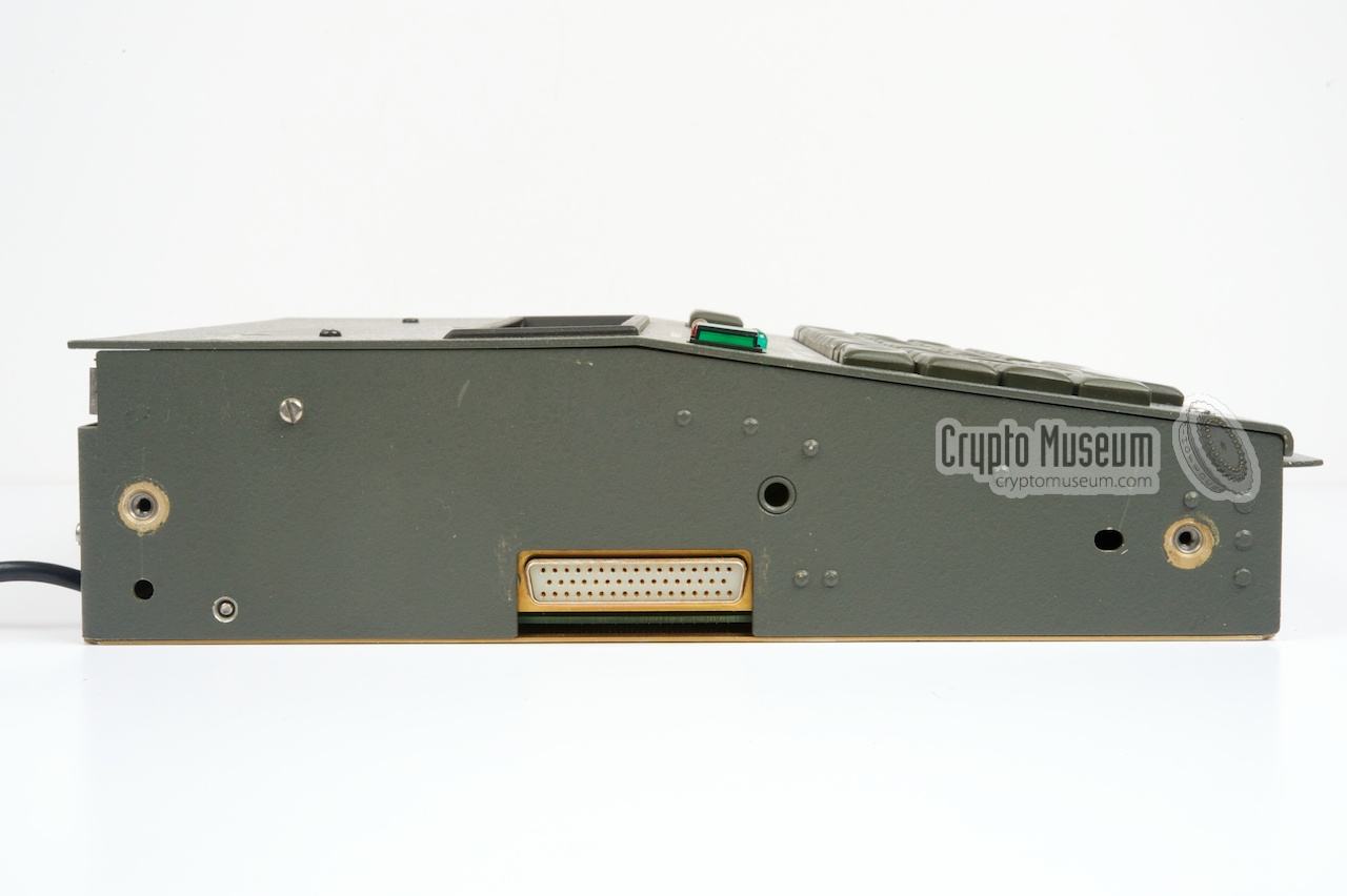
The image on the right shows a typical GC 805 main unit in a
neutral grey case. A fixed power cable is present at the rear
to connect the unit directly to the mains.
At the left side is a large 50-pin
D-type connector that allows the connection of a peripheral, such as an
acoustic modem, a telex interface or small printer.
At the rear is another large connector
that allows an external papertape reader/puncher to be connected.
For desktop use, the main unit is installed inside a
large metal interface frame that makes the
whole unit wider and deeper.
|
|
|
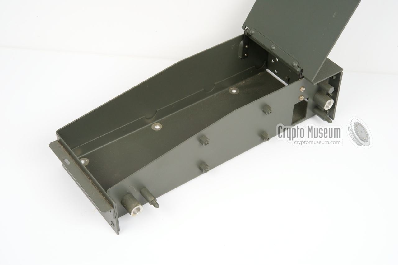
The empty space to the left of the main unit can be filled by an
(optional) peripheral or interface, but also by an
empty storage box
as in the example shown here. The storage box is bolted to the left
side of the main unit. Due to its large lid, it can only
be opened when the
page printer is not mounted on top of the unit.
More information about the optional interfaces
can be found below.
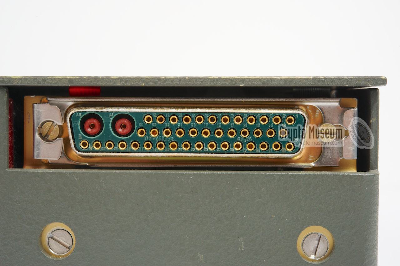
The large connector
at the rear of the main unit is extended by the
interface frame to a similar connector
on the top surface,
allowing the wide page printer to be placed directly over it.
The page printer is constructed in such a
way that it mates directly with this connector. The connector carries all
the (parallel) data lines and even the 220V AC mains, so that no cables
are required.
|
|
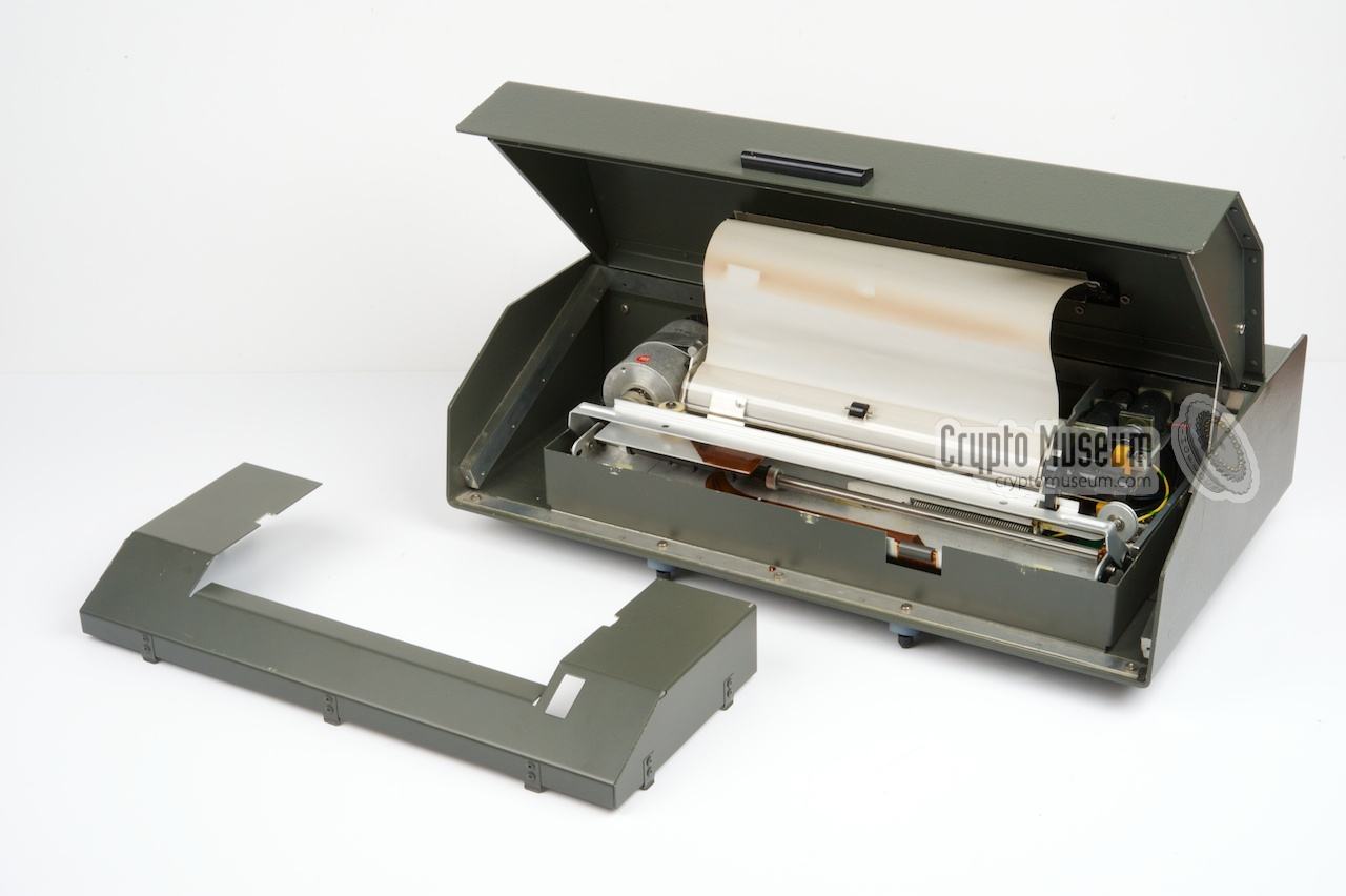
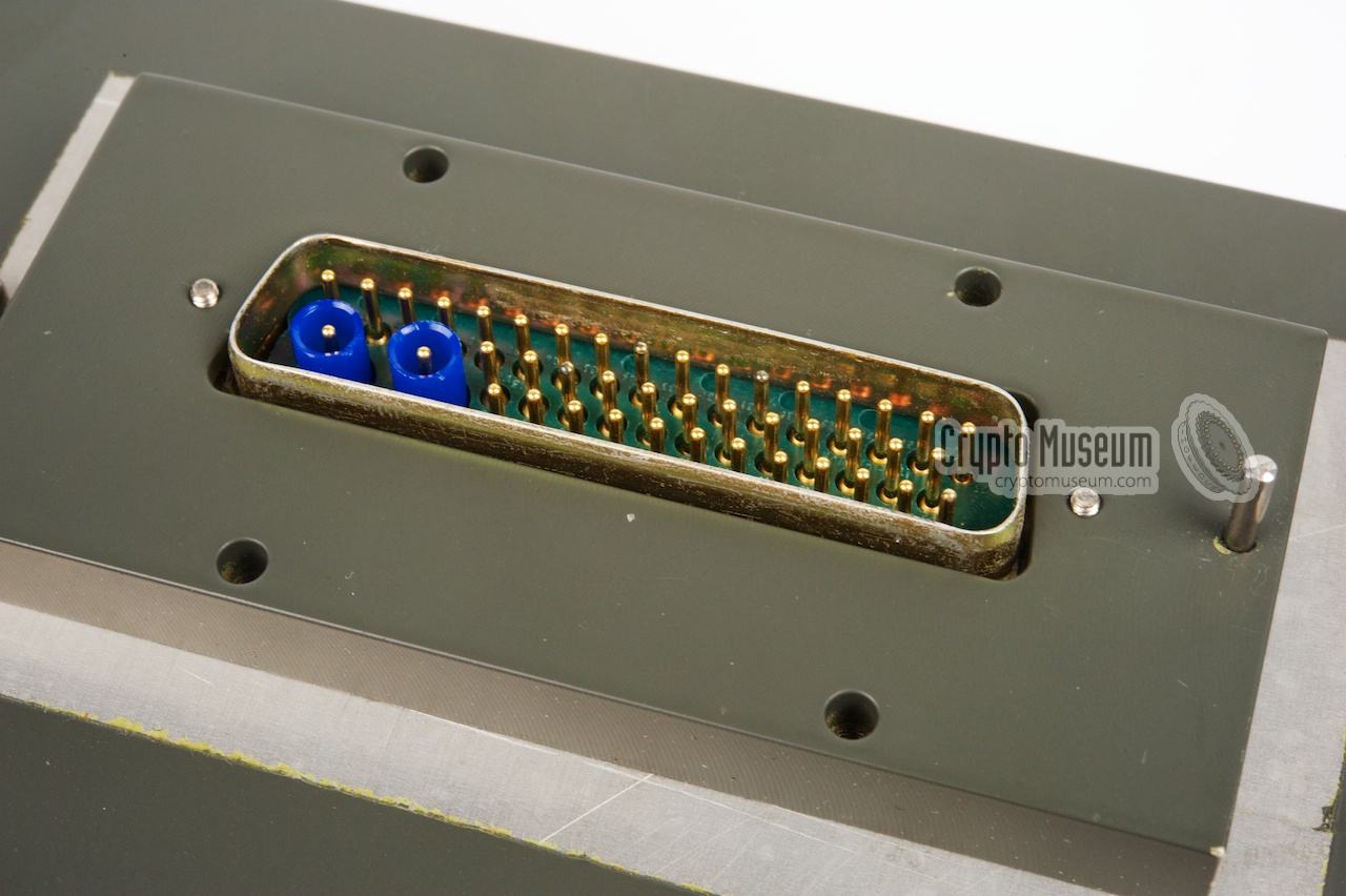
For desktop use, the PP-805 full 80-column wide page printer can be installed.
It is placed on top of the main unit and is hold in place by a lock at
the rear. The unit is connected to the interface frame by means of a
large D-type connector
at the bottom that also carries the 220V lines.
|
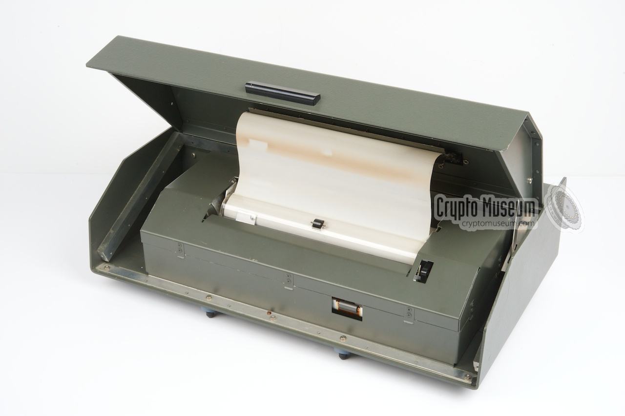
The image on the right shows the wide PP-805 printer, which has the same
width as the frame (i.e. the main unit plus the storage box). It has four
pins at the bottom for holding it in place.
The two at the front mate with
two square holes in the top cover of the main unit (just above the display),
whilst the two at the rear mate with the frame, producing a click
when properly seated.
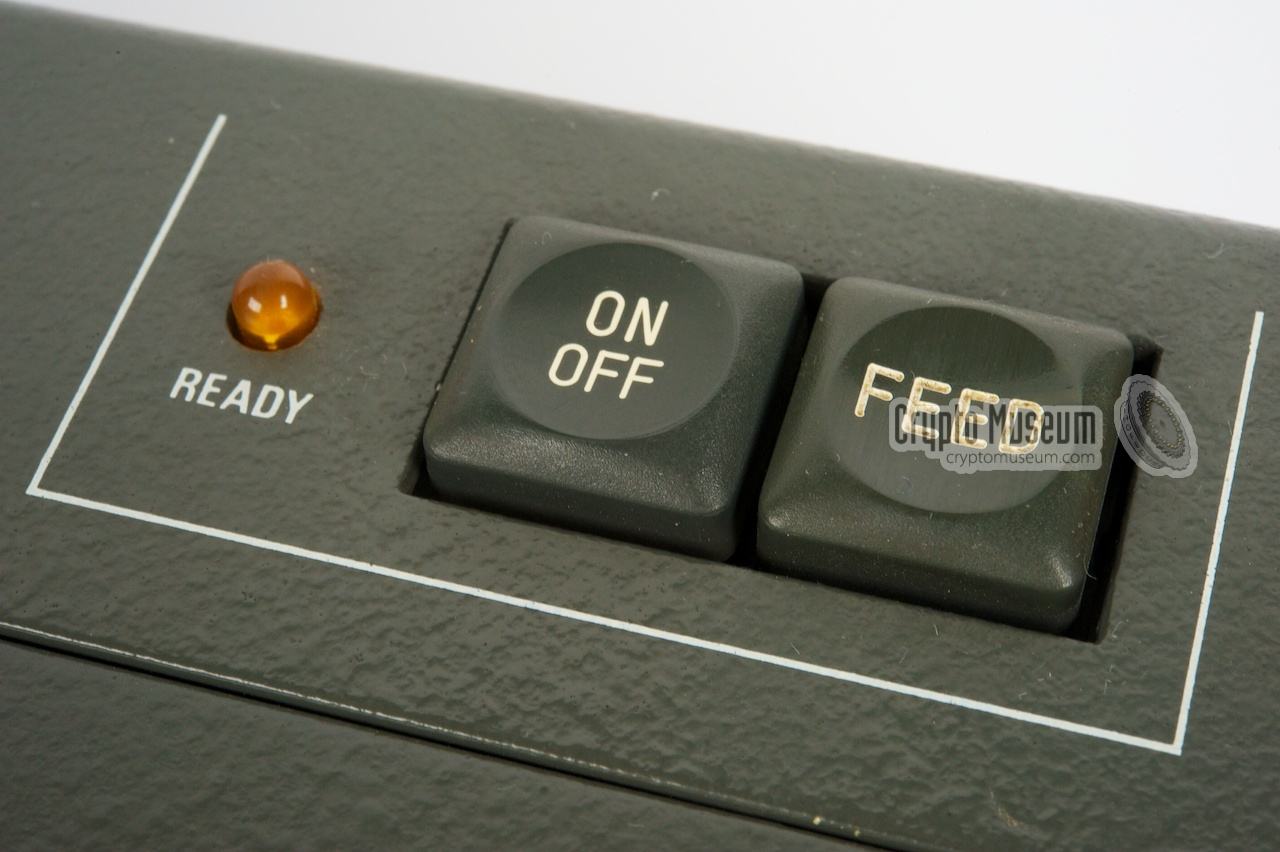
The printer requires no cables and is normally controlled by the main unit.
The only controls are the two buttons
at the top right: the power switch
and a push-button for feeding the paper.
|
|
|
|
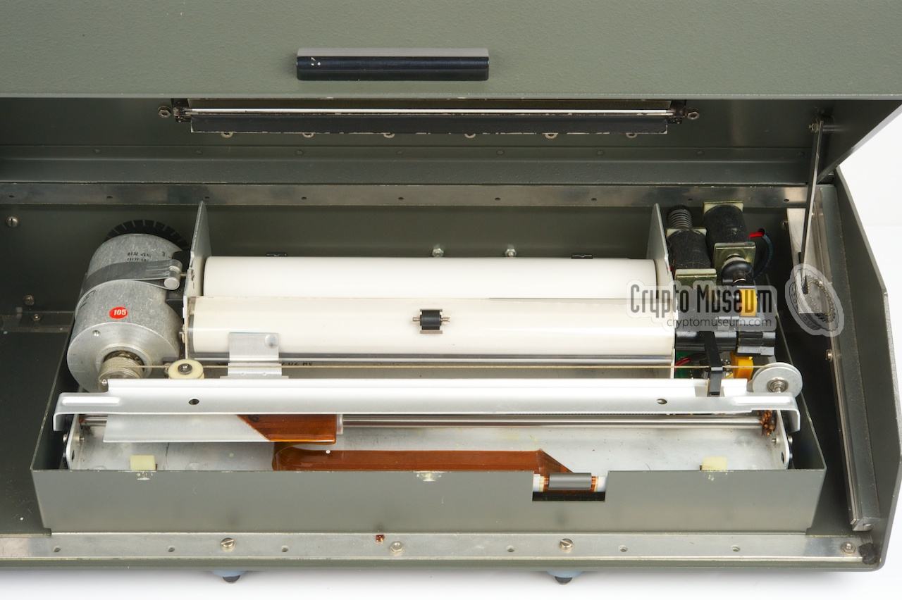
The printer case can be opened
by raising the metal cover with the handle
at the front. This gives access to the actual printer itself, which is
slightly smaller than the case. A thin aluminium cover protects the
printing machanism. It is fitted to the case by means of a series of
springs around the edges.
Inside the case is a thermal printer with
a rather large motor at the left.
The unit prints to 21 mm wide thermal paper that was commonly
used with fax-machines in those days.
|
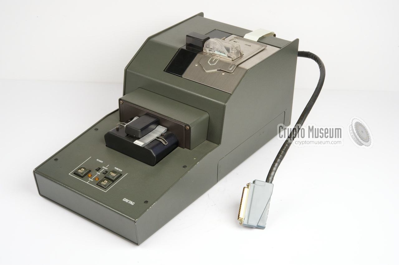
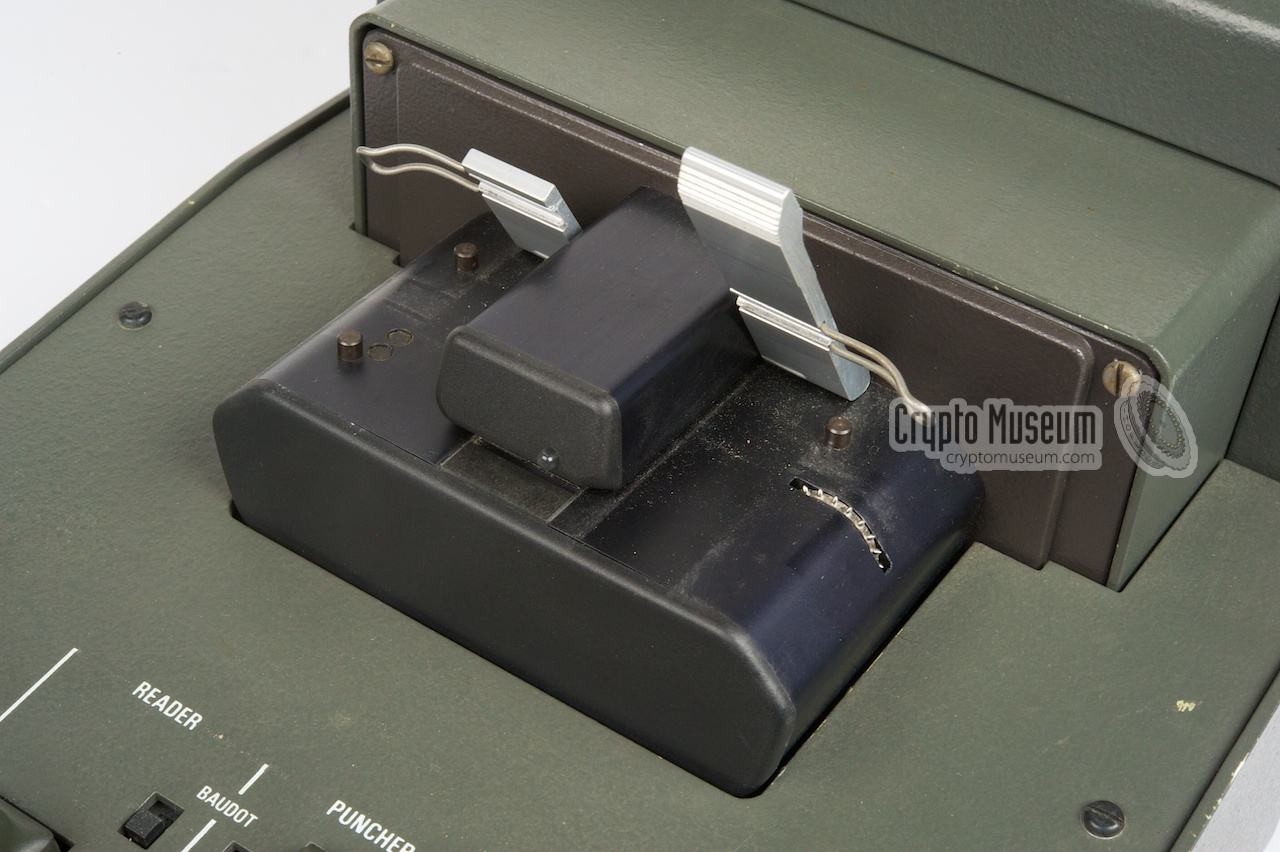
Plain or encrypted messages can be recorded onto papertape by using the
(optional) RP-805 papertape reader/puncher, that is constructed in such a
way that it can be placed at either side of the main unit.
It connects to the main unit by means of a large D-type connector that is
fitted at the rear. It also carries the mains voltage.
The RP-805 also contains a papertape reader at the front. It can be used to
play back previously recorded messages. It can also be used for the encryption
of messages that are prepaired on an external teleprinter or telex
machine (off-line).
|
|
|
|
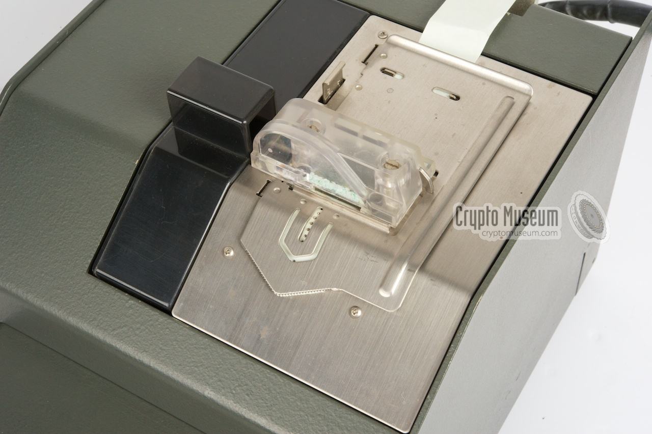
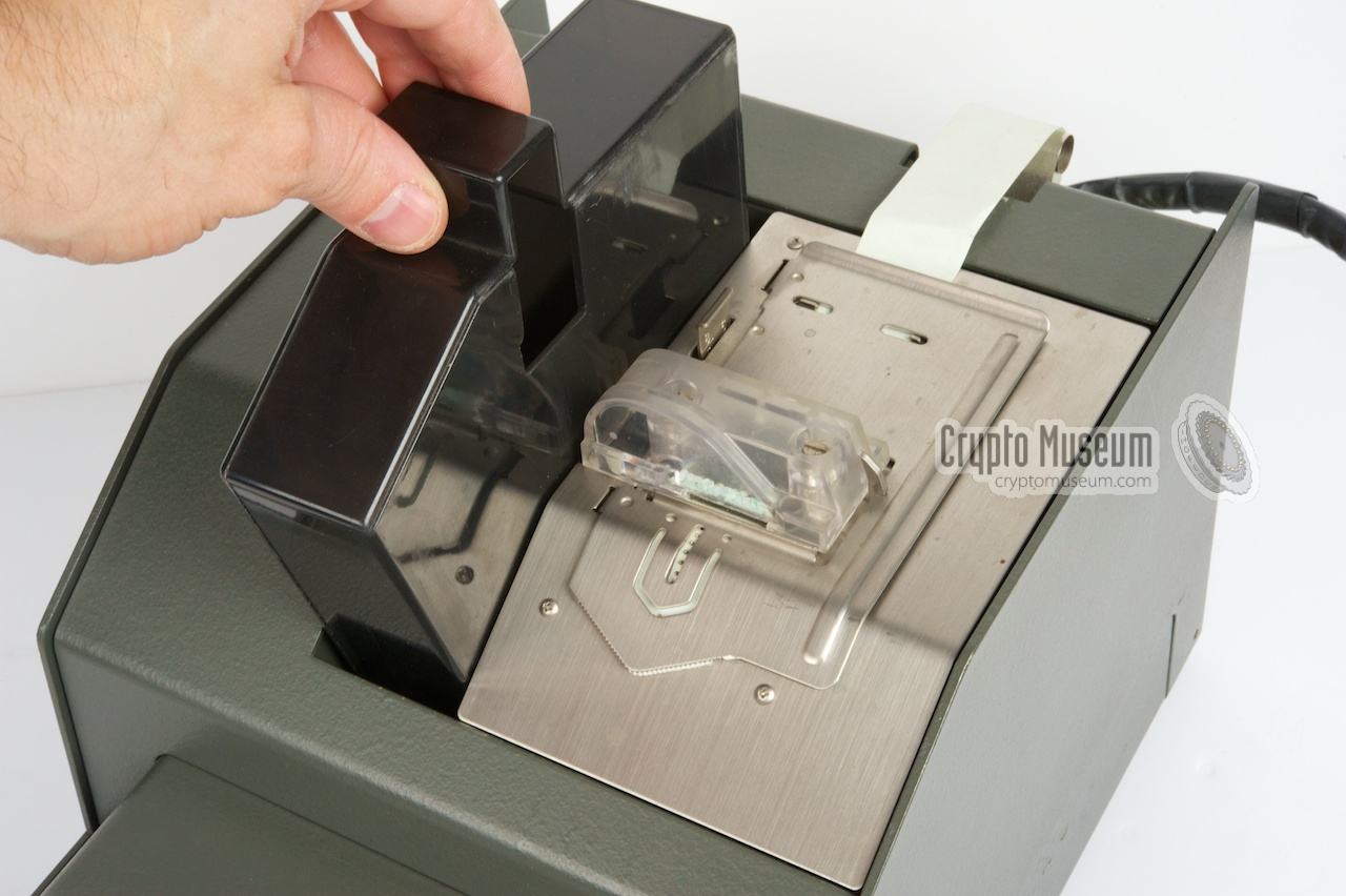
The unit uses standard 5-hole papertape and follows the common
baudot standard.
Supply of fresh paper is from a drawer at the bottom of the unit.
The drawer can be opened from both sides, allowing the reader/puncher
to be placed either at the left
or at the right of the main unit.
|
|
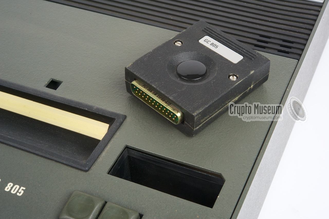
The cryptographic key of the Gretacoder 805 is made up of three individual
components: a 16-character alpha-numerical string that is entered on the
keyboard (primary key), a fixed secundary key that is stored in a plug-in
module (crypto ignition key, or group key), and a modifier key.
|
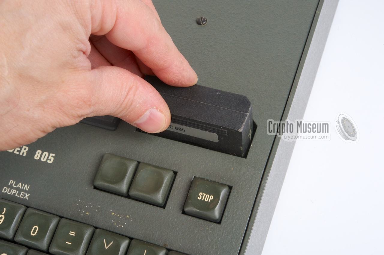
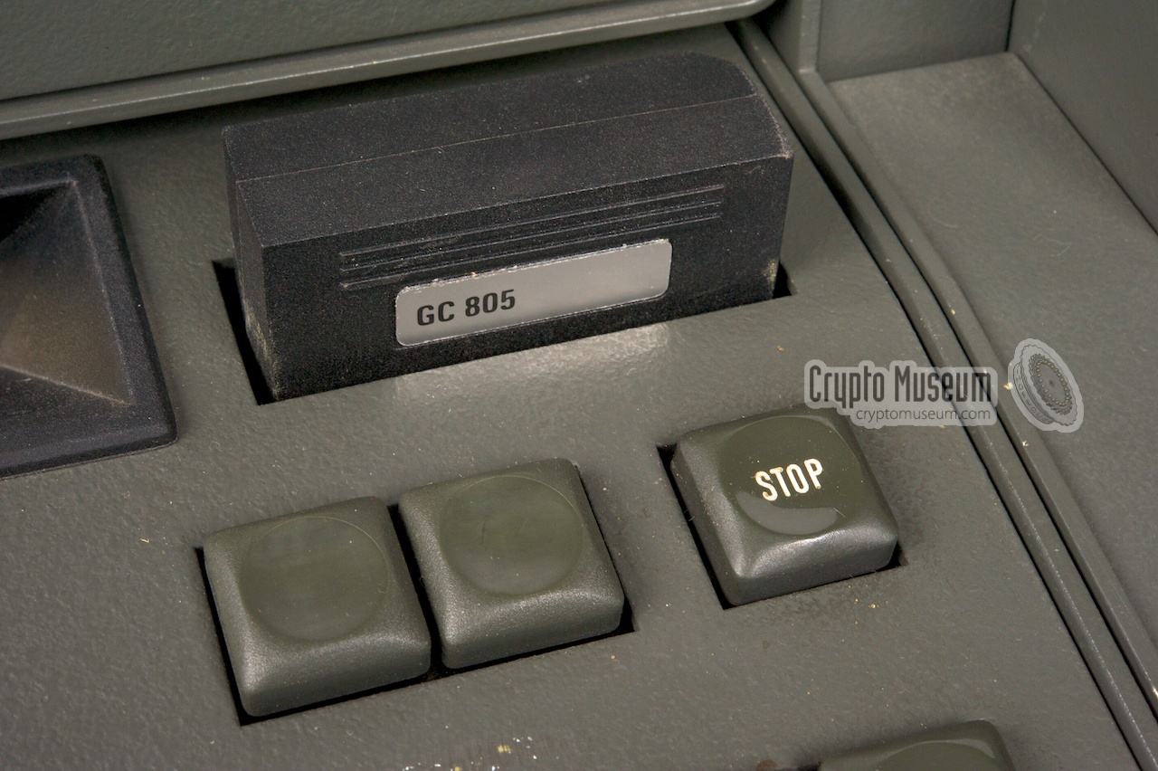
The primary key is variable and should be entered by the user on the
keyboard. The secundary key is fixed and is stored in a small plastic
module that is fitted into a slot at the upper right of the keyboard.
Without this plug-in unit, the Gretacoder 805 can not be used.
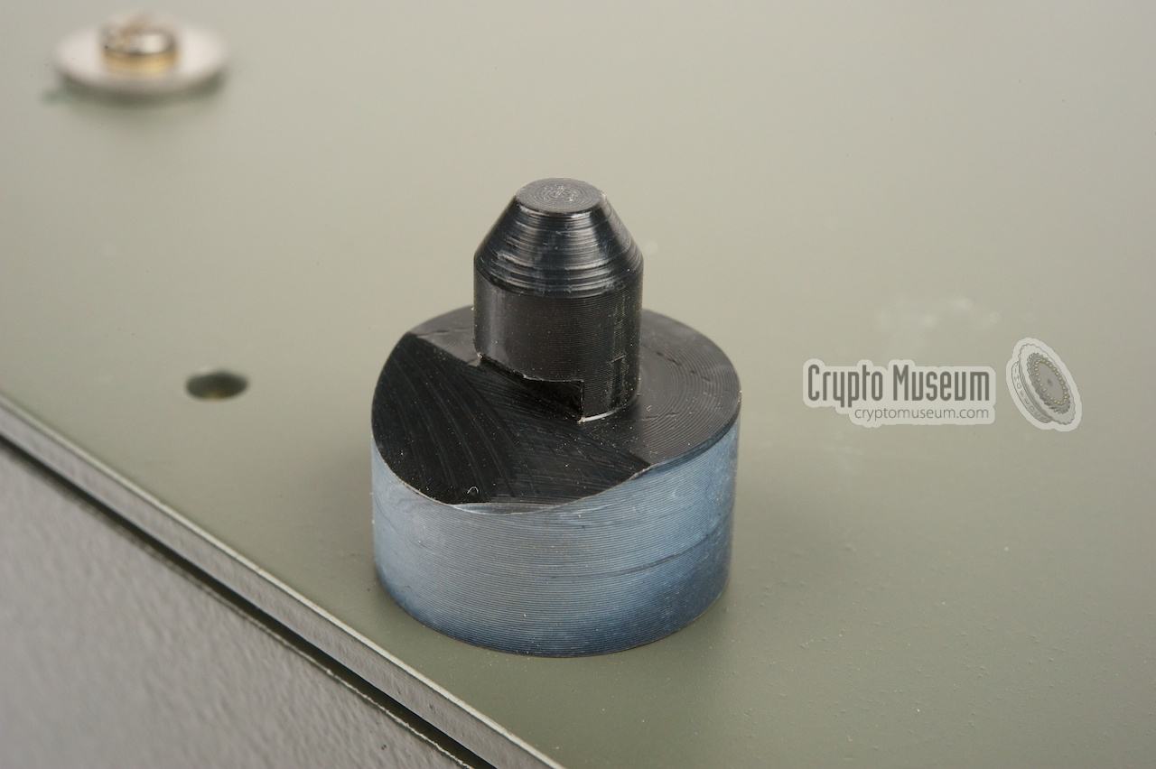
The image on the right shows the interior of the secundary key, which
consists of the very first 24-pin 1702 EPROM (256 bytes) connected
to a DB-25 connector.
In order to communicate with another Gretacoder 805, both machines
need to have an identical secundary key module [4].
|
|
|
|
Secundary keys offer a way of customization. At the time, users could order
pre-programmed sets of key modules from Gretag. For larger customers a
special programming kit was available. It could be used to generate new
unique keys and to make duplicates from existing keys [2].
|
The Gretacoder 805 had a truly modular design, which made it possible to
create a variety of solutions, ranging from a highly portable
briefcase version, to the fully fledged desktop workstation
featured on this page.
The main unit, i.e. the electronic micro-processor-based crypto heart of
the 805 family, was used in every version. The various modules were available
in two colours: bright yellow (as shown below) and neutral grey.
The basic modules are shown here:
The main unit could be fitted inside a slim-line
Samsonite briefcase of the era, together with an
acoustic modem or a miniature thermal printer.
For the desktop version a larger interface case was available.
It could hold the main unit, plus
one add-on unit to its left. A large page printer could be placed on the
top and an optional paper-tape reader/puncher could either be placed
on the left or on the right [2].
An example of the desktop version is shown at the top of this page.
|
- Main Gretacoder 805 unit
- Acoustical coupler
- Telex interface
- Empty case (for desktop version)
- Miniature thermal printer
- Desktop interface (for desktop version)
- Page printer
- Papertape rader/puncher
- Samsonite attache case (for the portable version)
|
|
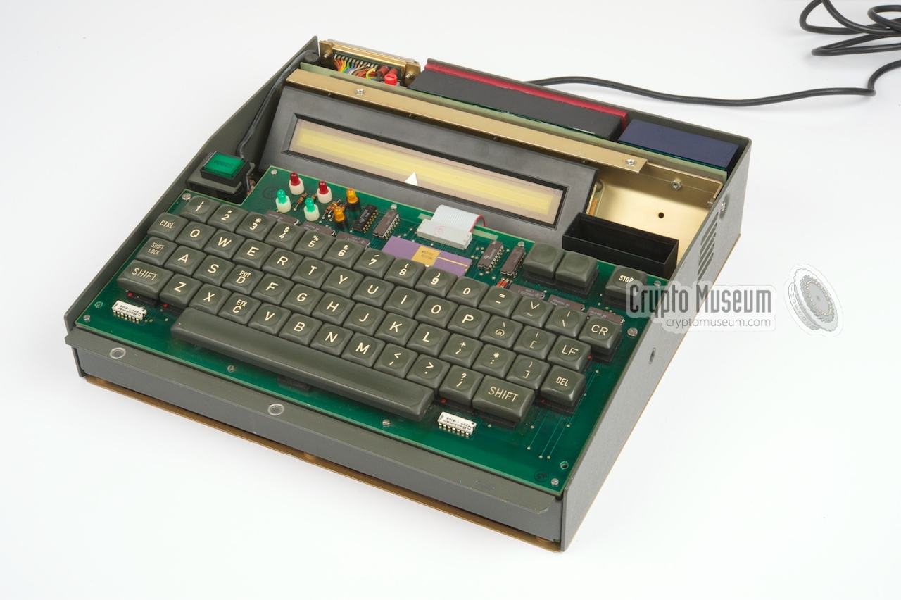
The Gretacoder 805 is well built and contains only first-class electronic components. After removing the top cover, the interior becomes
visible. The electronics consists of a large motherboard at the bottom,
a separate keyboard and a set of power supplies at the rear.
|
The unit shown here was built around 1979.
The main circuit is built around an AM9080A micro processor,
built by AMD in 1977 [5]. This is basically a military version of the popular
Intel 8080A. On later versions of the motherboard the P8080A was often used.
To the left of the 8080 is an SN74S428N controller/bus driver [7].
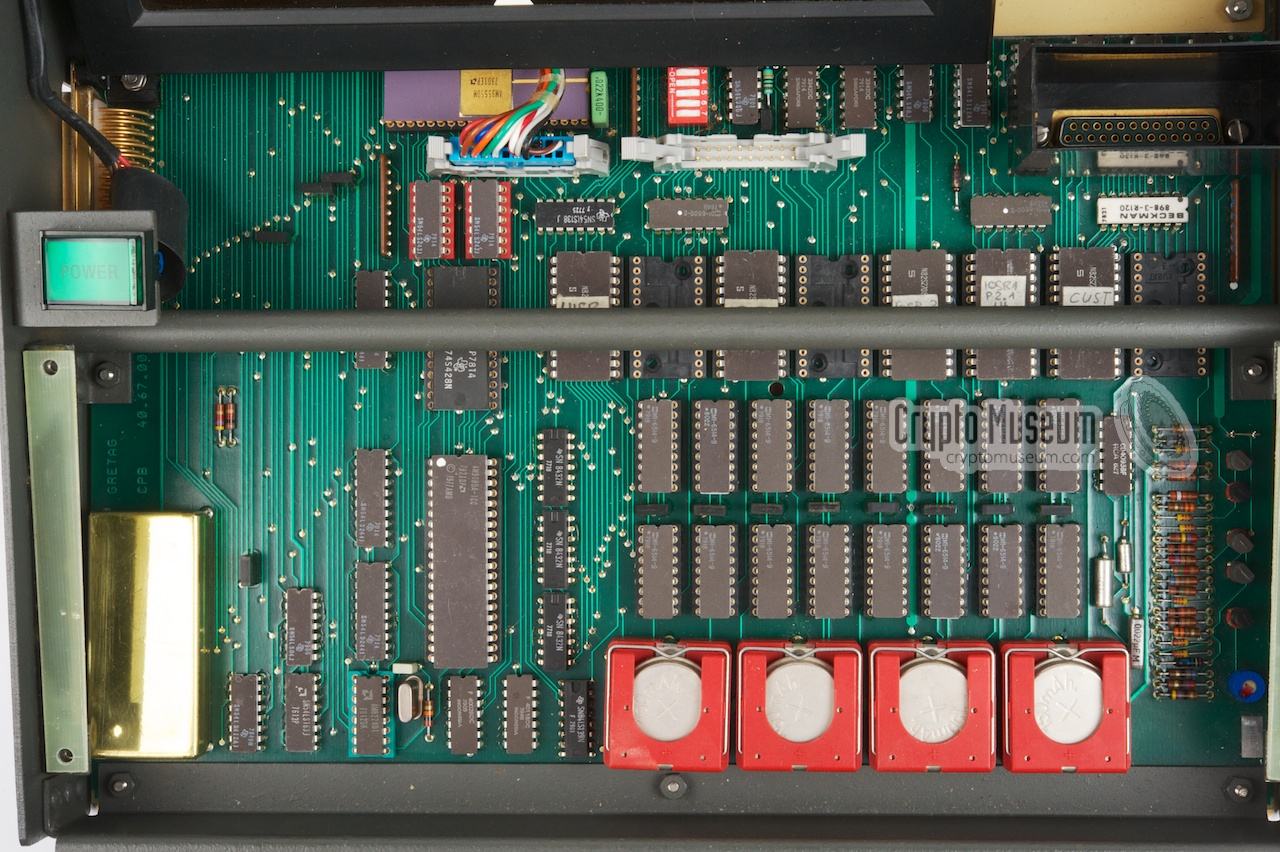
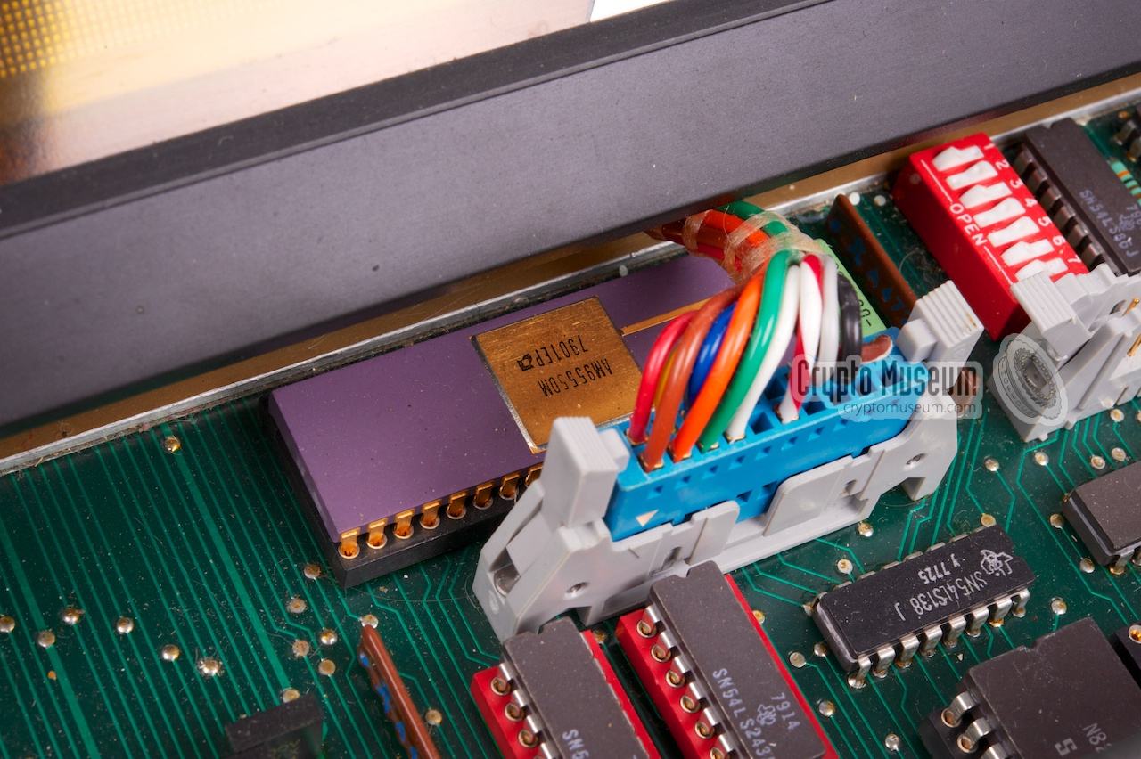
The image on the right shows the keyboard with an AM9555DM peripheral
controller. This is an early version of the popular D8255 that was used in later
versions of the machine [6]. The ribbon cable connects it to the motherboard.
|
|
|
The unit features 8KB of static RAM, consisting of 16 memory chips of the
type HM-6514/9, that contain 1024 x 4 bits each. As this is static memory,
it can be retained by a set of rechargeable NiCd cells when the machine
is switched off The cells are mounted in front of the RAMs [8].
To the rear of the RAM chips are 8 sockets for ROMs or EPROMs.
In the first release of the motherboard 1KB EPROMs were used (2708),
but in later version only three 4KB types were used (2732). The other
sockets were not populated. These larger EPROM can not be fitted on the
older motherboards, due to an error in the PCB layout.
This problem is fixed in later versions.
|
The machine featured on this page is currently not functional.
It is equipped with a different set of EPROMs than our
portable version, has an older type of motherboard
(probably a prototype) and has no dongle.
Furthermore, some of the text above the top row of the keyboard
has been removed. It is likely that this machine
was used as a data-entry station for punched tape.
In the meantime, please refer to the portable version
for more information about its operation.
The challenge is now to restore the machine to its full glory again.
This involves modifying the motherboard to accept the larger EPROMs
used in the later machines, making copies of the existing EPROMs
and creating a replacement plug-in module for the secundary key.
Whenever we have made some progress, we will report it on this page.
|
|
The following machines are known to be compatible with the GC-805:
|
- Briefcase version of the above machine
Gretacoder 505 TTY encryptor - Pocket cipher machine with LCD
SP-300/GCA Huge teleprinter-style cipher machine
|
|
Although the Gretacoder 805 is not compatible with any other brand
of cipher machines, there are some machines of the same era that show
great resemblance to it. For example:
|
Algorithm Proprietary non-linear stream cipher Keys Primary key: 16 characters 1
Secondary key held in EPROM plug-in unit Key space ~ 1060 Keyboard ASCII, Baudot Display 37 character, smooth scrolling plasma display Memory Battery backed
4033 characters plaintext
7563 characters ciphertext
8 primary keys 1 Option Arabic Temperature 0°C to +50°C Storage -25°C to +70°C Dimensions See below Weight See below
|
-
different primary keys can be held in memory simultaneously.
|
Power 96-253V AC Dimensions 470 × 340 × 95 mm Weight 8 kg
|
Power 97-126V and 87-253 V AC Dimensions 460 × 430 × 180 mm (with printer) Weight 13 kg
|
|
|
Paper tape reader/puncher
|
|
|
Standard ITA-2 Dimensions 460 × 200 × 180 mm Weight 8 kg
|
- Jane's Military Communication 1986
ISBN: 0-7106-0824-1
|
|
|
|
Any links shown in red are currently unavailable.
If you like the information on this website, why not make a donation?
© Crypto Museum. Created: Thursday 05 July 2012. Last changed: Sunday, 14 January 2024 - 11:37 CET.
|
 |

|
|
|


