|
|
|
|
|

|
|
Radio CS
Body wearable alarm transmitter
Poplach 1 was a body wearable alarm transmitter developed in the late
1950s or the early 1960s in
Czechoslovakia
by Správa 6 2 for use in
covert surveillance operations.
It was often used as a counter-counter
measure (CCM),
for example: to warn a spy that he or she was being followed.
The transmitters were used by the
secret intelligence agency (StB)
and by Správa 1 (espionage).
|
The complete set consisted of a body wearable transmitter with a hand-carried
remote control unit, and a receiver with an
external vibrator.
The fully-transistorised transmitter worked in the 27 MHz band
and was crystal operated.
The image on the right shows a typical Poplach alarm transmitter
with the matching remote control unit (RCU).
The transmitter was hidden on the operator's body
and used a wire antenna.
The RCU unit was carried in the hand,
with the cable
running through the sleeve of the coat.
The RCU-cable was connected to the transmitter.
|
|
|
Like the transmitter, the receiver was body-wearable and used a wire-antenna,
so that it could be concealed under the operator's clothing. Rather than using
an earpiece, which would certainly be noticed by an observer,
an external vibrator
was used to send a 'signal' to the operator.
In order not to miss an alarm, the vibrator had to be carried
close to the body, e.g. behind the waist belt.
|
The use of the Alarm Transmitter is probably best illustrated with an example.
When an agent had a meeting with, say, an informant, he had to be certain that
he was not being followed. He therefore had a colleague who followed him
unobtrusively to see if he was being shadowed.
If the follower didn't trust the situation,
he raised the alarm by pressing the small button on the remote control unit. The recipient felt the vibrator going off continuously,
and immediately aborted his mission by walking on and ignoring
his informant. They would try again later.
|
|
|
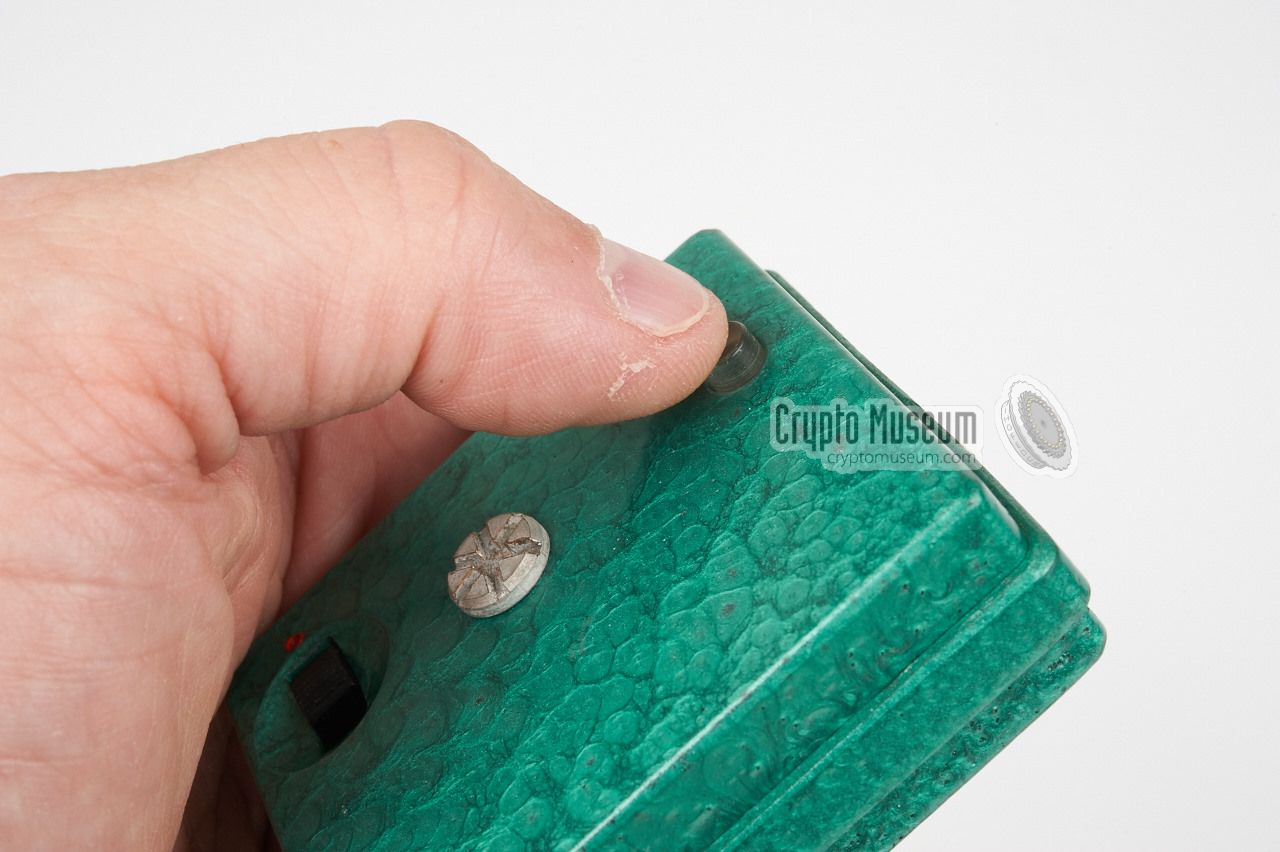
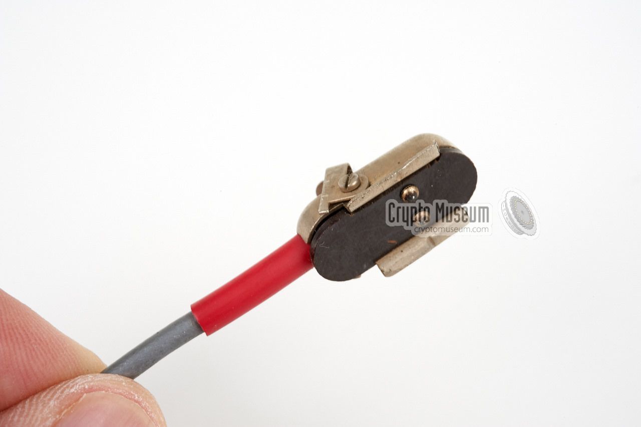
In order to ensure that the agent's alarm receiver is still within
reach of the follower's alarm transmitter, a clever solution was developed.
After switching on the transmitter with the slide switch on the remote
control unit (red dot is ON), the unit is armed and will send a
short signal every 3 seconds. The agent then knew that the situation was
OK and that he could proceed.
If the agent and the follower got separated,
the signal would be lost and the vibrator in the agent's pocket
would no longer vibrate every 3 seconds.
If the follower suspected an insecure situation, he pressed
the push-button on the remote control unit, causing a continuous
signal to be sent. As a result, the agent's vibrator would buzz
continuously and he knew he should abort.
|
 |
-
The name Poplach is probably incorrect, but as the devices are unmarked,
we have used this as a nickname. Poplach is the Czech word for 'alarm'
and is also used for other Czechoslovakian alarm transmitters.
-
Správa 6 refers to Government Department 6: Communication Technology.
|
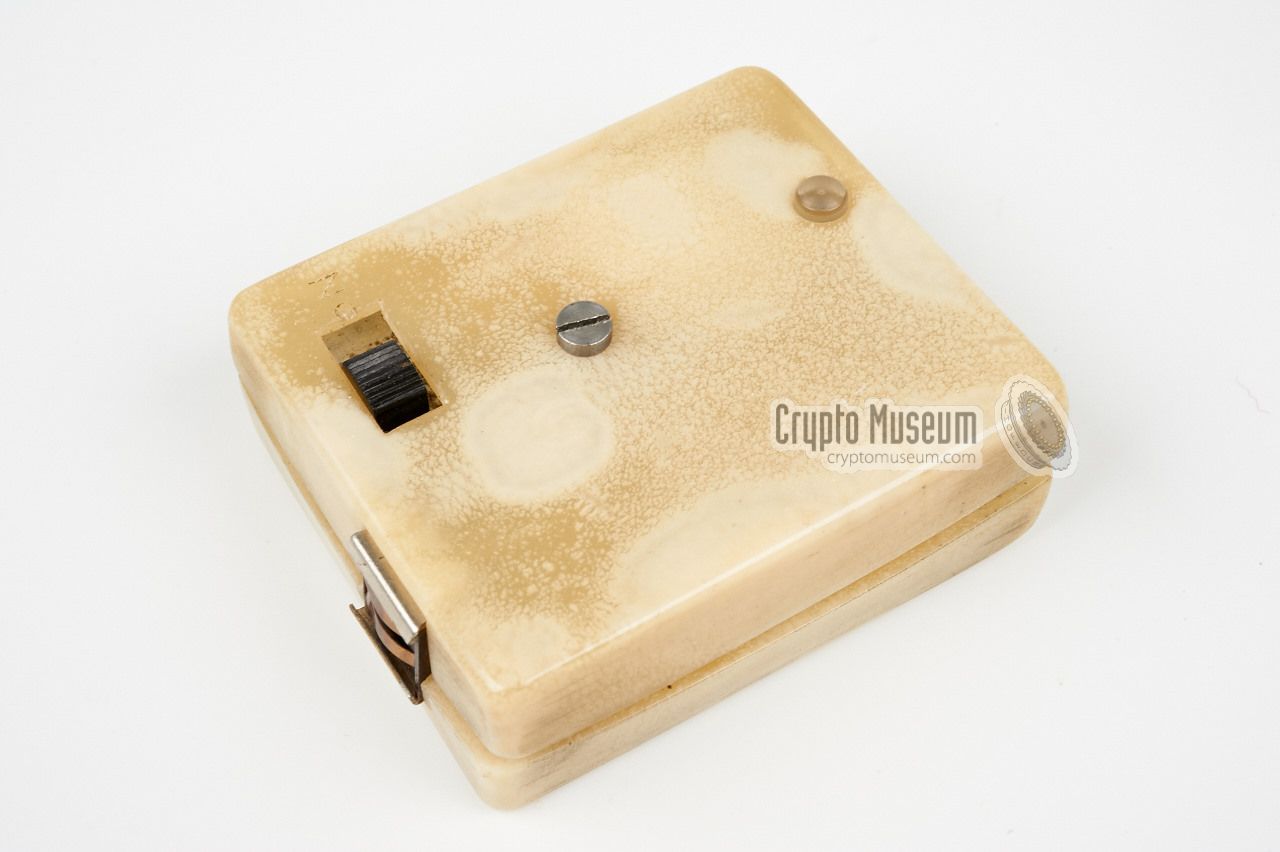
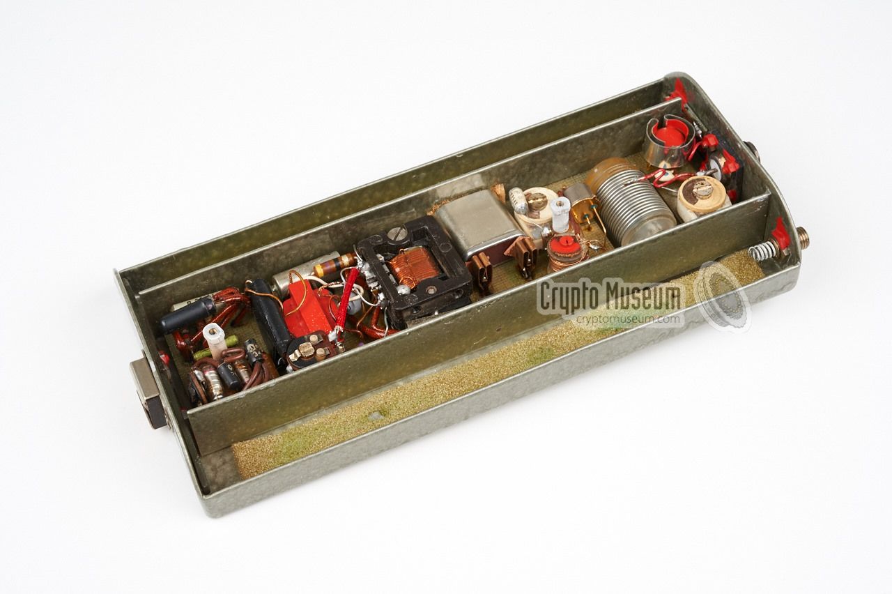
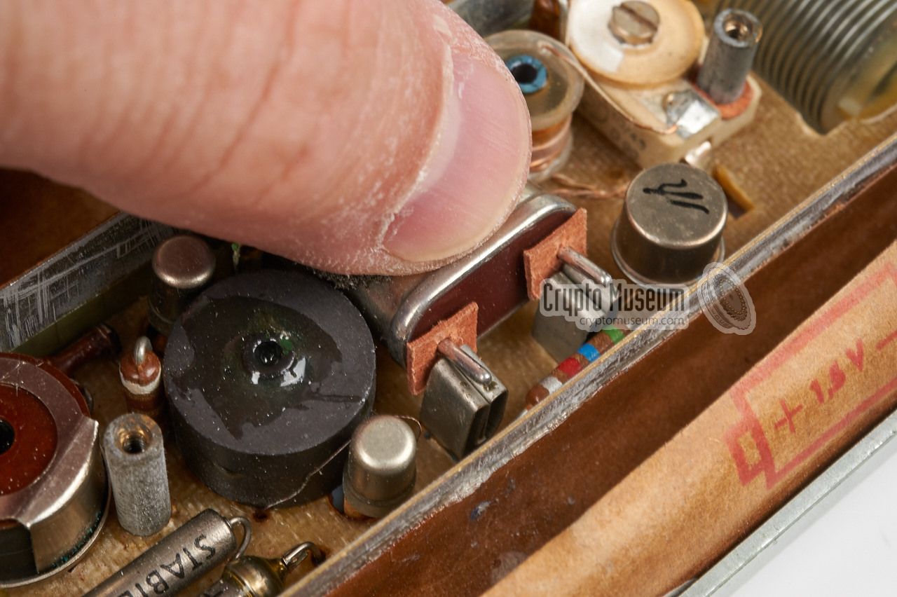
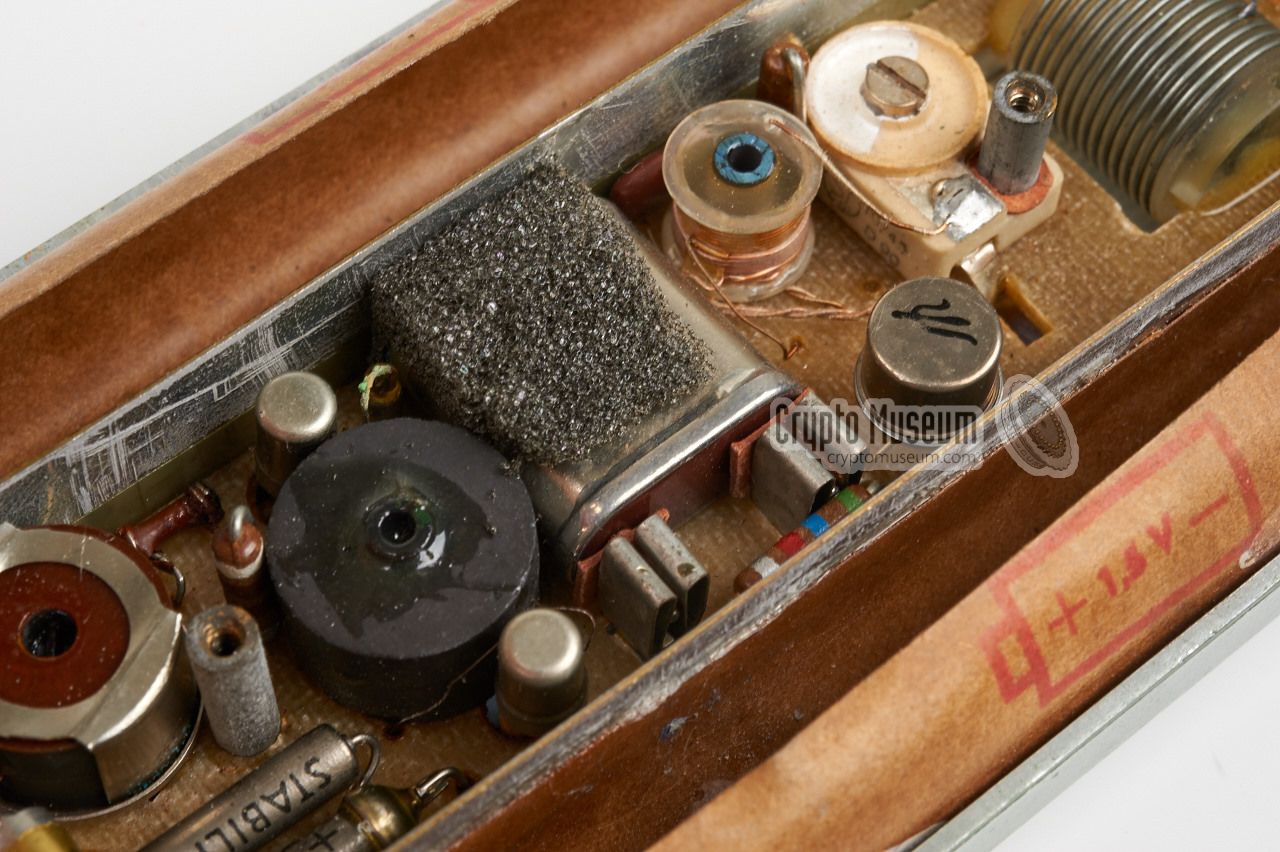
The diagram below shows a complete and operational alarm transmitter.
The unit shown here works at 27.075 MHz 1 and uses a wire antenna that
should be hidden under the operator's clothing. The small plastic remote
control unit (RCU) should be carried in the hand with the detachable cable
running through the sleeve. The RCU could also be carried in a coat pocket.
Both units are battery powered. The transmitter takes six 1.5V AA-size
cells (three at either side) and the remote control unit (RCU) takes another
two. The latter was necessary as the early version of the RCU contains the
generator that produce the intermittent vibrator signal (e.g. 1:3 sec).
Different vibrator patterns could be used for different followers.
A later version of the RCU took its power (4.5V) from the transmitter,
by using an extra wire in the sleeve cable.
|
|
-
The transmitter operated in the 27 MHz band, which is also known as the
Citizen's Band (CB). Although this band was highly used during the 1970s
and 1980s, it was very quiet in the 1960s, which is probably why this
band was used for the Poplach. In Europe it was mainly used for
controlling model airplanes and boats.
|
|
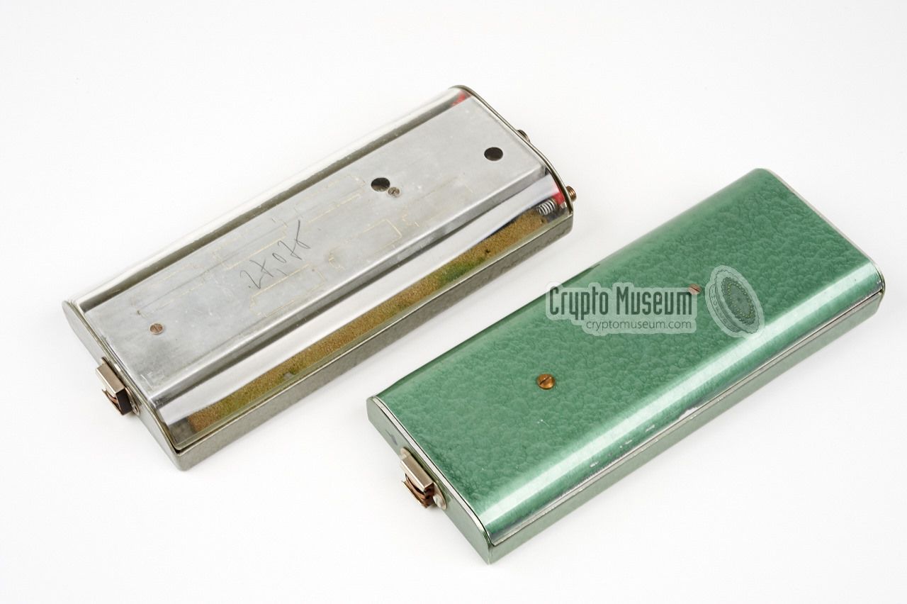
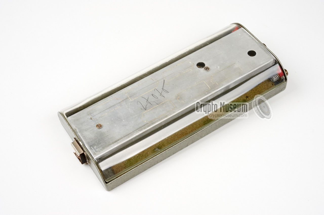
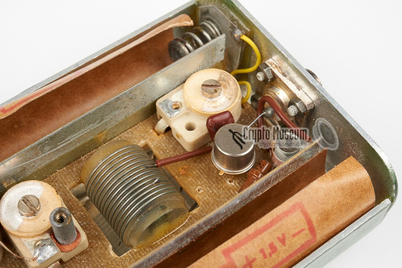
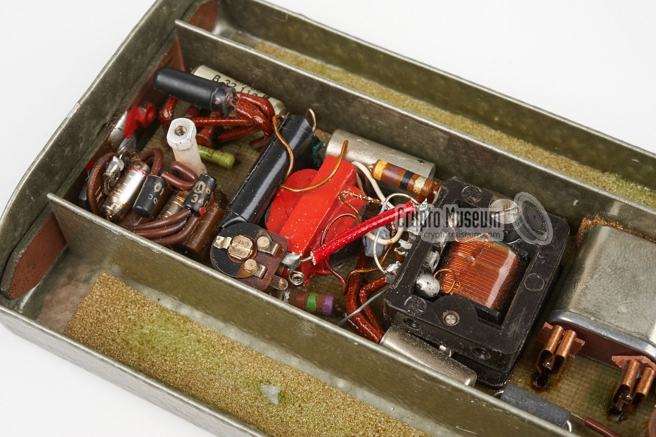
At least two variants of the 'Poplach' have existed. An older one, in a grey
hammerite enclosure and a transparent lid, and a newer one in a fully
aluminium green hammerite case. The latter was
slightly smaller and used more modern components,
but was otherwise identical to the older one.
|
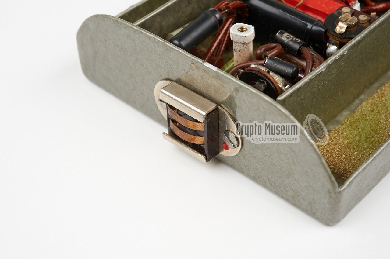
The antenna output is at the far right and, rather than using a properly
tuned antenna, a simple wire is used.
This causes a mis-match and
significantly reduces the operational range of the transmitter,
but has the advantage that it
can easily be concealed under a person's clothing.
The reason for choosing the 27 MHz
band for this application is probably the fact that it was a very
quiet band in the 1960s, and crystals for it were readily available
on the American CB market.
|
Below are the circuit diagrams of the Poplach transmitter and the remote
control unit. When enabled, the transmitter sends a continuous
AM-modulated tone that triggers the vibrator in the receiver. The transmitter
is enabled by connecting the two battery sections at the botton, which is done
by the RCU unit. Inside the RCU is a pulse generator with an adjustible
duty-cycle.
The initial version of the RCU was self-powered and used two 1.5V AA-size
batteries that were installed inside the unit. This variant is shown in the
leftmost diagram. A later version used the 4.5V from the rightmost battery
section of the transmitter, simply by using an extra line (GND) in the
sleeve cable (rightmost diagram).
As a result, the RCU was only half the size of the old one.
|
We are currently unable to show the block diagram of the receiver,
as we don't have the original receiver in our collection. It is known however,
that it was used in combination with a concealed wire antenna, plus a
concealed vibrator unit that was carried against the body. Like his:
|
Device Body wearable alarm transmitter Purpose Covert surveillance, detection run alarm Model Poplach 1 Manufactuer Správa 6 Year 1958-1961 ~ Country Czechoslovakia Users Správa 1, StB Frequency 27.075 MHz Output ? Power 9V DC (+ 3V in older model) Dimensions ? Weight ?
|
- Alarm transmitter
- Remote control unit (RCU)
- Sleeve cable
- Wire antenna
- Batteries
- Alarm receiver
- Vibrator
- Wire antenna
- Batteries
|
-
Not the real name, but a nickname given by Crypto Museum.
|
- Anonymous, 'Poplach' - Alarm Transmitter - THANKS!
Device kindly donated by anonymous former user. July 2015.
|
|
|
|
Any links shown in red are currently unavailable.
If you like the information on this website, why not make a donation?
© Crypto Museum. Created: Friday 07 August 2015. Last changed: Monday, 15 December 2025 - 10:33 CET.
|
|

|
|
|