|
|
|
|
|

|
|
RDF Telefunken BND
The device is housed in a stainless steel case that carries a working
mechanical windup wristwatch, with an analogue dial behind a glass window.
The actual transmitter is hidden behind the movement 3 along with
two batteries, and uses a leather-covered metal bracelet as its antenna.
The device operates in the 2-metre VHF-H band, at a crystal controlled
frequency between 155 and 175 MHz.
The unit shown here operates at 168.3615 MHz, which
lies in between the naval band (153 MHz) and the regular band used by the
emergency services at the time (172 MHz). 4
|
|
|
The device is also known as an distress-transmitter, and is similar in operation
to the larger Czechoslovakian Poplach device
from the early 1960s. It was often carried by intelligence officers operating
in a target country – for example when meeting a (foreign) agent –
to signal to a surveillance team that everything was 'OK'.
It was also carried by important persons (VIPs)
that were under surveillance but were not actively guarded. With the watch,
the VIP could send a distress signal. The surveillance team could then locate
the VIP by means of a radio direction finder (RDF).
It is rumoured that the device was used in the mid-1970s by officers of the
German intelligence service Bundesnachrichtendienst
(BND), whilst
helping the South American authorities to prevent drug trafficking.
Every BND officer wore an ABU transmitter, so that an alarm could be
raised when he/she ran into trouble or was exposed. To track down the officer in
need, the team used a small handheld radio direction finder,
or – at larger distances – a mobile direction finding unit.
ABU was developed during the course of 1974,
at Telefunken's headquarters in Ulm (Germany).
The short-form instructions
for it were released in November 1978 [A]. ABU is part of a series
of covert listening devices and
building blocks for such devices,
of which some details can be found in the
confidential AEG Telefunken brochure 'Minisender-Programm'
of April 1980 [D].
It is likely that ABU was manufactured in small quantities over the course of
several years, given the specialist nature of its application and the
low serial numbers of the surviving devices.
|
 |
-
Armbanduhr is the German word for 'wristwatch'.
-
In German, 'BOS' is a generic abbreviation which stands for
Behörden und Organisationen mit Sicherheitsaufgaben
(Authorities and Organisations with Security Tasks).
This includes the Federal Police (Bundespolizei).
-
In horlogy, the clockwork of a wristwatch is generally called
a movement.
-
In Germany, the 168 MHz band was used by BOS in combination with
the 172 MHz band for half-duplex (repeater) operation.
|
The image below provides an overview of the features of the ABU.
The device looks like a regular analogue wristwatch with a leather
bracelet. In fact, the stainless steel body carries an operational
ANKER windup watch, behind which the actual transmitter is hidden.
The metal bracelet is used as the antenna. It is covered in leather
to hide the fact that it is made of metal and to isolate it from
the human body. The lock of the bracelet must be closed to form
a loop antenna.
The transmitter is powered by two button cells that are
installed at the back. At the right side is
the regular crown that can be used to windup the movement and
adjust the time. At the left side
is a 3-position MODE-selector that operates the transmitter.
It has the following settings:
|
- Off
In this mode, the device is switched off and does not consume any current.
The mode selector is physically located in between the two button cell
batteries, and cuts the wiring between these two batteries.
- 1:4 tone (all OK)
In this mode, the device sends 1700 Hz tone pulses, with a duration of
1 second and a pause of 4 seconds. It is believed that 1 second pulses are
sufficient to locate the device's position. As the pause between two pulses
is 4 seconds, the batteries will last approx. 30 hours. It is suggested
that the 1:4 pulses should be interpreted as 'OK'
- 1:1 tone (Distress)
In this mode, the device sends the same 1700 Hz pulses, but with a 1:1
duty cycle. As the pause between two pulses is now just 1 second, the
batteries will last approx. 10 hours. It is suggested that the 1:1 pulses
should be interpreted as 'DISTRESS'.
|
|
There were at least two revisions of the ABU, which we have named
Rev.1 and Rev.2 respectively:
|
- Rev. 1 (1974)
This is the initial release of the device, which we think is from
1974, given the fact that the serial number starts with '74'.
It can be recognised by the use of Roman numbers on the
dial. It uses the initial design of the PCBs, in which conventional
resistors and transistors are used (non-SMD).
The PCBs are interconnected with shellac-coated
copper wires.
- Rev. 2 (1980)
This is a modernised version of the device, which is entirely built with
SMD parts. We believe that
it was released in 1980, based on the fact that its serial number
starts with '80'. It has a simplified dial without Roman numbers.
The clock generator is built with directly bonded ICs,
which are also visible in the
datasheet of 1980
[C].
The PCBs are interconnected by means of thin teflon wires.
The device featured here is of this type.
|
|
|
Differences between Rev. 2 and Rev. 1
|
|
|
- Stainless steel case (rather than chrome-plated brass)
- Improved bracelet (antenna) and lock
- Transmitter fully built with SMD parts
- Artificially extended loop antenna (with inductors)
- More advanced design of the clock generator (with directly bonded ICs)
- Movement (clockwork) with simplified dial (rather than Roman numbers)
- Improved teflon wiring
|
At the heart of the system is the ABU miniature transmitter,
wich is disguised as a regular wristwatch. It is a one-way
system, which means that it can only transmit on a single
narrow-band frequency in the 2 metre emergency band.
The bracelet is used as the antenna. It consists of a metal band,
covered with leather that also functions as isolation between the
antenna and the human body. The bracelet has to be closed for
proper functioning of the antenna.
➤ Look inside the device
|
|
|
The transmitter is powered by two regular 1.5V button cells, such as
Mallory 10L124, Varta 4041 or UCAR S41E, that have a diameter of 11.6 mm
and are 4.4 mm high. They take about half the space inside the watch.
A good replacement is the SR43 (11.6 × 4.2 mm, 1.55 V).
The batteries can power the device for more than 10 hours when it is
used in 1:1 mode ('Distress'), and more than 30 hours when used in
1:4 mode.
|
|
|
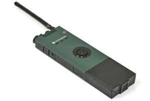
For reception of the ABU, any regular 2-way handheld
police radio could be used, provided that it could be
tuned to the frequency of the miniature transmitter.
A good example is the Telefunken FuG-10 (Teleport VII).
In the Germany, the frequency used by the ABU shown here – 168.360 MHz –
was used by the Bundesgrenzschutz (BSG),
and was known as BOS channel 41.
➤ More information
|
|
|
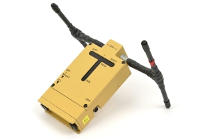
To locate nearby ABU, in particular when it is sending a distress signal,
a small handheld radio direction finder was
used, such as the device shown in the image on the right.
Show here is the M7142 direction finder, which was developed
by the British company Micromill
especially for the BND.
➤ More information
|
|
|
|
The first revision of the ABU was released in 1974, at a time when
Surface Mount Devices (SMD) were not yet widely availble. In fact, only
SMD capacitors and trimmers were available to the designers at the time.
This means that the initial design contained conventional miniature resistors.
|
The image on the right shows the interior of an ABU Rev. 1, with its
transmitter tilted upward by 90°. At the center is a 56.1206 MHz crystal
running in the 3rd overtone (168.360 MHz). In order to save space,
'naked' transistors (without enclosure) are bonded
directly to the PCB. These are the white blobs in the upper half of
the image.
In the lower half of the image, the clock generator is visible.
At the centre is a miniature 4-pin flat IC, similar to the
Siemens TAA131.
It holds three transistors and two resistors. The
TAA131
was released in 1966 for use in hearing aids [a].
|
|
|
|
The rest of the clock generator is built with conventional components.
Like with the transmitter, 'naked' transistors are used to save space.
The wiring between the boards and also the wiring to the antenna, is made
with shellac-coated copper wires (as used in transformers). This
wiring is stiff and fragile, and easily breaks when tilting the boards
too often.
This was improved in Rev.2.
|
|
In 1980, the device and its circuits were completely redesigned with SMD parts,
resulting in the ABU Revision 2 shown here. The enclosure is similar, but is now
made of brushed stainless steel.
|
After removing the rear panel, the
battery holder and a half-circular printed circuit board
(PCB) are exposed. The reverse side of this PCB holds the Quartz Oscillator,
which is used here as the actual transmitter.
As all components are at the other side of the board, we have tilted
it by 90°.
The image on the right shows the tilted board, with a
miniature 56.120 MHz quartz crystal at the centre.
Most of the circuit is built with surface mount components (SMD).
The oscillator comprises two Siemens BFR35A RF transistors (marking GB)
and a varicap diode (marking S1).
|
|
|
|
The varicap is responsible for the Frequency Modulation (FM).
At either end of the board is a thin wire that guides the
output signal to the antenna via spring-loaded contacts.
In this design, the bracelet is used as the antenna.
It consists of two metal parts
that are covered with leather to isolate them from the human body.
The parts are fitted to the case by means of isolated push-pins.
Both ends of the bracelet are folded around these pins.
Two spring-loaded contacts are embedded in the enclosure, and
connect the transmitter to the folded (metal) part of the bracelet.
|
For correct operation of the device it is important that the bracelet
is closed properly, so that the antenna forms a loop. The two orange
parts – one at either side of the crystal – are inductors that extend the
virtual length of the antenna.
Whilst we have tilted the transmitter board by 90°, the clock generator
below it becomes visible, as shown in the image on the right.
The circuit is built
around several integrated ciruits (IC), that are directly bonded to the
PCB. They are covered with a drop of melted plastic to prevent
damage. The types of these ICs are unknown.
|
|
|
|
The clock generator is responsible for the timing of the device, in
particular the 1700 Hz tone and the 1:4 and 1:1 pulse transmission duty
cycles.
It occupies one half of the circular PCB. The other half is
taken by the contact pads of the battery holder and the MODE-selector.
The latter is a rotary switch that selects between 1:4
and 1:1 pulses. It is integrated with the battery holder, whilst its
contacts are printed on the PCB. In the middle position, the device
is switched off.
|
The PCBs are interconnected by means of thin fragile wiring
that easily breaks when bending the PCBs.
The analogue movement is a completely separate device that works
independently from the ABU electronics. 1 To access the movement,
first remove the glass from the front of the device by inserting
a sharp object in the
dent between the window pane and the case.
It is likely that the clockwork can be removed from the case once
the glass is removed, but we haven't tried this as there is no reason
– it works properly –
and we are not watchmakers.
|
|
|
-
Despite the fact that the word 'electronic' is
printed on the dial,
it is an old-school analogue (mechanical) windup movement,
also known as a clockwork, caliber or calibre [3].
It is likely that 'electronic' was printed on the dial
to justify the presence of batteries.
|
|
When we received the ABU, the exterior was in pristine condition
and the device was fully operational. As is always the case with
items of this vintage, the battery compartment shows serious signs
of corrosion caused by leaking batteries. Furthermore, the batteries
that came with the unit were slightly too thick,
as a result of which there is a
gap between the battery lid and the case.
|
A side effect of the above is that when tightening the battery
lid with the screw at the centre,
the PCB bends somewhat (due to the ticker batteries), as
a result of which the 1:1 position of the MODE selector doesn't
always work properly.
The battery compartment was cleaned with isopropyl alcohol (IPA)
and any residual corrosion was carefully removed, while observing
the continuity of the contact pads on the PCB below the battery
holder.
Next, batteries with the correct dimensions
were obtained and fitted. The battery lid
now properly aligns with the case.
|
|
|
A good replacement battery is the SR43 or the 386, (1.55 V,
11.6 × 4.2 mm).
This resolves all problems with respect to the unreliability of the
MODE-selector.
Testing the device with a communication receiver reveals that it
is slightly off-frequency. Instead of the 168.360 MHz printed on
the crystal, it transmits 4 kHz lower at 168.356 MHz. 1
As this can not easily be resolved, we decided to leave it as
it is, and make the necessary correction at the receiver end.
It was noticed that the crown is not firmly attached to the winding
stem. When turning the crown counter clockwise for too long, it will
eventually some off. As a result, it is only possible to turn the crown
clockwise, which makes the hands move counter-clockwise.
In practice, this should not be a problem as it is still possible to
windup the movement and set the correct time.
|
- Battery compartment corroded
- Crown loose
Batteries too thick MODE-selector unreliable (1:1 mode works intermittendly)
|
- Battery compartment cleaned
- Batteries replaced by correct model (SR43)
|
-
Subject to temperature variations.
|
Device Miniature distress transmitter in wristwatch concealment Purpose Tracking of VIPs and intelligence officers, Covert surveillance Model ABU Revision 2 Manufacturer AEG Telefunken Years 1974-1980 Country Germany Users BND, MAD, BfV, BOS Band VHF 155-175 MHz Channels 1 (crystal-operated) Frequency 168.360 MHz 1 Deviation ± 2.8 kHz (F2) Modulation A1 (AM) or F2 (FM) 2 Tone 1700 Hz (F2) Output 12-15 mW Impedance 50Ω Harmonics ≤ -30 dB Antenna Bracelet (covered with leather) Duty cycle 1:4 sec or 1:1 sec Duration > 10 hrs (up to 30 hrs) Power 2.8V (2 × 1.5V button cell) Batteries SR43, see below Current 15 mA (A1), 17 mA (F2) Temperature -20°C to +50°C Storage -40°C to +70°C Dimensions 46 × 41 × 16 mm (HWD) Weight 76 g Quantity 50-100 (est.)
|
-
168.360 MHz was officially assigned to the German
Border Protection Service (BGS)
as channel 41, but is known to have been used by other services as well,
as a BOS inter-services channel.
-
To be determined when ordering.
|
- Mallory 10L124
- Mallory MS41
- Varta 4041
- Varta 7308
- Everready (UCAR) 386
- Everready (UCAR) S41E
- National WL11
- 386
- 301
- SR1142
- SR43
|
749007 Rev. 1 Crypto Museum, Netherlands 809004 Rev. 2 Crypto Museum, Netherlands
|
|
|
|
Any links shown in red are currently unavailable.
If you like the information on this website, why not make a donation?
© Crypto Museum. Created: Saturday 20 December 2025. Last changed: Thursday, 19 February 2026 - 09:56 CET.
|
|

|
|
|