|
|
|
|
|

|
|
Micromill RDF
The device is housed in a standard die-cast aluminium 'Bim Box'
enclosure that has been painted black. It measures 25 × 113 × 51 mm and
weighs just 142 grams.
All connections are at one of the short sides. It is powered externally,
in most cases by the battery of a vehicle.
A suitable antenna should be connected to the SMC connector aside
the screw terminals, either directly or via an
M7014 antenna matching unit.
The M7062 operates on a single crystal controlled channel
between 27 MHz and 175 MHz. 1
The one shown here works at 37.470 MHz (D10).
|
|
|
|
The device was typically placed in a concealed location, like the
motor compartment of a vehicle, so that it could be connected
directly to the 12V car battery. Alternatively it could be
powered via the (optional) M7041 Battery & Power Saving Unit.
It was less suitable for placement under the vehicle,
as it doesn't have a magnet mount and is not waterproof.
It has a built-in accelerometer that detects a running
engine or a moving vehile.
With its 2 Watt output, it was one of the strongest beacons at the time,
with a range of several kilometres.
The one shown here was allegedly used in the late 1980's by the
Dutch Police for tracking the car of a person under surveillance.
|
-
To be specified when ordering.
The device shown here works at 37.470 MHz, which was known
within the law enforcement community at the time as channel D10.
|
The diagram below shows a typical setup with the M7062. In most cases the
device is powered by the battery of the car in which it is hidden.
It can also be powered by the (optional) M7041 Battery & Power Saving Unit.
Any DC voltage between 9V and 15V — typicaly 12V — is acceptable.
The device was typically used in combination with the
M7014 Antenna Matching Unit,
which has a fixed antenna, and is connected to the
antenna output of the M7062 via a supplied coaxial cable.
The M7101 and M7101/10 tracking receivers can interpret the FSK
signals sent by the device.
|
|
|
M7101
|
|
|
The M7062 has two basic modes of operation:
|
In this mode the +12V is connected to the (+VC) terminal and the
0V line is connected to the (0V) terminal. Furthermore, there is
a shorting wire or a switch between the (0V) and the (Slow) terminal.
The device transmits continuously at its basic frequency (f1). Every
two seconds, the frequency shifts up by 500 Hz for 250 ms (f2).
This is a form of Frequency Shift Keying (FSK). It can be used
as the transmitter's ID. When the wire between (0V) and (Slow)
is cut, the pulse rate goes up to 250 ms per 500 ms.
This can be used as an alternative ID (ID2) or to indicate an ALARM state.
Furthermore, the signal is frequency modulated with the signal from
the accelerometer. When received on a SSB or FSK receiver,
this results in a rumbling sound when the engine is started or
the vehicle starts moving.
Note that the accelerometer can only be used in Continuous Mode.
|
In this mode, the +12V supply is connected to the (+VP) terminal.
The device consumes less power, since it only transmits
when the pulse is high. By default there should be a wire or a
switch between the (0V) and the (Slow) terminal, in which case
it transmits for 250 ms every 2 s.
When the wire between (0V) and (Slow) is cut (i.e. switch 'S' is open),
the pulse interval becomes 0.5 s. In this mode, the device is very suitable
for use as an ALARM transmitter. It should be noted however,
that motion detection is not available in this mode.
|
Below is the block diagram of the M7062 when the device is used in
continuous mode. The signal from the oscillator is amplified and
filtered several times, before it is applied to the Power Amplifier (PA),
which delivers approx. 2W. The crystal frequency can be altered somewhat
by two sources: (1) the pulse generator and (2) the accelerometer.
The pulse generator provides a periodic DC signal with a 1:8 or 1:2 duty cycle,
which results in a shift between the fundamental frequency (f1) and
a frequency approx. 500 Hz higher (f2). This can be regarded as the
transmitter's ID.
Changing the pulse rate from 1:8 to 1:2 (by altering an external strap)
can be used as an alternative ID or to indicate an ALARM state.
The accelerometer produces an AC signal that is proportional to its
movement. This signal causes a low-bandwidth frequency modulation of the
crystal.
|
|
The M7063 is housed in a standard Bim-Box™ die-cast aluminium enclosure
that measures 100 × 50 × 25 mm and weighs 142 grams. It consists of a die-cast
shell, covered by matching lid that is held in place by four recessed M3 screws
at the corners. After removing the four screws, the lid can be taken off.
This exposes the interior, as shown in the annotated image above.
|
The device is fully built with analogue electronics and doesn't contain a
single digital component. It comprises an oscillator with a quartz crystal
marked D10T, which refers to the frequency on which it transmits. 1
The crystal is modulated by means of a varicap diode.
The pulse generator provides an short periodic DC pulse that is applied
to the varicap, resulting in a shift in transmission frequency of approx. 500 Hz.
Although this is described in the leaflet [A] and in the manual [B] as
Frequency Modulation, it is actually a form of
Frequency Shift Keying (FSK).
|
|
|
|
The photograph above shows a close-up of the area around the crystal.
Note the BU1771 accelerometer in the foreground.
It is made by Knowles (USA),
and senses vibration (when the engine is running) and motion
(when the car is driving) [a].
The signal from the accelerometer
is amplified and then supplied as an AC signal to the varicap,
resulting in a frequency modulation (FM3) of the crystal. As the bandwidth
is extremely low (500 Hz max.), it is best received in SSB or FSK mode.
|
-
'D' is the band (37 MHz), '10' is the channel withing this band (37.470 MHz),
and 'T' means that the crystal is made for a transmitter.
|
0V Ground (GND) Slow Slow pulses (when connected to 0V) +VP Pulse transmission 1 +VC Continuous transmission 1
|
Device Tracking beacon Purpose Tracking of vehicles, persons or goods Principle RF pulse Model M7062 Manufacturer Micromill Electronics Ltd. Year 1986 Country UK Frequency 27 — 175 MHz 1 Channels 1 (crystal) Modulation FSK (and FM) Deviation 500 Hz (max.) Output 2 W Antenna SMC socket Impedance 50Ω Pulse 1 pulse per 2 sec. (alarm: 2 pulses per sec.) Power +9V to +15V Current 350 mA (@ +12V) Dimensions 25 × 113 × 51 mm (HWD) Weight 142 g Price GBP 425 (1988) [2]
|
-
To be specified when ordering. The device feature here,
transmits at 37.470 MHz.
|
- Anonymous, Micromill M7062 2W RF tracking beacon - THANKS !
Crypto Museum, January 2025.
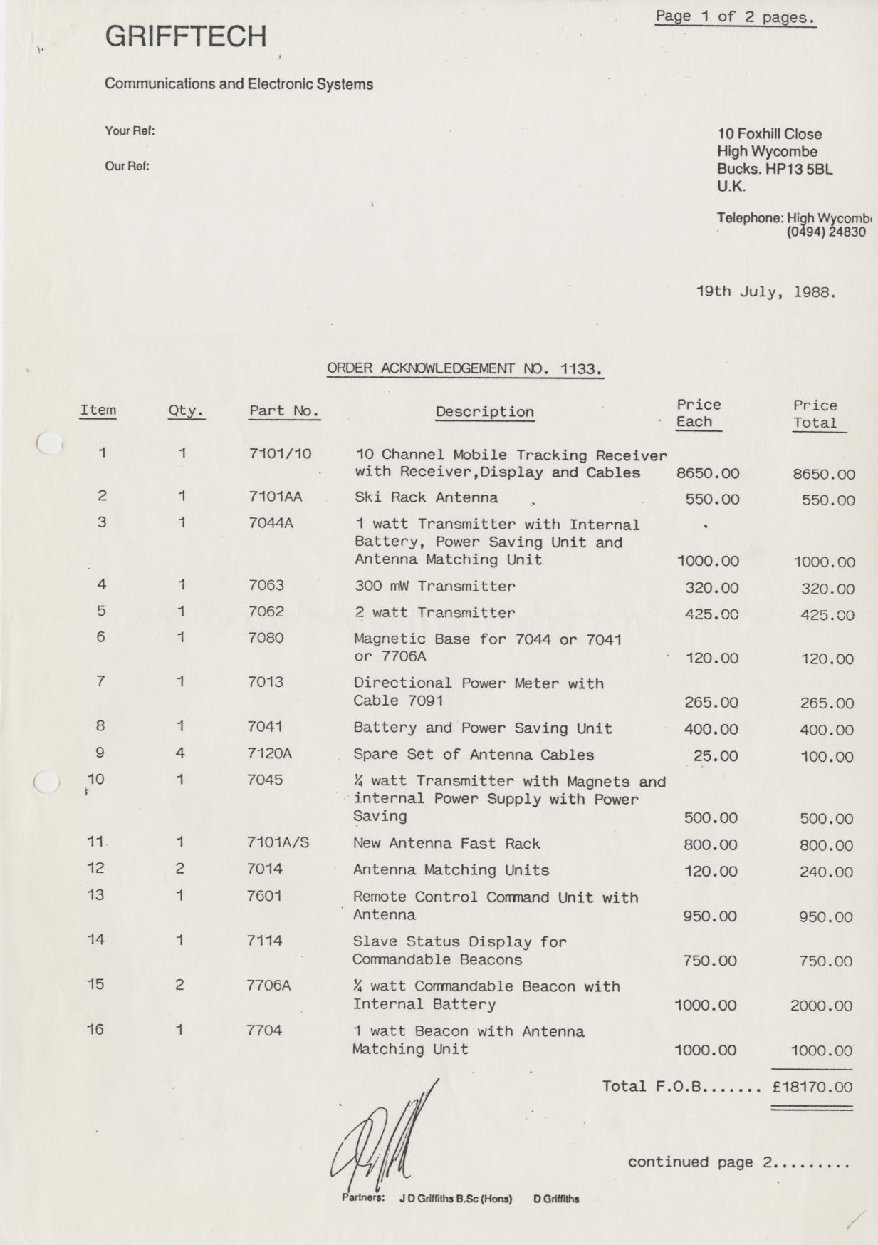
- Grifftech Pricelist 1988
19 July 1988 (Addressee removed).
|
|
|
|
Any links shown in red are currently unavailable.
If you like the information on this website, why not make a donation?
© Crypto Museum. Created: Monday 29 December 2025. Last changed: Saturday, 03 January 2026 - 21:18 CET.
|
 |

|
|
|


