|
|
|
|
|

|
|
Telex EMU Crypto Radio
Message terminal
Telestar 120, 121 and 122, were text terminals,
or correspondence devices, 1
introduced in June 1976 by
AEG Telefunken
in Frankfurt (Germany). The device was
intended for data transmissions (text) via standard voice communications
channels such as analogue telephone lines and HF radio links. The
device was used by the German Police (INPOL),
the BGS 2 and to some extent by
NATO.
Telestar supports data rates between 50 and 9600 baud, and is
teleprinter (telex) compatible. 3
|
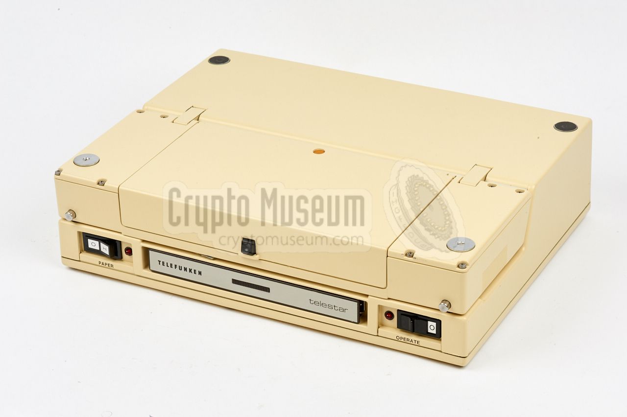
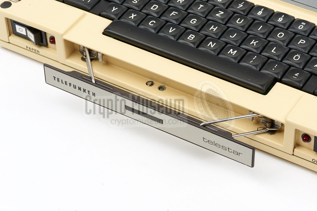
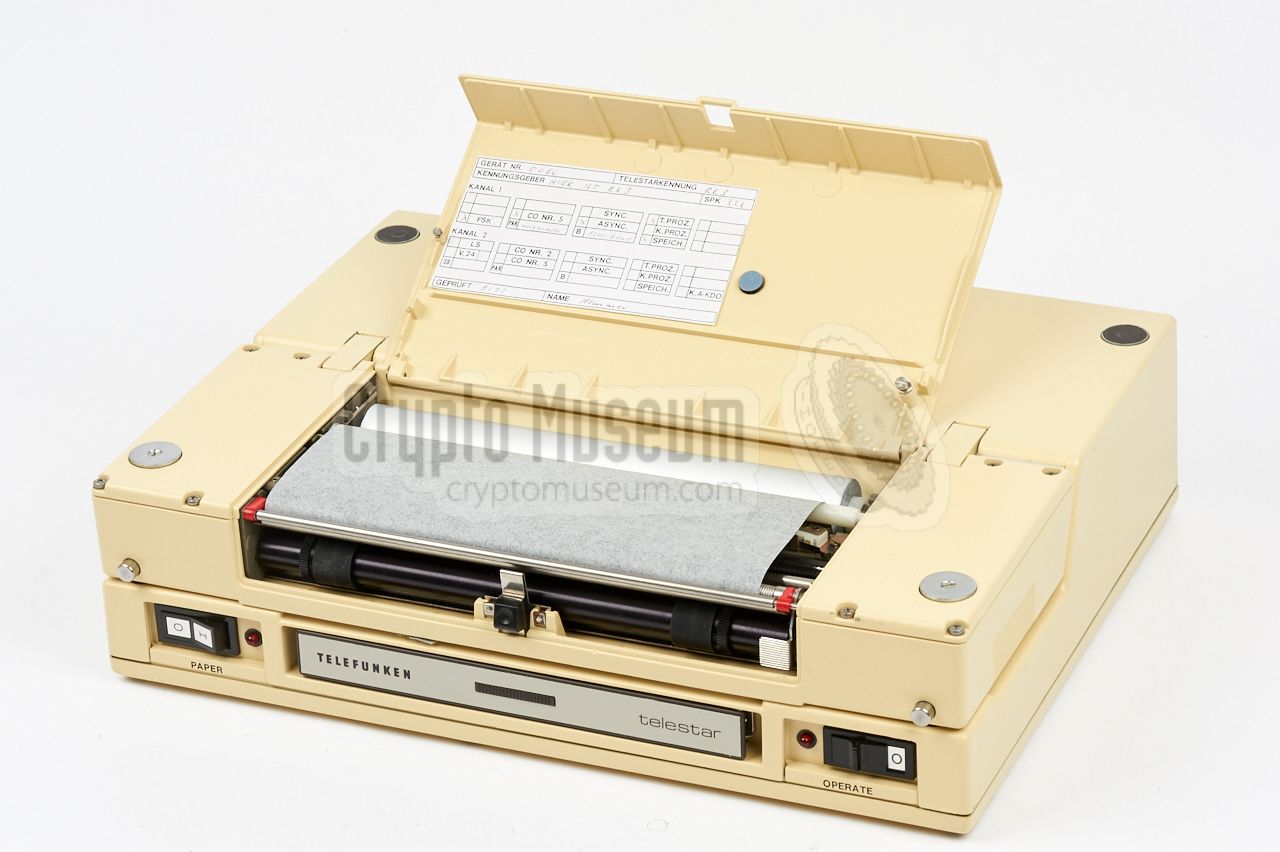
The Telestar terminal is housed in a compact strong aluminium die-cast
enclosure, with a hinged sub-section that contains the thermal printer.
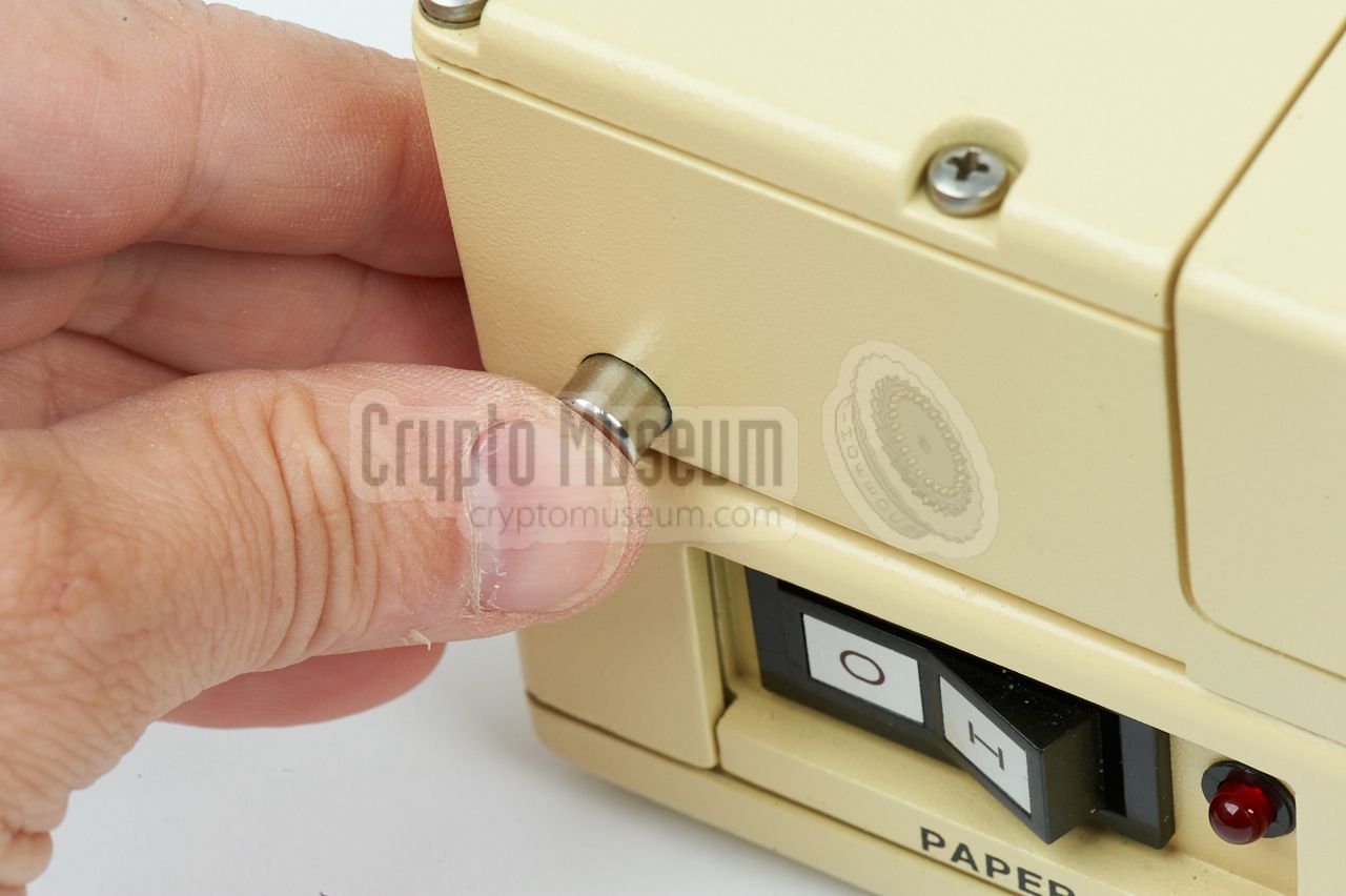
When closed, the device is no bigger than a
standard typewriter. When opened,
the printer is tilted upwards, revealing keyboard
and controls, as shown in the image on the right.
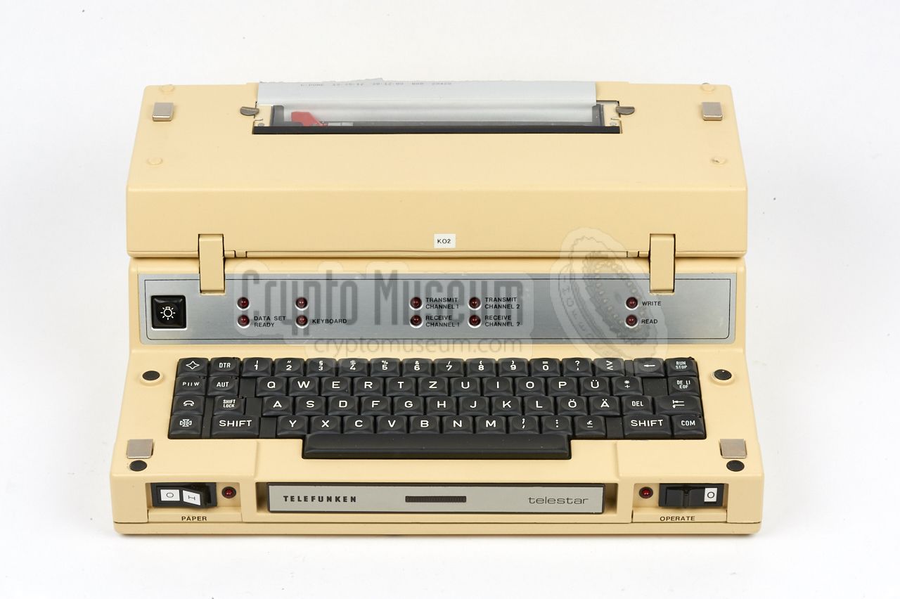
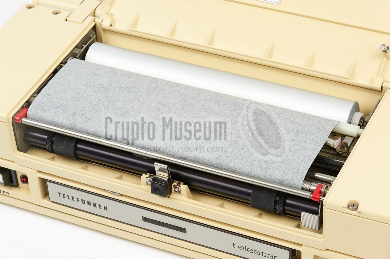
An ergonomic full-size keyboard is used for the input, whilst the output
is printed directly to the thermal printer
that uses a special kind of
A4-wide metalized paper,
similar to the paper used on old weather fax
receivers like the NAGRAFAX.
|
|
|
The name TELESTAR is an acronym for Telefunken Symbol
Transmitter And Receiver. Apparently, public services
were not concerned about privacy at the time.
Although the device was advertised by Telefunken as suitable for secure
transmission [A], the data was not encrypted. In this context, the word
secure was related to data integrety rather than privacy.
The only 'security measure' that was taken, was the
use of ODD PARITY checking and the use of 2 stop bits
in the asynchronous serial data protocol.
Encryption was optionally available by adding an external
TELEKRYPT unit.
Telestar 121 terminals were used by the German Police for online checking of
car registrations, ID checks, criminal records, terrorist activity, human
trafficking, drugs, weapons, etc.
via their INPOL information system.
They were commonly installed inside a police vehicle and were connected
to the existing FuG-7b, FuG-8b
or FuG-9b
VHF/UHF FM radio.
As no data encryption was used, this was definitely a breach of privacy
by today's standards. It should not come as a surprised that much of the
data was intercepted and logged
by the East German security service, the
Stasi [3].
|
 |
-
In press releases, Telefunken referred to the device as
Korrespondenzgerät (correspondence device).
-
BGS = Bundesgrenzschutz (Border Police).
➤ More
-
Teleprinter (telex) compatibility requires the optional
5-level TTY
interface to be installed.
|
All controls of the Telestar terminal are located at the front. When the
device is not in use, they are covered by the thermal printer that can be
tilted forward, acting as a lid over the keyboard. The diagram below shows
the machine ready for use, with the printer/lid on top of the terminal.
The machine can be powered by the AC mains (100-240V) or by an external
DC power source (10-32V) such as the battery of a car. Both can be
connected to the 7-pin Hirschmann socket at the rear.
Suitable cables were usually supplied with the kit.
The Telestar has a regular full-size keyboard with either a German
(QWERTZ) or an international layout (QWERTY).
To the left and right of the keyboard are additional keys that are used
to access special features and commands.
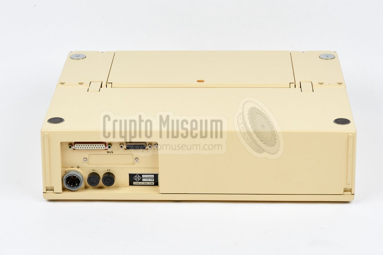
All connections are at a
recessed section of the
rear panel. At the left
is the power socket,
along with the AC and DC fuses (marked F1 and F2
respectively). Above the power socket are the interface sockets, marked
V.24/TTY,
FSK and BUS. All interfaces are optional as
specified below.
|
|
Telestar was available in three versions, each of which has different
features. Connection to the outside world was made via a V.24 or a TTY
interface. Depending on the version and the required options, the price
of a single Telestar unit in 1976 was between DM 12,000 and DM 15,000. 1
|
- Telestar 120
This is the basic model of the Telefunken Telestar that is suitable for
on-line use only. Maximum character processing speed 200 bps
(bits per second, or baud).
- Telestar 121
Similar to the Telestar 120, but with separate transmit and receive
buffer for 2000 (optionally 4000) characters each. Transmission of
messages is under control of the internal microprocessor.
This is the most common Telestar model.
- Telestar 122
Enhanced version that is suitable for online and offline use. The
send and receive buffers are increased to 4000 (optionally 8000) characters
each, and the maximum data transfer speed is 9600 baud. Transmission of
messages is under control of the microprocessor.
|
|
The terminal can be issued with three different interfaces, all of which are
optional. For communication with the outside world, at least one interface
is needed. The Telestar has two communication channels that can be used
simultaneously, identified as Channel 1 and Channel 2.
|
- V.24/TTY
This is an enhanced RS-232 interface that follows the regular V.24 conventions [4].
It can be configured for V.24 use (voltage controlled data signals) or for
TTY teleprinter use. In the latter case, current loops are used for sending
and receiving data. Note that it can be used as either V.24
or TTY, but not both. The required interface is selected with jumper
straps on the interface board. This interface is fitted in most Telestar units.
- FSK
For situations were the Telestar has to be used over radio, an
FSK interface
can be fitted. It has a 15-pin sub-D socket
that carries the transformer-coupled audio input and output signals,
allowing it te be connected directly to the radio. In addition there
are independent relay contacts for controlling the radio's push-to-talk
(PTT) function, and switch between microphone and terminal.
This interface is fitted in many Telestar units.
- BUS
This is a 5-pin sub-D socket that carries direct signals to and from the
microprocessor, bypassing the normal command-controlled system. It allows
the terminal to be used for a variety of applications.
In most Telestar unit, this (optional) interface is not fitted.
|
|
Although the data format of the Telecrypt devices provides some level
of error correction — it uses ODD PARITY checking — the data sent through
its V.24 or TTY interfaces is by no means secure or encrypted.
In a military environment, Telestar units were often used via shortwave
(SW) radio, by connecting it to a 20W
AEG Telefunken SE-6861 manpack radio
or a 100W SE-6863 [A].
|
For secure communication, the Telestar 121 was commonly connected to a
Telefunken TELEKRYPT DAT-812 encryptor, as part of the FFT-6856 installation
shown on the right. This equipment suite was housed in a military
transport case, suitable for mounting in a Jeep, consisting of [B]:
- Telestar 121
- Data encryptor TELEKRYPT-DAT 812
- Forward error corrector FEC-100
- Driver unit STEU-6856
When transmitting messages via a short wave radio channel, the data transfer
rate was limited to 200 baud (in practice typically 50 baud),
whilst A7J (A3J) or F1 modulation was used.
The image on the right shows a complete FFT-6856 system in operation.
The Telestar unit is installed on a telescopic rail at the bottom of the
transport case. At the left – barely visible –
is the SE-6861 transceiver
with its 100W amplifier.
|
|
|
|
The following use of Telestar devices has been confirmed:
|
-
Used for radio data network between the cities in Rheinland-Pfalz and the
regional authorities in Mainz. Possibly also used in other parts of Germany.
➤ Wikipedia
|
During the Cold War, the East German (DDR) intelligence service
Ministerium für Staatssicherheit (MfS),
or Stasi,
was aware of the fact that the German Police used the
Telestar for interrogation of its
INPOL information system.
Stasi Department III subsequently proposed to
develop a system that would be able to decode the
data signals used for INPOL, decode the information that was sent
through INPOL, and store the data for later processing. The system would be
called RASTER IP, and it was anticipated that it would take
three engineers to develop it in nine months time [3].
A total of 23 RASTER IP systems was eventually built;
18 for use in Linie III, and 5 for use by HV A/VIII.
The first research results of RASTER IP were reported
on 25 July 1984. At that point, the system had been running for
24 hours a day for 3 months, providing the Stasi intelligence about:
|
- Monitoring of travel activity
- Location of people
- Confiscated objects
- Travel documents
- Police surveillance
- Drugs
- Weapons
- Forged money
- Ownership
- Criminal networks
- Terrorist networks
- International smuggling
- Dangerous intensive offenders
- International criminals
- Customs supervision
|
|
In January of 1987, the Stasi had become aware of the upcoming
NATO exercise Wintex/Cimex later that year, and had information
that the Telefunken Telestar would be used for the exchange of
information between NATO and the German Police.
Stasi Department III/12 subsequently put in a proposal for
the development of an automated computer-controlled intercept
station, that would be able to catch all data in real-time
and store it for processing at a later moment [3].
|
The Telestar 121 terminal
has an internal microprocessor with suitable software
for entering, storing, correcting, deleting, sending and receiving messages.
The system is controlled by means of commands that are entered via the keyboard.
Each command is started with the COM-button, followed by a single letter
(the actual command) and one or more comma-separated parameters. It
is terminated with the ↵ (ENTER) or EOF key.
➤ Operating instructions
|
|
The following red LEDs are present on the indicator panel:
|
Data Set Ready Ready for receiving a message Keyboard Incomplete message or command entry Transmit channel 1 Transmitting on channel 1 Receive channel 1 Receiving on channel 1 Transmit channel 2 Transmitting on channel 2 Receive channel 2 Receiving on channel 2 Write Paper puncher active (option) Read Paper reader active (option)
|
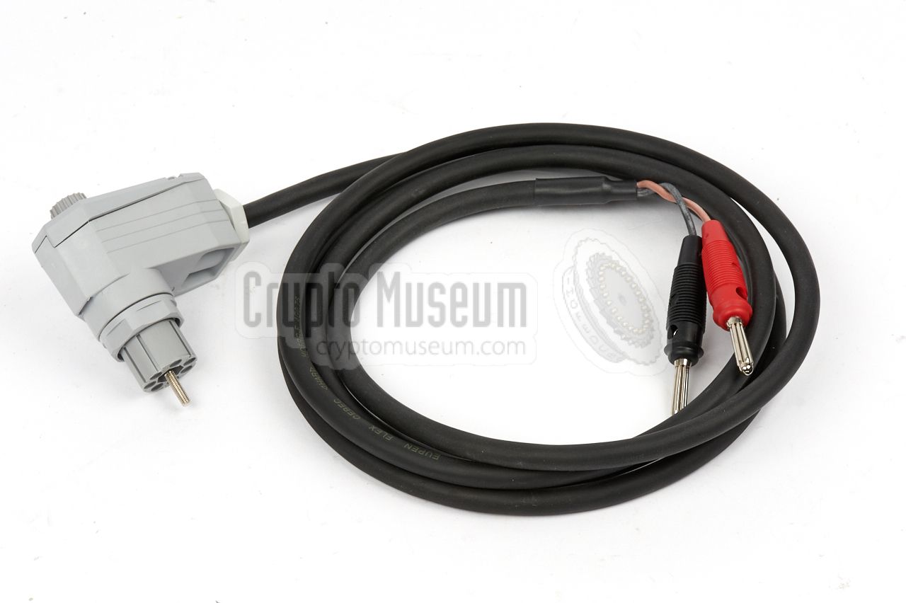
The Telestar has a built-in switched-mode power supply unit (SMPS)
that accepts AC voltages in the range 100 - 240V. The cable shown
in the image on the right is used to connect the terminal to the
mains wall socket.
The three lower pins of the power socket are used for this purpose.
Please refer to the pinout section below for full details about this
socket.
➤ Pinout of the power socket
|
|
|
The Telestar also has a built-in switched-mode power supply unit
(SMPS) that allows the unit to be powered by a DC voltage, such
as the battery of a car, in the range 10 - 32V. The cable shown
in the image on the right is used for this.
The upper two pins of the power socket are used for this purpose.
Please refer to the pinout section below for full details about this
socket.
➤ Pinout of the power socket
|
|
|
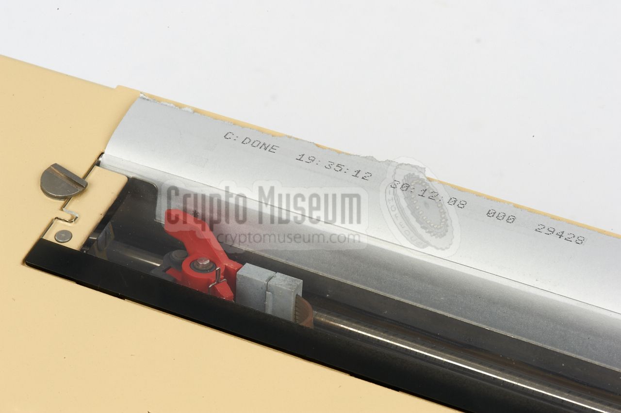
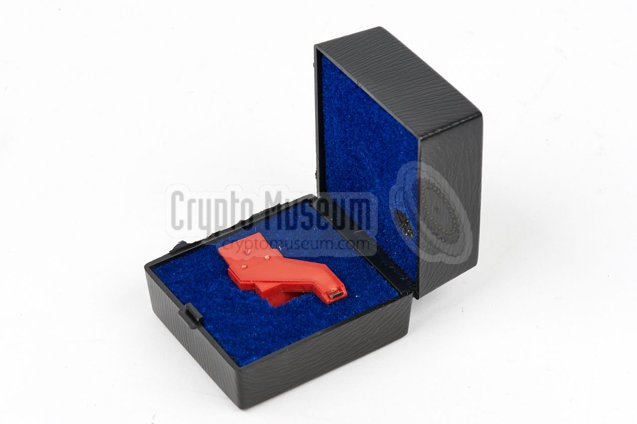
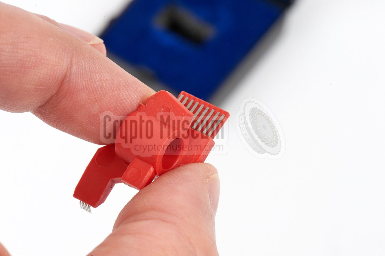
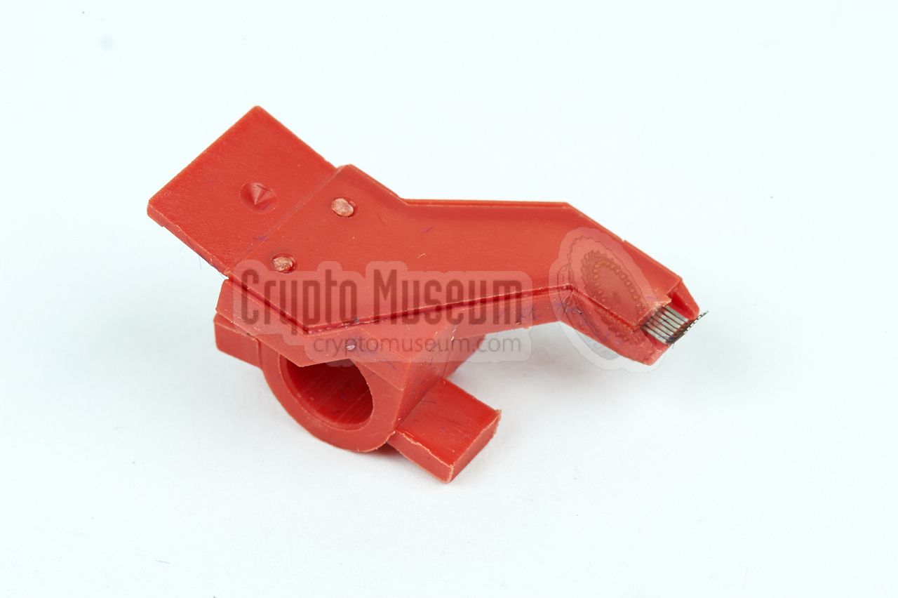
The output produced by the Telestar terminal is printed directly onto
an A4-wide thermal paper sheet, in a 7 x 5 pixel matrix, much like an
ordinary dot-matrix impact printer.
Under normal circumstances, this is completely maintenance-free,
as a thermal printer does not require a
supply of ink or toner. In the rare event that the print head gets
worn-out, it could be replaced by a spare one that was supplied
in a small plastic cassette, as shown on the right.
|
|
|
|
The Telefunken Telestar is extremely well built and is mechanically
very strong. The machine is housed in a heavy die-cast aluminium enclosure
that holds all circuit boards, the power supply unit (PSU) and the printer.
The interior can be accessed by removing 8 screws from the bottom.
|
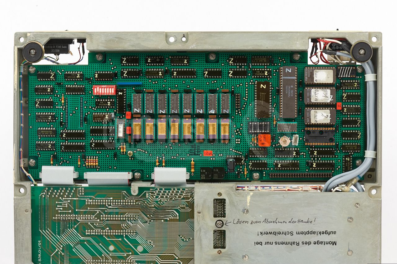
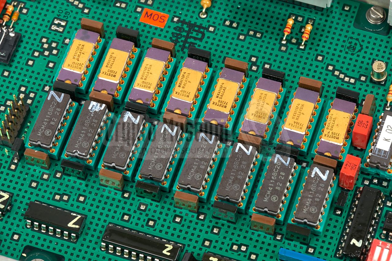
After removing the bottom panel, the large board with the
Central Processing Unit (CPU)
becomes visible. It holds the 8080 processor,
along with RAM memory
and the EPROMs that contain the firmware.
The CPU is connected to the rest of the machine via ribbon cables.
The CPU board occupies about half the available space. The rear half
is taken by the power supply unit (PSU) and the
backplane that holds
the plug-in interface boards at the other side. The top side of the
machine can be removed by removing two screws and loosening a third
one.
|
|
|
|
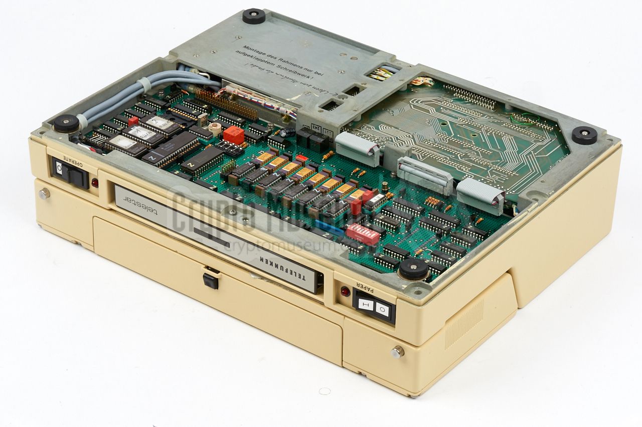
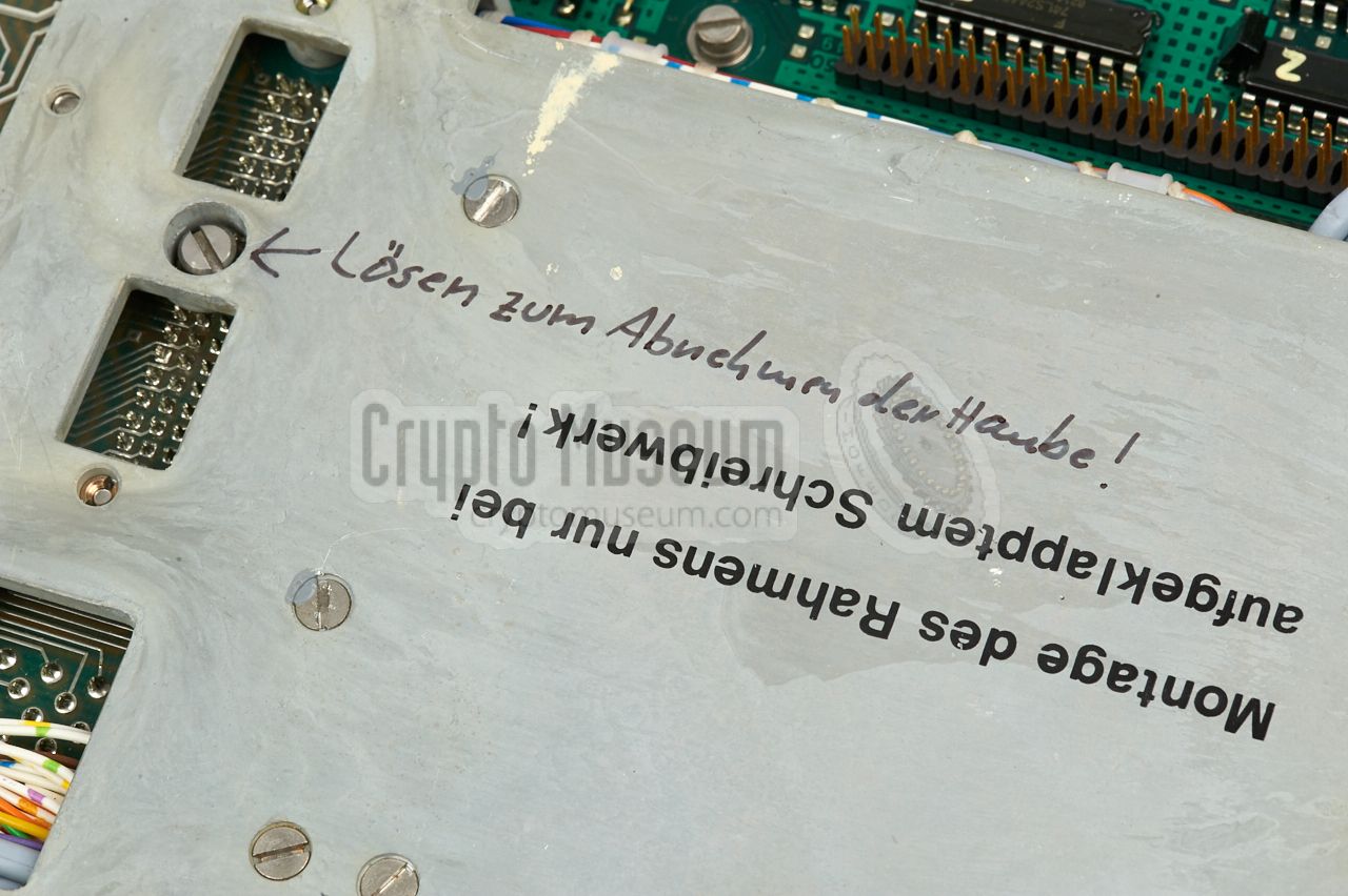
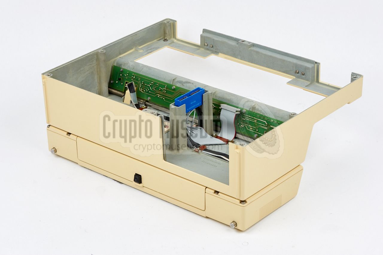
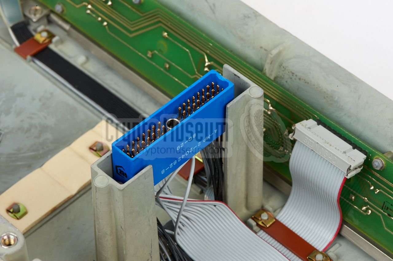
This allows the upper case shell
(which also holds the printer)
to be removed entirely. Note that the
bolt at the center is used
for locking the blue connector
that connects the printer to the CPU.
When removing the upper case shell, some pressure
may be needed to release the connector.
|
The remaining lower half is the frame to which all other parts
are mounted.
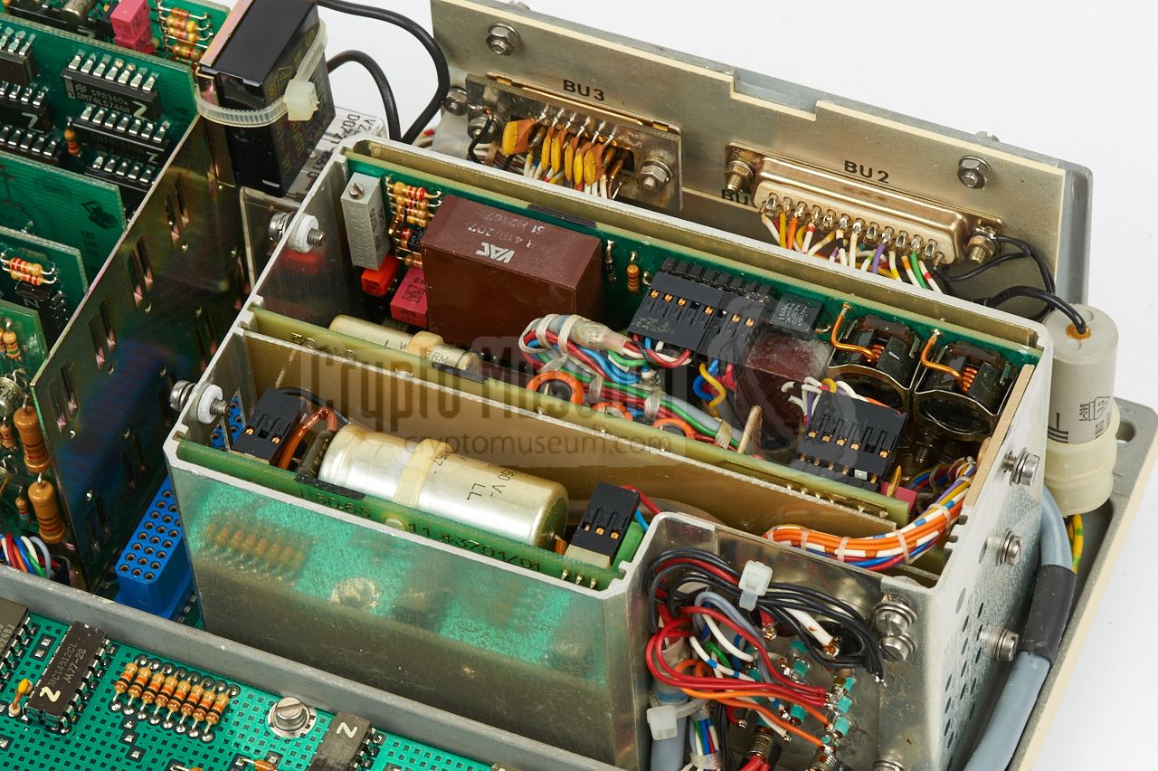
Once the upper case shell is removed, the upper side of the interior
is exposed as shown in the image on the right.
The front half is
taken by the full-size keyboard, which is physically located above the CPU
board.
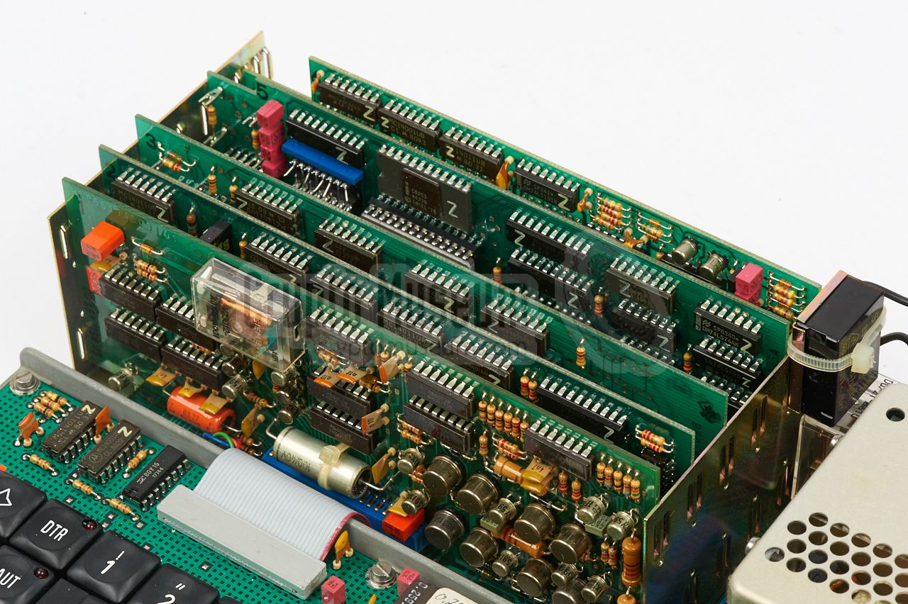
At the rear right is the power supply unit (PSU) that consists of three
PCBs, housed inside a metal enclosure.
The filtered outputs from the PSU
are available at the front right. The mains voltage and the battery
voltage are both routed via the slide switch at the front right corner.
|
|
|
|
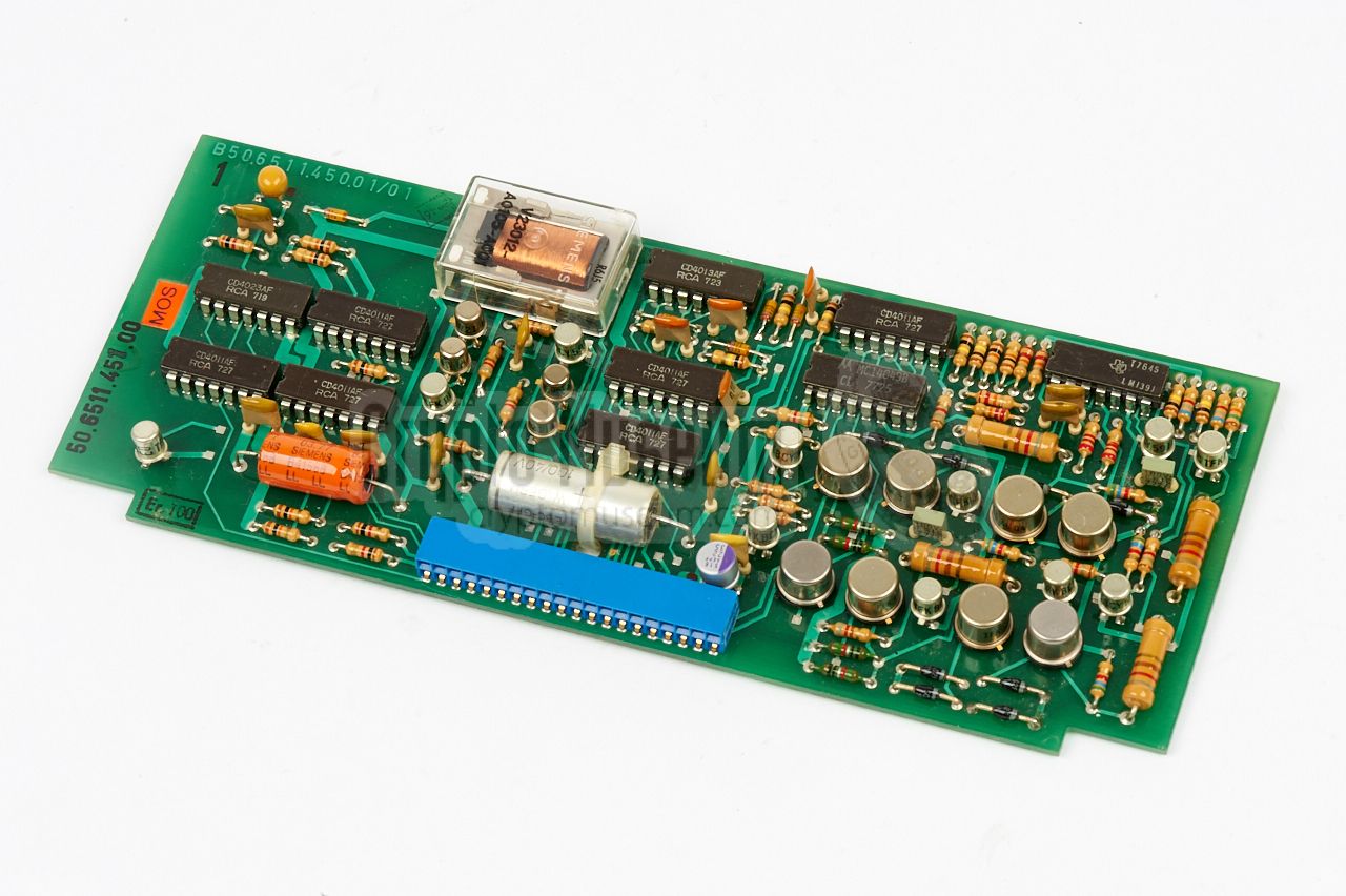
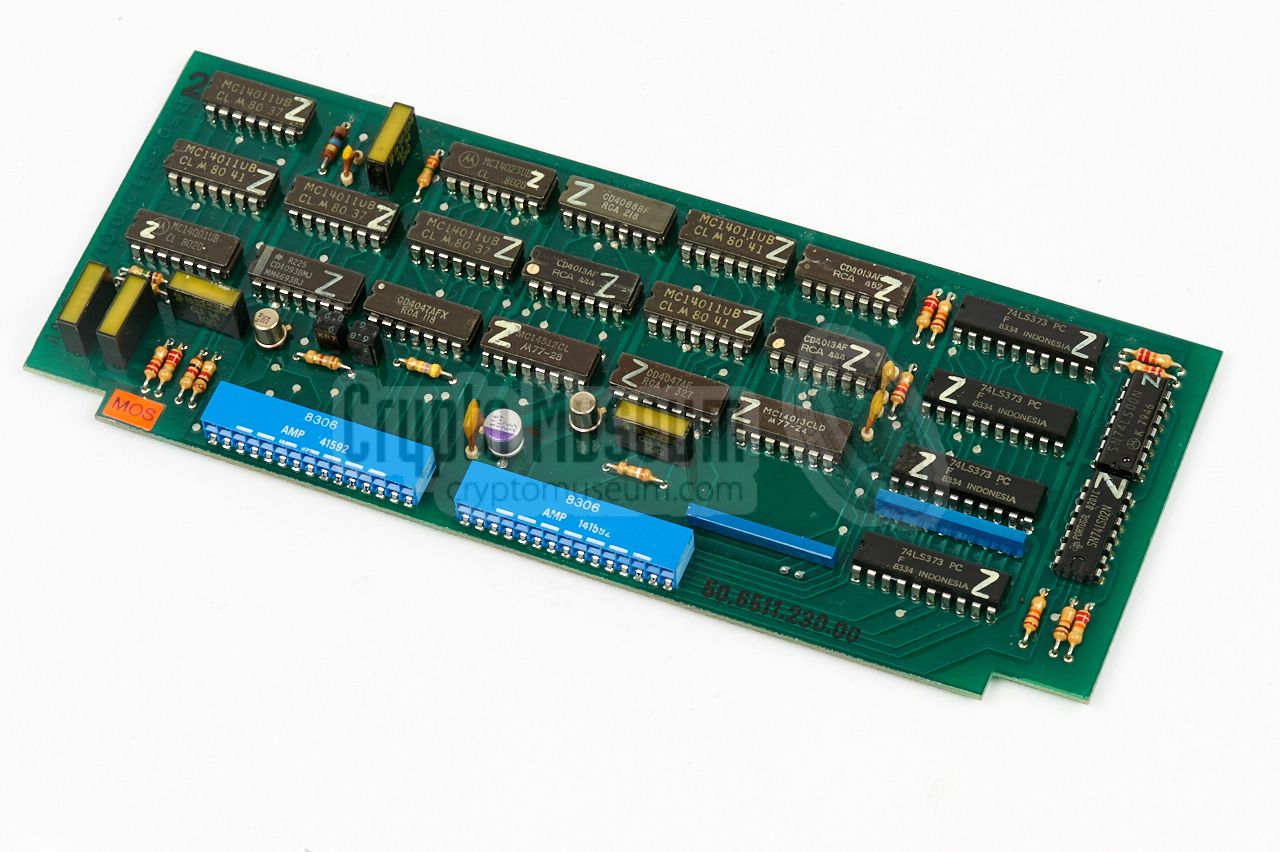
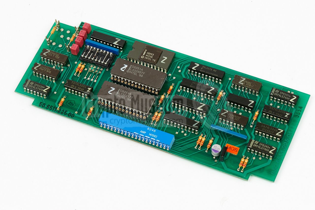
At the left are the various interface boards
which are installed into the sockets of a backplane,
mounted at the bottom of the frame. These
boards contains the drivers for the printer as well as the V.24, TTY
and FSK interfaces and are responsible for connecting the unit to the
outside world.
|
|
Although the Telestar is extremely well-built from first-class
components, chances are high that after 35+ years of storage,
the device no longer works. In most cases this is caused by the
fact that tantalium capacitors are used in the PSU and on all boards,
for stabilising the power lines.
|
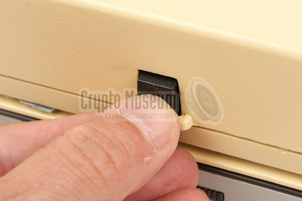
When switching the device ON after so many years of storage,
it will show some activity for one or two seconds and then die.
The power LED (to the left of the power switch) will then be OFF
again. If this is the case, turn the device OFF immediately
in order to prevent further damage.
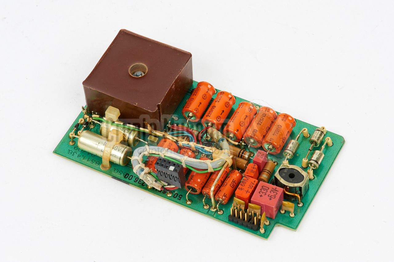
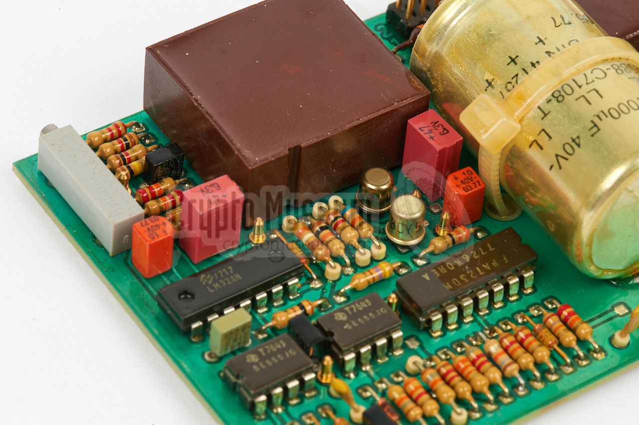
Inside the Telestar is a selection of orange, red and black
tantalium capacitors that may have have deteriorated. The
image on the right shows four such capacitors on one of the
PSU boards. Replacing just a faulty one will generally not
be enough, as the others are also likely to be bad.
|
|
|
|
If only the faulty capacitors are replaced, you will probably
notice that, after switching the device ON, it will work for a
few seconds, until the next tantalium capacitor shorts out.
It is strongly advised to replace all caparactors that are connected
to the various (+) and (-) power rails.
|
If you do so, replace them by fresh new (not new-old-stock)
tantalium capacitors, or by low-ESR ones, such as Panasonic
OS-CON.
The image on the right shows the PSU board after replacing
the capacitors.
Do the same for the CPU board and for all of the interface boards,
re-assemble the machine and then turn it ON again.
If all goes well, the power LED should now stay ON.
When replacing the capacitors, ensure that they are not too high
and that they are mounted close to the board. As some of the boards
are fitted closely together, space between them is limited.
|
|
|
|
It is likely that the above refurbishment is all that is necessary
to give the Telestar a new lease of life. If the machine has seen a
lot of action though, it may also be necessary to replace the print
head, which can be troublesome. Replacement heads were available from
Telefunken at the time.
|
|
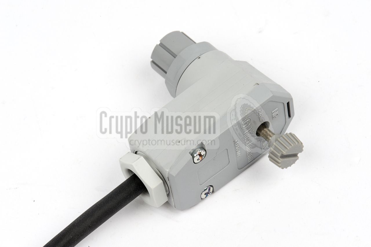
All connections of the Telestar are at the rear panel.
It has a rather awkward socket for connection of the mains (AC) or
battery (DC) power supply, made by Hirschmann. Furthermore there are
sockets for V.24/TTY and FSK equipment.
The diagrams below show the pinout of the sockets, when looking
at the rear side of the device, straight into the sockets.
|
- 100-240V AC
- 100-240V AC
- not connected
- (+) 10-32V DC
- (-) 10-32V DC
- not connected
|
|
|
This is a 25-pin sub-D female socket and can be configured internally for
either V.24 operation or TTY (line current) operation. Note that the
layout for each of these standards is different and that the unused
contacts (-) should not be connected.
|
GND Ground (screen, chassis) TX Transmit data RX Receive data RTS Request to Send CTS Clear to Send DSR Data Set Ready GND Signal ground DCD Data Carrier Detect (signal strength) - -
- -
- -
- -
- -
- -
TXC Transmit Clock (rising edge) - -
RXC Receive Clock (falling edge) - -
CTL Control channel TX on DTR Data Terminal Ready - -
RI Ring Indicate (incoming call) HS High speed TXC- Transmit Clock (falling edge) - -
|
|
- -
- -
- -
RTS Request to Send (input) CTS Clear to Send (output) - -
GND Ground (0V) - -
- -
TXA Line current TX (+) TXB Line current TX (-) RXA Line current RX (+) RXB Line current RX (-) RRA Line current RX Request (+) [option] - -
RRB Line current RX Request (-) [option] - -
- -
- -
- -
- -
- -
- -
- -
- -
|
|
|
This is a 15-pin sub-D male socket that holds all signals to and
from the radio. It also controls the PTT and microphone lines of
the radio. Check out the diagram for connection to the FuG-8b
to see how the audio lines are interfaced by means of transformers.
|
- FSK in A
- FSK out A
- Mic switch 1 n.c.
- PTT
- not connected
- FSK out B
- not connected
- not connected
- FSK in B
- Mic switch 1 common
- Mic switch 1 n.o.
- PTT
- Mic switch 2 n.c.
- Mic switch 2 common
|
|
-
n.o. = normally opened
-
n.c. = normally closed
|
The diagram below shows how the Telestar terminal was connected to a
German FuG-7b, FuG-8b
or FuG-9b VHF/UHF FM radio. In this diagram, the
terminal is linked directly to the radio, via the FSK interface,
without the addition of an encryption device such as the TELEKRYPT.
|
|
FSK
|
|
Frequency Shift Keying
System whereby two different audio tones are used to transmit
the digital levels 0 and 1 of a digital data stream.
Also known as Audio Frequency Shift Keying (AFSK).
|
|
INPOL
|
|
Informationssystem Polizei
Nation-wide information system, used by the German Police and the
Federal Criminal Investigation Units, for storing and interrogating
sensitive information about criminals, criminal offences, terrorist
activities, personal data, human trafficking, smuggling, drugs,
etc. The system entered service in November 1972 and was improved and
extended in the following years.
|
|
RASTER IP
|
|
CODEWORD
Stasi codeword for an automated system that was developed to intercept,
store and process data from the West-German INPOL information
system, that was acquired via
radio interception.
The codeword RASTER IP was also used for the intelligence
derived from the intercepts.
|
|
TELESTAR
|
|
TELEfunken Symbol Transmitter And Receiver
|
Crypto Museum are currently looking for the original service manual and
the circuit diagrams of the Telestar 121. If you have any information about
this device, which is not available in the Documents section below,
please contact us.
|
Device Teletypewriter Purpose Mobile messaging by emergency services Model 120, 121, 122 Year 1976 Manufacturer Telefunken Frankfurt (Germany) Users German emergency services, INPOL, BGS, Bundeswehr, NATO Standard 1 ITA2 (Baudot) 7O2, 1 start bit, 7 data bits, 1 parity bit, 2 stop bits
ITA5 (ASCII) 5N2, 1 start bit, 5 data bits, no parity, 2 stop bits Speed 50, 200, 600, 1200, 2400, 4800 bps (simplex: 9600 bps) Paper Metallized paper, 210 mm wide (A4), 23 metres long Printer Thermal, 75 cps (characters per second) - effectively 35 cps Resolution 5 x 7 dot matrix TX buffer 2000 characters (optional 4000) 2 RX buffer 2000 characters (optional 4000) 2 Mains 100 - 240V AC (automatic) Battery 10 - 32V DC (automatic) Consumption 20-28W (DC), 28-37W (AC) Temperature 0°C to +55°C (optional: -10°C) Storage -40°C to +70°C Dimensions 273 × 291 × 98 mm (147 mm when opened) Weight 7.5 kg
|
-
Option: Either ASCII or Baudot. User-specific standards available on request.
-
Telestar 121 and 122 only.
|
- Klaus Paffenholz, Telefunken Telestar 121 - THANKS !
Received July 2017.
- Pionier, Telestar - neue Korrespondenzgeräte von AEG-Telefunken
Pionier (magazine), Volume 50, Issue 1, January 1977. Page 8-9.
Retrieved July 2017 via HamFu (Switzerland).
- Jörg Drobick, Informationsgewinnung ... Telestar
SAS und Chiffrierdienst (website), July 2017, February 2024.
- Wikipedia, RS-232
Retrieved July 2017.
- Wikipedia (Germany), Katastrophenschutz
Retrieved AUgust 2017.
|
|
|
|
Any links shown in red are currently unavailable.
If you like the information on this website, why not make a donation?
© Crypto Museum. Created: Thursday 20 July 2017. Last changed: Tuesday, 09 July 2024 - 12:27 CET.
|
|

|
|
|
|