|
|
|
|
|

|
|
← SP-20 ← Germany SBO SF KS-30 → S-6800 →
The device is housed in a metal enclosure that has the same
external dimensions as the other parts of the SP-20.
As digital PLL synthesizers 1 did not yet exist at the time,
a collection of 72 carefully picked (different) crystals –
was used to obtain the desired frequency by way of mixing.
This was done by organising the crystals in two matrices of 36 crystals
each. A single crystal in each matrix was selected by two selectors
with 6 positions each (6 x 6 = 36). For this, three rotary selectors
are available at the front panel, whilst a push-button and 6 LEDs act as
the fourth one.
|
|
|
Only a small number of STEU-6800 units were ever build, probably no more
that 10 units or so.
Operating the device must have been very complicated. As the selectors
at the font panel have a limited range (1-6 rather than 0-9), it is not
possible to enter the desired frequency directly. Instead, it was necessary
to use large conversion tables to select any of the 1296 channels.
As a result, the device had a short operational life and was abandoned
after the first field tests [2].
It was decided to use the S-6800 transmitter
with individual crystals
(installed in the socket on its front panel) rather than using the analogue
synthesizer. In the late 1970s, when the digital PLL had become
available, the the crystals were eventually replaced by the
KS-30 digital synthesizer.
We are indebted to Jim Meyer and Fritz Arends for providing
backgrounds on the STE-6800, such as the device's name, the intended purpose and
its development history. Fritz Arends
was one of the key developers
of the SP-20
at Telefunken
in Ulm at the time. He was also responsible for the
S-6800 transmitter.
Jim is a former user, who has helped us on
numerous occasions before [1].
|
 |
-
The first papers about a digital PLL frequency synthesizer appeared
around 1974. ➤ Wikipedia
|
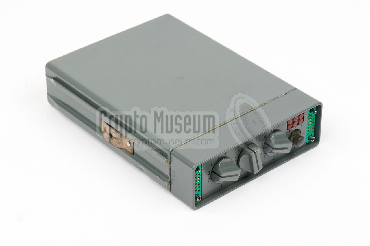
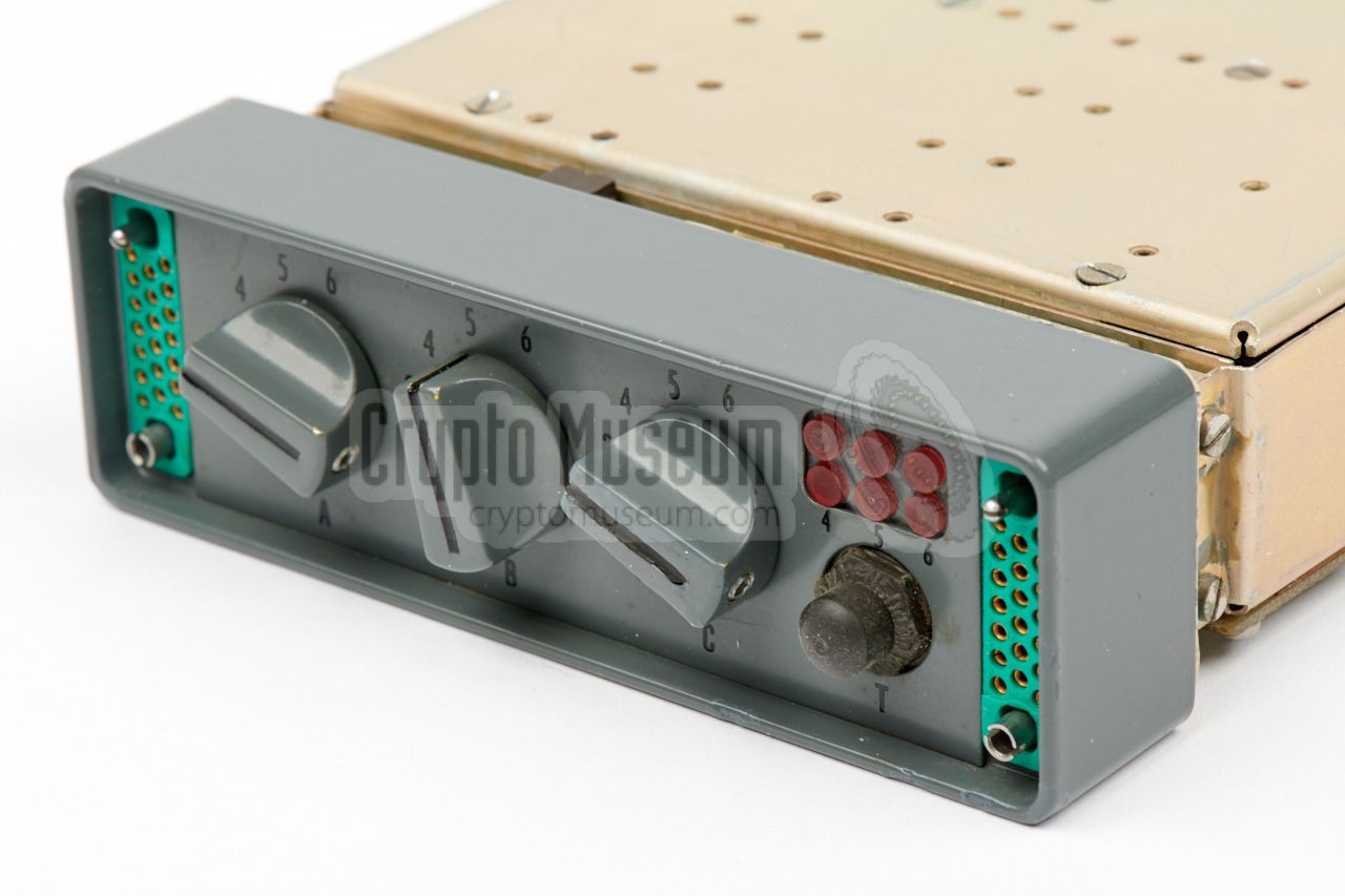
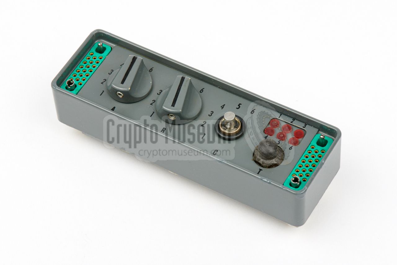
All controls and connections of the STEU-6800 are at the
front panel.
At the left is a 20-pin socket for connection of an external
keyer,
or burst encoder,
such as the Speicher or the
MMP.
At the right is a similar
20-pin socket for connection to the S-6800 transmitter.
12V DC power is provided by the transmitter via this socket.
When connected, the keyer takes over the function of the transmitter's
morse key. When the keyer is not connected, it is replaced
by a terminator.
There are four selectors at the front panel, each with a setting between
1 and 6. Three of these are rotary selectors, whilst the fourth one consists
of a push-button and 6 indicator lamps. The first two selectors (A and B)
control one bank of 36 crystals (6 x 6), whilst the remaining two (C and T)
control the other bank of 36 crystals.
This gives a total of 36 x 36 = 1296 channels.
Note that the channel selectors have no direct relation to the
actual transmission frequency.
|
The diagram below shows how the circuit works, and how the two banks
of 36 crystals each, are mixed to obtain the desired frequency. At the top
left is a crystal oscillator with a fixed frequency of 2.6 MHz. It is the
starting point of the frequency synthesis, and is also used for producing
a high-speed morse code
signal, by causing small frequency shifts (Frequency Shift Keying or FSK).
After amplification, the 2.6 MHz signal is mixed with the frequency from
a single crystal of the rightmost crystal bank, that lies in the 27.375 to
27.651 MHz range. It causes small changes in the output frequency.
The output of the first mixer is amplified and mixed with the frequency of
a single crystal from the leftmost crystal bank, which lies in the 32.400
to 53.000 MHz range. This bank causes the bigger variation in the output
frequency, which will eventually be ~ 2 - 24 MHz.
The diagram above shows how the two crystal banks work. The 6 lines
from two of the front panel selectors (1-6) are used to select a row
and a column of an electronic matrix. As a result, one of the 36
crystals is selected. In practice, the crystals of each matrix
are organised in 6 banks of 6 crystals each. The banks are connected in
parallel and the row signal is used to select the appropriate bank,
whilst the column signal is used to select one of the 6 crystals in that bank.
|
|
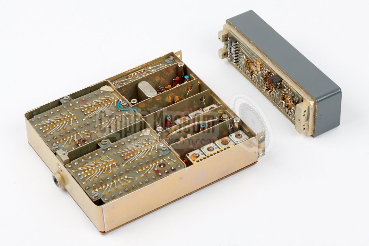
Like most other components of the SP-20 product line, the interior
of the device can be accessed simply by removing a single recessed screw
from the centre of the rear side, and
sliding off the case shell.
Note that it is a tight fit that may bind, so be careful not
to damage any internal parts.
|
Inside the unit is a rectangular frame
with a large carrier board at the bottom.
All internal circuits are mounted and connected to this board. This
board is protected against short-circuits with the case shell, by means of a
thin pertinax sheet.
The top of the compartmented frame is
shielded by a metal panel that is held
in place by three recessed screws. After removing the shield, the individual
circuits of the unit are exposed. The interior can roughly be divided into two
sections: the rear half that holds two large crystal banks, and the front half
with mixers and oscillators.
|
|
|
|
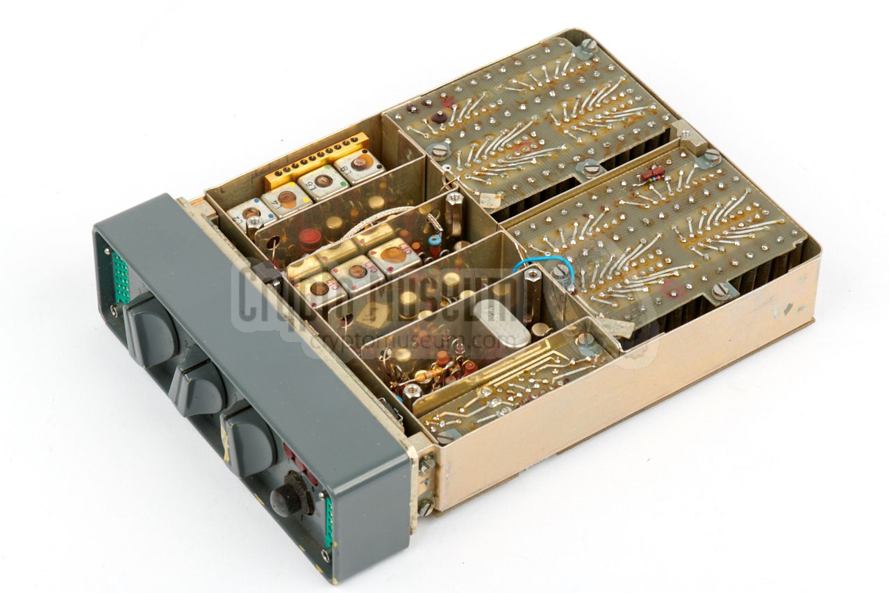
The image above shows a top view of the frame, with the two crystal banks
removed from their sockets. At the front half, the signal goes from right to
left. At the far right are the keyer circuit and the 2.6 MHz oscillator.
Next are the mixers that combine the signals from the crystal banks.
|
Each mixer consists of a crystal oscillator, an amplifier, the necessary
filters and a finally the actual mixer circuit. Each crystal oscillator is
connected to a single crystal from its crystal bank, as selected by the
front panel controls.
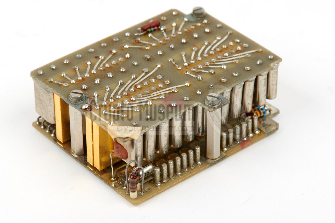
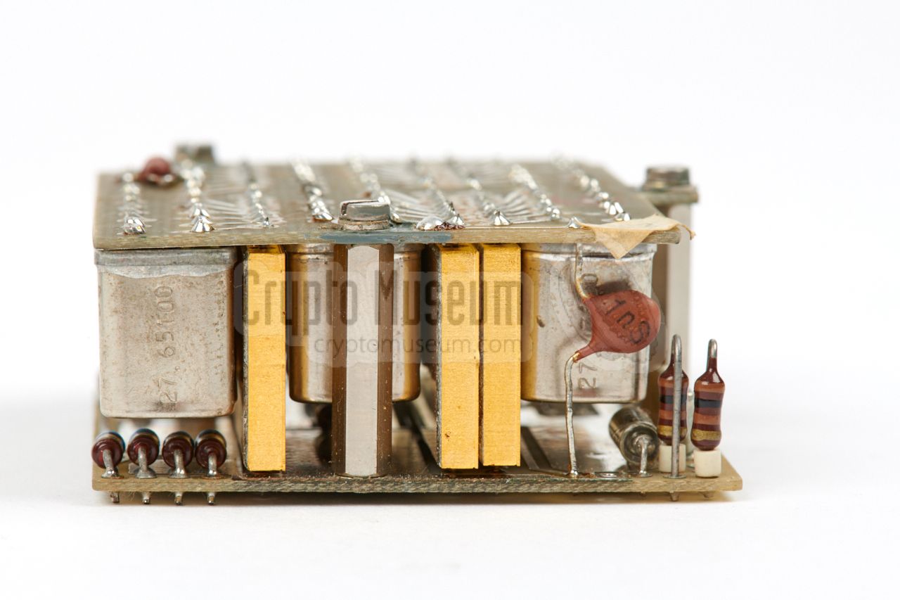
The image on the right shows a close-up of the rightmost crystal bank. At
the front right are the 13 pins of the socket through which it connects
to the carrier board at the bottom.
The crystals are arranged in 6 blocks of 6 crystals each,
and one side of each crystal is connected to ground. The other side
is fed to an electronic matrix.
|
|
|
|
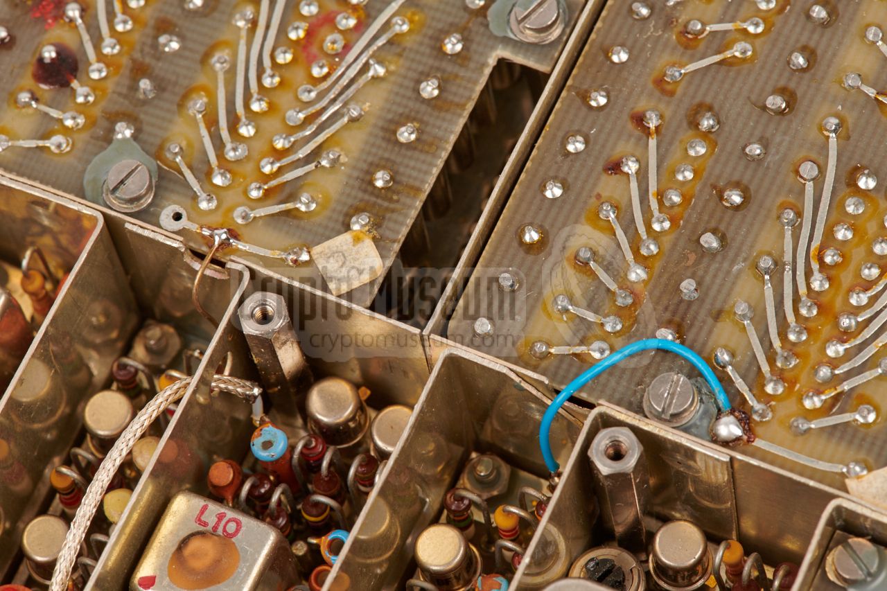
Each block of 6 crystals has its own matrix switch, which is housed in
a rectangular gold-plated enclosure that has 10 pins at either side.
The entire crystal bank is constructed as a so-called
cordwood structure,
with the components mounted between two
parallel printed circuit boards.
|
The cordwood construction method 1 was a very popular space saver
in the 1960s, but makes it very difficult to service or repair
a broken unit.
At the far left of the frame, is a 4-stage output filter, followed
by an amplifier that delivers an output power of approx. 20 mW, which should
be sufficient to drive the transmitter.
The output amplifier is constructed as a minature circuit and - like the
crystal banks - it is housed in a gold-plated enclosure of which the
10 contacts at the top are unused. The image on the right shows the
output amplifier, located behind the filters.
|
|
|
|
The overall mechanical and electronic construction of the device is
excellent, with just a few modificiations in the circuits. The modular crystal
banks are well-constructed, but it must have been a nightmare to calculate
the correct frequencies for each of the 72 individual crystals.
|
The control panel on the other hand, seems to be overly complicated.
It is attached to the main carrier board by means of a 32-pin header
at the bottom. It holds the sockets for connection of the external keyer
and the S-6800 transmitter, plus the four selectors for the two crystal banks.
In principle, the front panel should have had four rotary selectors:
two for each crystal bank, but it was decided to replace the rightmost
selector by a push-button and 6 lamps, probably due to lack of space.
As a result, a complex circuit with three ICs had to be developed
to do the same.
|
|
|
|
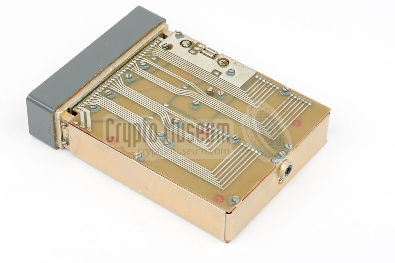
The image above shows the front panel detached from the frame,
with its PCB facing upwards. Here we see the contacts of the three rotary
dials, and the ICs that are used for the push-button selection. One IC
(towards the right) is sticking out of the PCB. The one at the far left has
been damaged – probably due to falling – and had to be replaced.
At the bottom is the 32-pin header.
|
|
When we received the synthesizer featured on this page, it was assumed that
it was probably some kind of
burst encoder, similar to the
so-called Speicher morse keyer.
After all, it was identified as such in Louis Meulstee's
excellent book Wireless for the Warrior, Volume 4 [3].
|
At the first inspection we noticed that the knob of the rightmost rotary
selector at the front panel had been damaged, probably from falling. We will
deal with this part later. After opening the unit however, we noticed that
it was neither a high-speed keyer, nor a memory (German: Speicher), but a full
blown analogue synthesizer.
This was a great discovery, as it was hitherto not publicly known that
an analogue synthesizer for the SP-20 had ever existed. It was a bit worrying
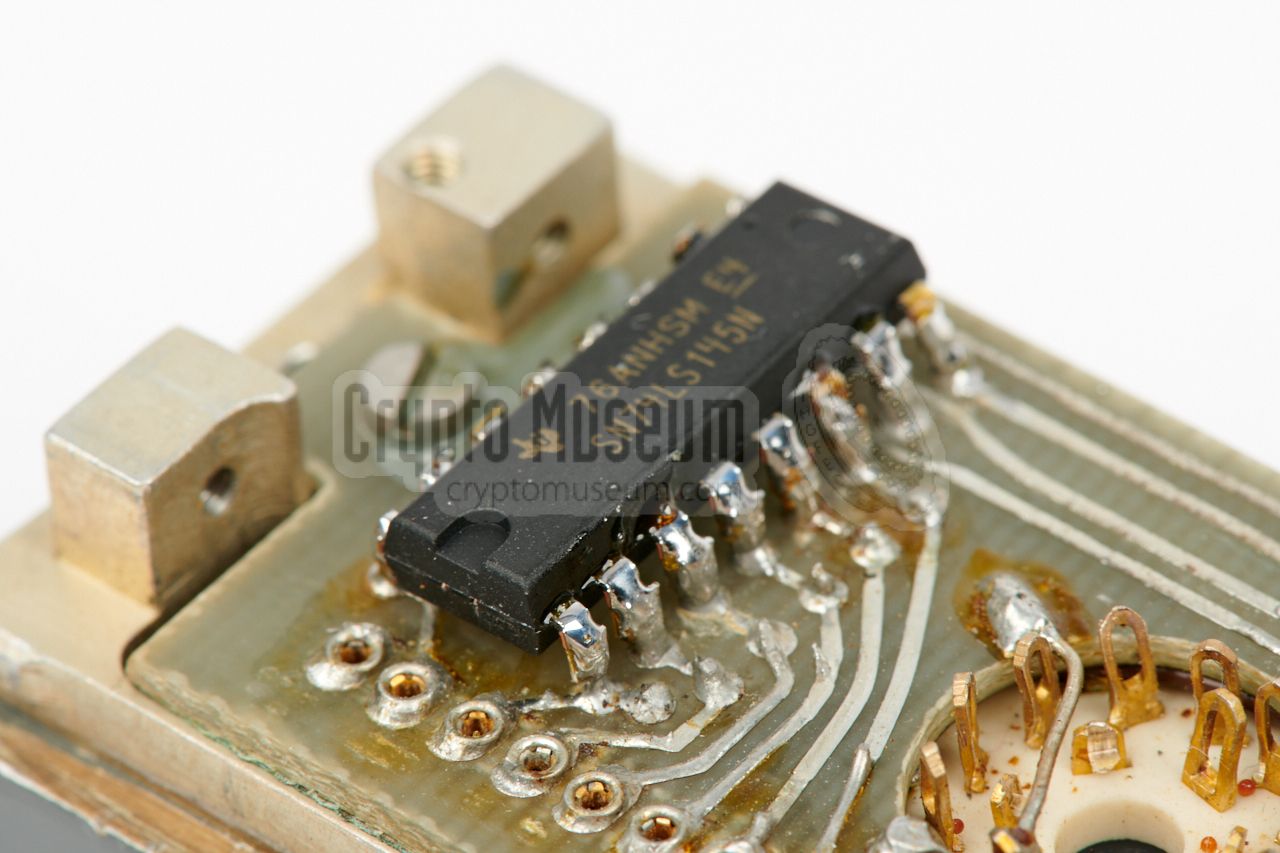
however, that one of the ICs on the front panel circuit board
appeared to be damaged badly.
|
|
|
|
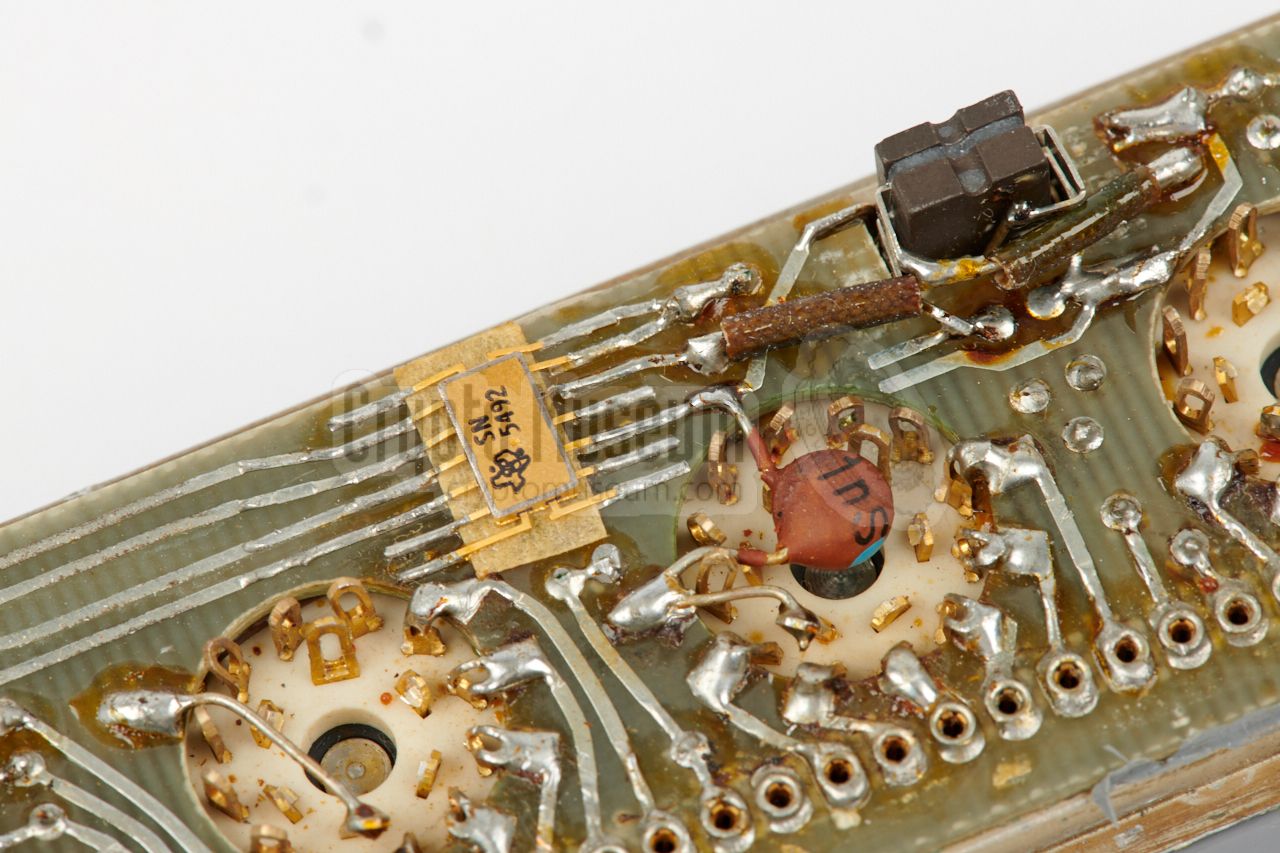
The image above shows the damaged IC, of which the bare chip has become visible.
This IC is part of the front panel push-button selector
(with the 6 red indicator lamps), and controls the least-significant unit
of the channel selection.
Luckily, based on the wiring pattern of the PCB and the surrounding
components, we were able to deduce that it was an SN74145 decoder/driver [4].
|
As it appeared to be very difficult to remove the PCB from the front
panel, the replacement IC was soldered onto the remains of the old
one's legs. It had to be as close to the PCB as possible, as otherwise
it wouldn't fit in the available space.
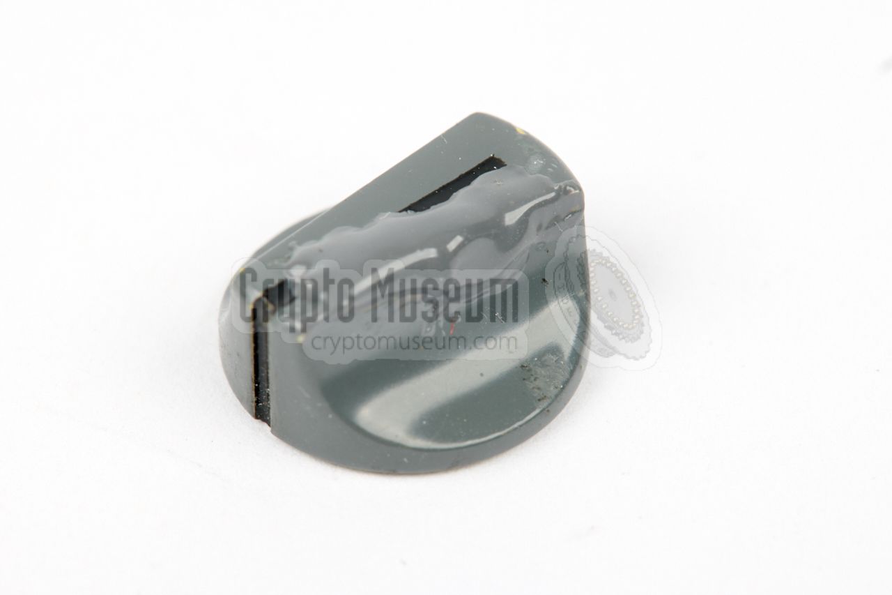
In the meantime, the damaged edges of the front panel — probably also
caused by falling — were restored and painted, just like the knob
of the rightmost rotary selector, that had completely lost its original
shape. With some metal/epoxy filler and a lot of patience, the knob got
most of its former glory back, as shown in this picture.
|
|
|
Once the cosmetic issues were solved, it was time to reassemble the device
and give it a try. This was done by connecting it to the
S-6800 transmitter,
using the interconnection cable of the later KS-30 synthesizer.
It was assumed that the latter had the same wiring as the STEU-6800.
This assumption turned out
to be correct, and the STEU-6800 showed a sign of live immediately after
a 12V power source was connected to the transmitter. The first of the six
red LEDs (1) became lit.
Further tests showed that it will be difficult to determine how the channels
are assigned, partly because some of the crystals are no longer working
(like the other damages, probably caused by falling), and partly because
of the poor suppression of spurious signals generated by the device.
The following items had to be restored:
|
- Knob of rightmost rotary selector damaged
- Damaged IC on the front panel PCB
- Damaged paint on the edges of the front panel
|
|
The table below shows the pinout of the leftmost socket as seen from the
front of the synthesizer. This socket is used for connection of peripherals,
such as a morse key or a high speed morse burst transmitter, like the
the Speicher
or the MMP. If the socket is unused,
a terminator
should be installed.
|
- n.c.
- Loop 1 1
- Loop 1 1
- n.c.
- GND
- Loop1 1
- GND
- Loop 2 1
- Loop 2 1
- 10...15V
- n.c.
- Loop 2 1
- 10...15V
- Tastung 3
- n.c.
- n.c.
- Auftastung 2
- Tastung 3
- n.c.
- Auftastung 2
|
|
|
The table below shows the pinout of the rightmost socket as seen from the front
of the synthesizer. This socket is used for connection to the transmitter.
The loop wires shown in the drawing reflect the internal
wiring of the socket, just like in the later KS-30 synthesizer.
|
- HF
- Loop 1 1
- Loop 1 1
- HF
- GND
- Loop 1 1
- GND
- Loop 2 1
- Loop 2 1
- 10...15V
- n.c.
- Loop 2 1
- 10...15V
- n.c.
- GND
- n.c.
- Auftastung 2
- n.c.
- n.c.
- Auftastung 2
|
|
-
These lines are 'cold' links between the left and right sockets.
They run straight from the peripheral to the transmitter and
are not connected to anything inside the synthesizer.
-
In A1 mode, Auftastung is used for the connection of a morse
key or a medium-speed burst encoder. The line Tastung should
be grounded, by means of a terminator plug.
-
In F1 mode, Auftastung is used to enable the transmitter, whilst
Tastung is used for keying the data with a high-speed burst
encoder. The line Tastung is only available on the leftmost socket.
|
|
|
Connecting to the transmitter
|
|
|
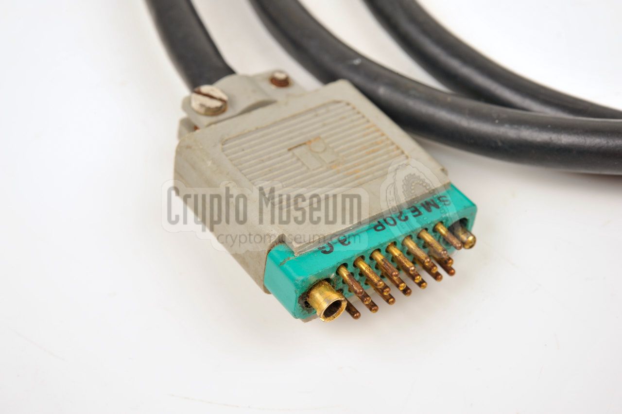
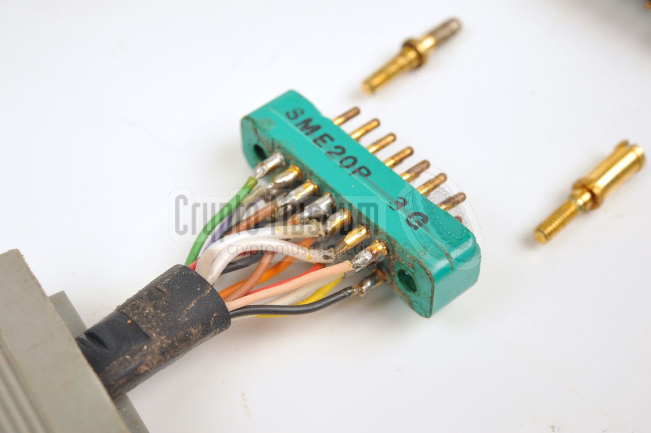
For connection between synthesizer and transmitter, a 16-way shielded
cable is used, with a 20-pin SME20P connector 1 at either end.
Two pins of this connector are used for connection of the shield and
two other pins remain unconnected. The wiring 2 of this connector, when
looking into the female sockets on the devices, is given below.
Both plugs are wired identically (1:1).
A suitable cable with a length of 1 metre was supplied with the military
version of the SP-20. This cable is also known as NSN 5995-12-188-3633.
A small connector block was generally used with the
(grey) Stay-Behind version of the radio set. The latter requires the
synthesizer to be placed adjacent (to the left of) the transmitter,
so that the connector block can be fitted to both sockets.
|
-
This is a military connector made by Winchester Electronics [3].
-
This is the same as the solder side of the male plugs.
|
|
|
Connecting the RT-3 burst encoder
|
|
|
|
When using the RT-3 burst encoder, it should be connected directly to
the morse key sockets at the front panel of the transmitter (not to the
synthesizer). In this case, the terminator plug should be installed in the
leftmost socket of the synthesizer.
|
|
|
Connecting the Speicher burst encoder
|
|
|
|
In order to support very high speed burst transmitters, such as the
Speicher
or the MMP, the STEU-6800 uses FSK modulation.
The keyer should be connected to the
leftmost socket on the synthesizer, rather than directly to the transmitter.
The diagram below shows the wiring of the cable between Speicher
and the synthesizer, when looking into the sockets of the devices.
|
|
|
Connecting the MMP burst encoder
|
|
|
|
Connection to the later MMP burst encoder is similar to Speicher,
but the cable has a LEMO plug at the MMP-end. The diagram below shows
the wiring of the cable that is used between the MMP and the STEU-6800,
when looking into the sockets on the devices. The line Auftastung
is driven by the MMP just before sending the message. It enables the
transmitter. Once the transmitter is stable, the actual message is sent
via the Tastung line in FSK.
|
Note that the leftmost 20-pin socket on the synthesizer is not used,
but that a terminator plug
should be present in this socket for correct
operation of the set. Suitable terminator plugs were supplied with each
SP-20 radio set. The pinout of the terminator is given above, when
looking into the leftmost female socket on the synthesizer.
Pins E, H, R and V are connected together.
|
|
|
|
Any links shown in red are currently unavailable.
If you like the information on this website, why not make a donation?
© Crypto Museum. Created: Sunday 10 December 2017. Last changed: Friday, 09 February 2024 - 00:28 CET.
|
|

|
|
|