|
|
|
|
|

|
|
← SP-20 ← Germany SBO SF ASG-6800 → STEU-6800 → KS-30 →
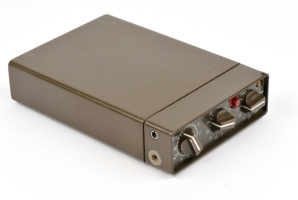
Like the other modules of the SP-20 radio set, the transmitter measures
115 xc 105 x 32 mm and has all controls and connections at the front panel.
A metal rail at the top surface allows the matching antenna tuner to be
mounted on top.
The transmitter is powered by a 12V DC source that should be connected to
two banana sockets at the front. Also at the front are two banana sockets
for the connection of a morse key or an early burst encoder, such as the
NATO RT-3.
The set was originally crystal operated and was suitable
for the 2...24 MHz frequency range.
|
|
|
In the late 1970s, the crystal was
replaced by the KS-30 frequency synthesizer.
The transmitter was designed for sending messages in
morse code
and operates in CW (A1), with an output power of
~ 15 Watts. When tuning the antenna however, an output power of 10 mW
is used.
The output of the transmitter is connected to the input of the
ASG-6800 antenna tuner.
When using the KS-30 frequency synthesizer, the transmitter has also be
used in FSK (F1) mode, in which case the burst encoder should be connected
to the peripheral socket of the KS-30 synthesizer.
|
-
Below 10 MHz, the transmitter produces an output power of 20W.
|
All controls and connections of the S-6800 are at the front panel,
as shown in the diagram below. The unit is powered by a 10...15V
DC power source (typically 12V from a car battery) that should be
applied to the banana sockets at the center of the front panel.
The unit is switch ON with the power switch to the left of the red
banana socket. The battery voltage can be checked by briefly pressing
the Battery Test button along the lower edge. The indicator should
be in the green area.
When operating the transmitter with a crystal, the crystal should be
inserted into the appropriate socket, which is shown here with a protective
plastic cap installed. When used in combination with the KS-30 synthesizer,
the latter should be connected to the peripheral socket at the left.
A long-wire antenna and a suitable counterpoise can be connected directly
to the banana sockets at the right, but these sockets should only be used
if no antenna tuner is available. In normal use, the ASG-6800 tuner should
be connected to the SMB socket at the right center. When tuning the antenna,
the Tune-switch should be pressed, which results in a 10mW output signal.
The controls on the ASG-6800 tuner should then be adjusted for a maximum
reading of the indicator.
|
The ASG-6800 antenna tuner was designed for use in combination with the
S-6800 transmitter. Like the transmitter, it was manufactured by AEG Telefunken
in the mid 1970s (1975-1977).
The tuner was connected to the transmitter by means of a short coaxial
cable with an SMB-connector at both ends.
At the bottom it has two rigs that allows it to be slotted onto the
S-6800 transmitter (see above).
➤ More information
|
|
|
|
|
Analogue synthesizer
STEU-6800
|
|
|
Along with the S-6800 transmitter, a complex analogue frequency synthesizer
was developed, that allowed the set to be operated on any of 1296 front panel
selectable channels.
The analogue synthesizer was too complex in operation however, as the channel
number did not have a direct relation with the corresponding frequency, and the
device was abandoned in favour of individual crystals.
➤ More information
|
|
|
|
|
Digital synthesizer
KS-30
|
|
|
Initially, the S-6800 transmitter was crystal operated. Later, an external
synthesizer unit (KS-30) was developed by Pfitzner. This was probably
early in 1983.
The sythesizer allows a frequency coverage of 2-24MHz in 1kHz steps.
It was added to all existing SP-20 stations and connected to the transmitter
via a multi-pin connector on the left. A rather long cable was supplied to
connect the KS-30 to the S-6800.
➤ More information
|
|
|
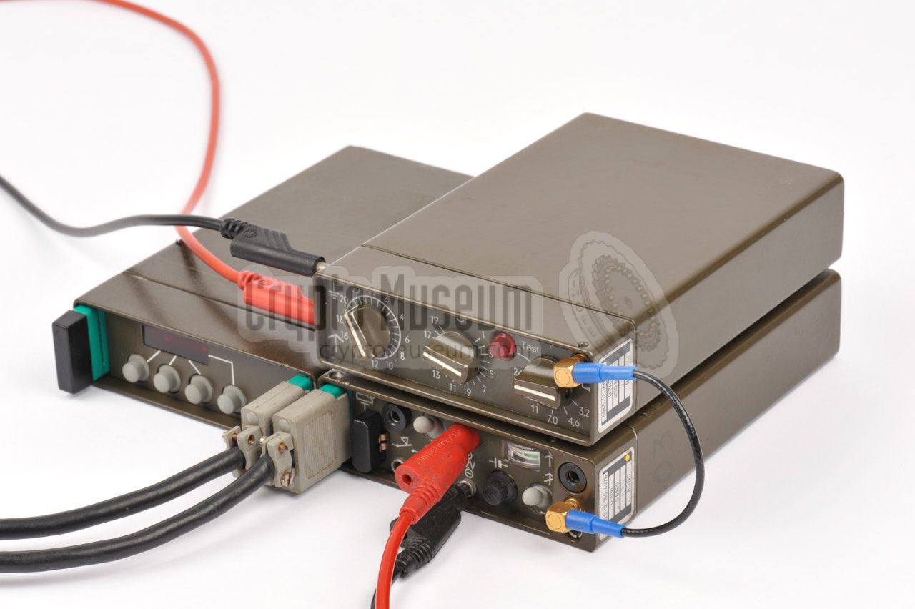
With the military variant of the SP-20, it was common practice
to connect the synthesizer to the transmitter by means of
a one meter cable.
With the stay-behind version of the set however,
it was more common to place the synthesizer to the left of the transmitter
and connect the two units by means of the small connection block shown
in the image on the right [1].
|
|
|
|
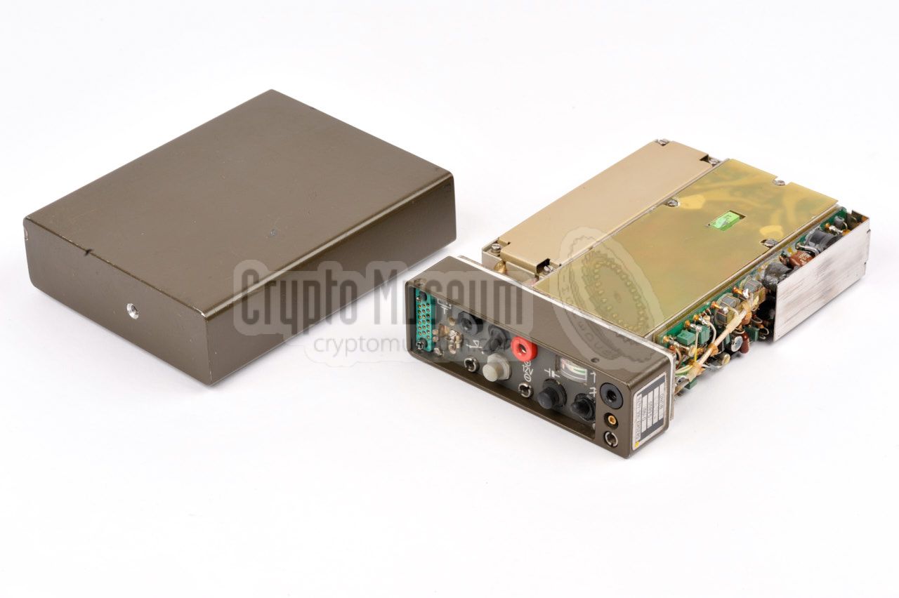
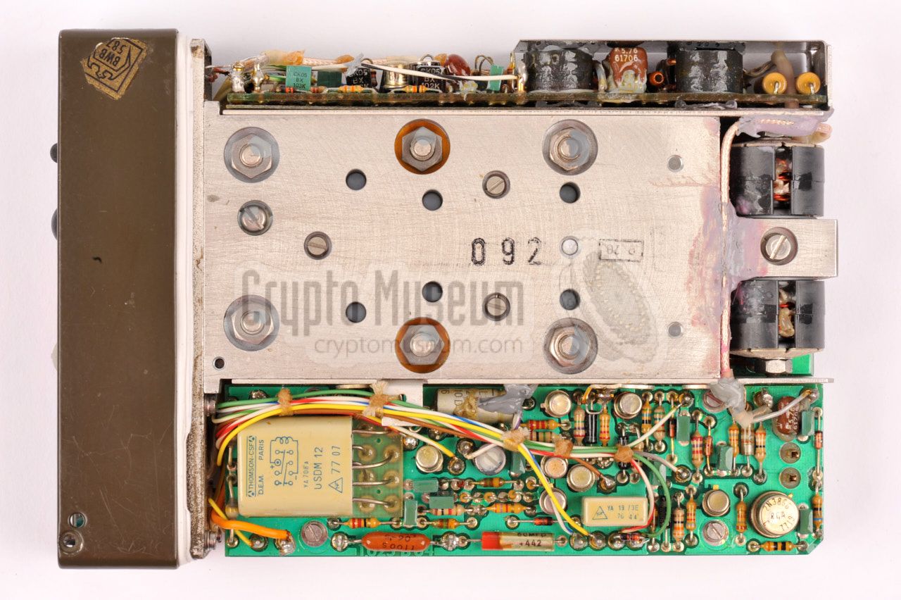
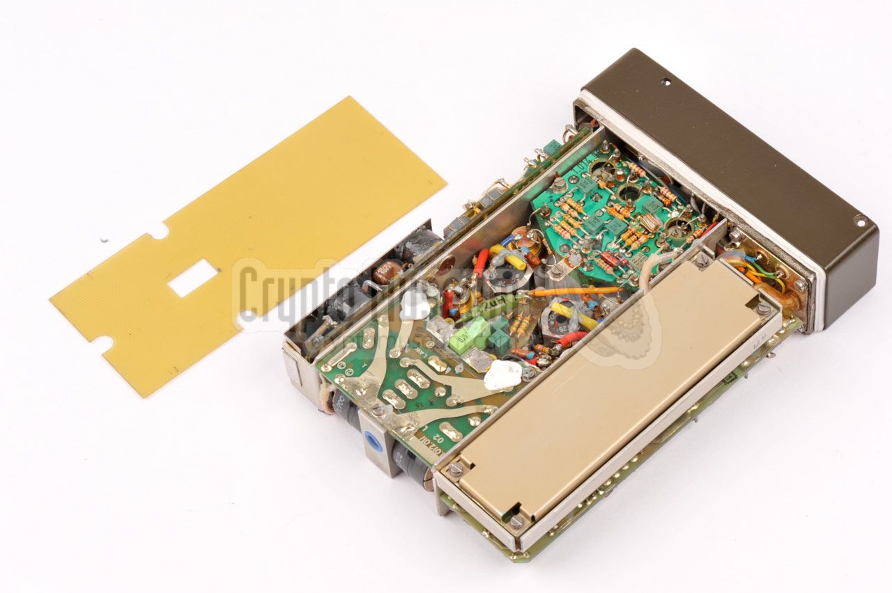
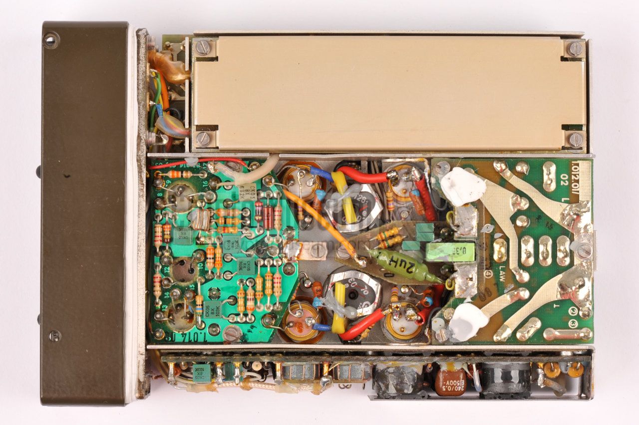
The highly compact S-6800 transmitter is beautifully built. The interior
can be accessed by removing a single screw from the rear end, and sliding
off the case shell. The entire construction is built on a metal frame
that is mounted to the front panel,
just like with the other modules.
|
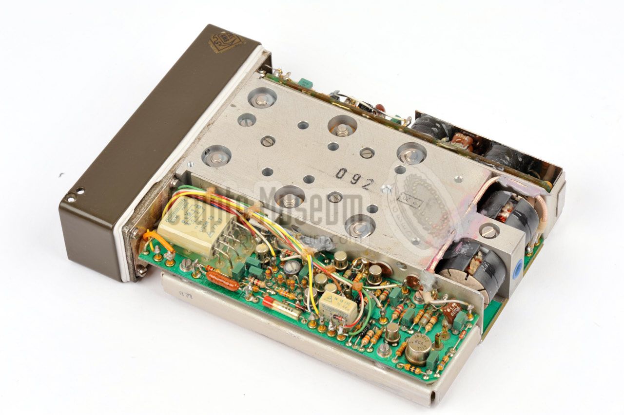
The image on the right shows the top side of the interior, with the large
heat sink taking up most of the space. A total of seven transistors are
mounted to this heatsink, two of which are used in the PA-stage.
The other transistors are used in the driver stages. At the front left
is a relay.
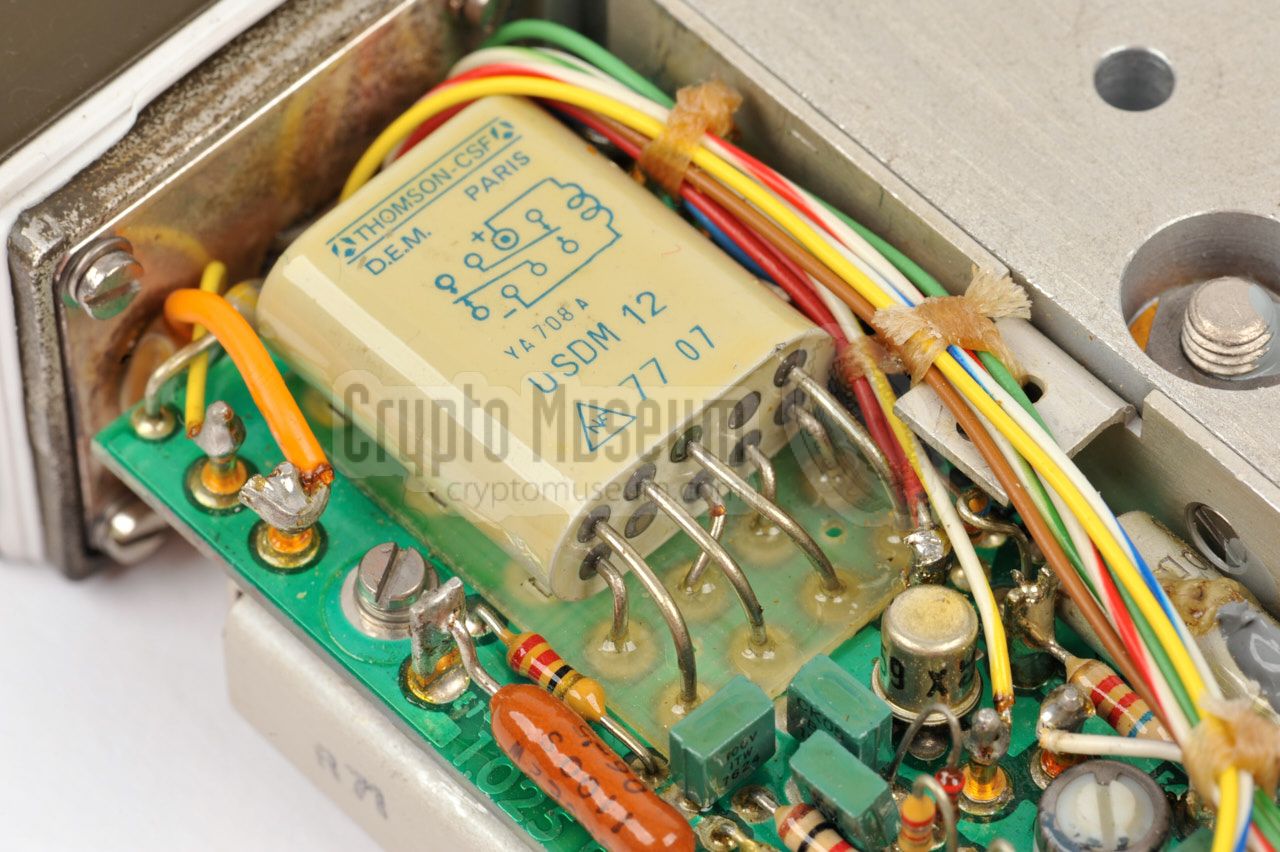
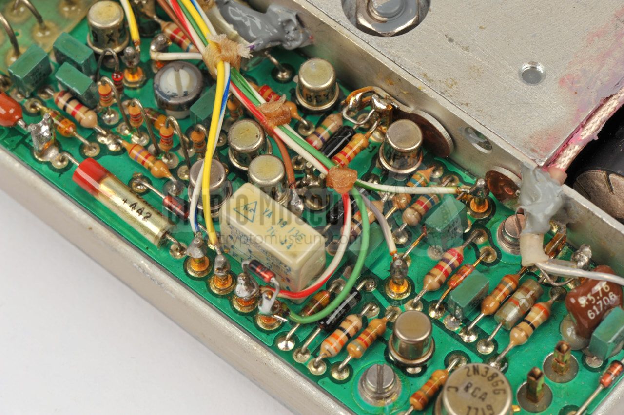
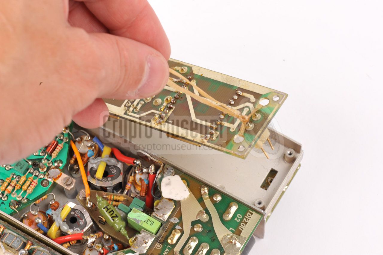
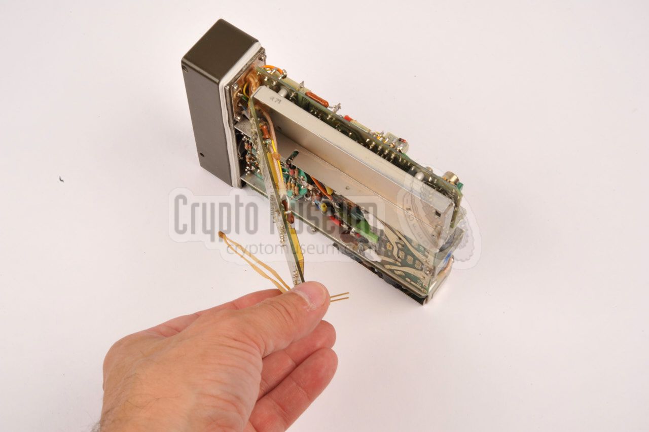
At the bottom side in the actual transmitter PCB, plus a narrow PCB that
is covered by a metal panel. This PCB contains two hybrid building blocks
marked KS 411 B, which is the oscillator, and KSB 408 B, which is the
oscillator amplifier. Information about these parts is available below.
|
|
|
The build quality of the transmitter is extremely high, and only first
class components are used from a wide variety of manufacturers. When looking
at the interior, one can't help but noticing the enormous experience of the
Telefunken engineers in creating robust and reliable equipment.
|
|
Development of the S-6800 transmitter at Telefunken started in 1966 and took
until approx. 1970. During that time, various designs were tried and much
time was spent on miniaturization, as the circuits had to fit inside the
cramped space of what would become the standard enclosure.
|
The image above shows an early prototype of the Kleinsender
(miniature transmitter) S-6800 that was developed in 1966 by Fritz
Arends, one of Telefunken's key developers. The functional specification
was drawn in June 1966 and the first
prototype was finished in November of that year.
It delivered an output power of 15W.
Immediately after the prototype was released, development of the
final design of the S-6800 was started. The requirements had meanwhile
been adjusted by the first customer. It had to produce an output power of
~15W and it had to fit inside the smaller (now familiar) rectangular enclosure.
The design of the upgraded S-6800 transmitter was finished in or around 1968.
|
|
|
By 1970, the transmitter was ready to be rolled-out and a year later, in 1971,
the official circuit diagrams were released [A].
Note that the circuit diagrams were
updated in 1976, after several small modifications had been processed.
The image above shows developer Fritz Arends in later years,
holding one of 'his' beloved SP-20 spy radio sets under his arm.
The image was taken at the Telefunken museum in Ulm (Germany).
Photograph via Jim Meyer [1].
|
-
Document kindly supplied by Jim Meyer [1].
|
|
|
|
Any links shown in red are currently unavailable.
If you like the information on this website, why not make a donation?
© Crypto Museum. Created: Monday 29 August 2016. Last changed: Monday, 14 September 2020 - 08:56 CET.
|
 |

|
|
|


![Connection block for fitting the KS-30 synthesizer directly to the S-6800 transmitter. Photograph by Jim Meyer [1].](img/connection_block_large.jpg)


![Fritz Arends, developer of the S-6800 transmitter, with an SP-20 under his arm. Photograph via Jim Meyer [1]. Reproduced here by kind permission.](img/fritz_arends_large.jpg)