|
|
|
|
|

|
|
Germany SBO SF SP-20 S-6800 → STEU-6800 →
Digital frequency synthesizer · 2-24 MHz
KS-30 was a digital PLL-based frequency synthesizer, developed in the
late 1970s by Heinrich Pfitzner GmbH
in Bergen-Enkheim (Germany),
for use with the German SP-20 spy radio set.
It was intended as a replacement for the crystals, and connects directly
to the 20-pin socket at the front panel of the
Telefunken S-6800 transmitter, acting as the driver stage
(German: Steuer-Sender).
|
The synthesizer allows any frequency between 2 MHz and 24 MHz
to be selected with increments of 1 kHz, and directly produces the
transmission frequency. The 20 mW output is fed directly to the
transmitter which amplifies it to approx. 30 Watts before
passing it on to the antenna tuner.
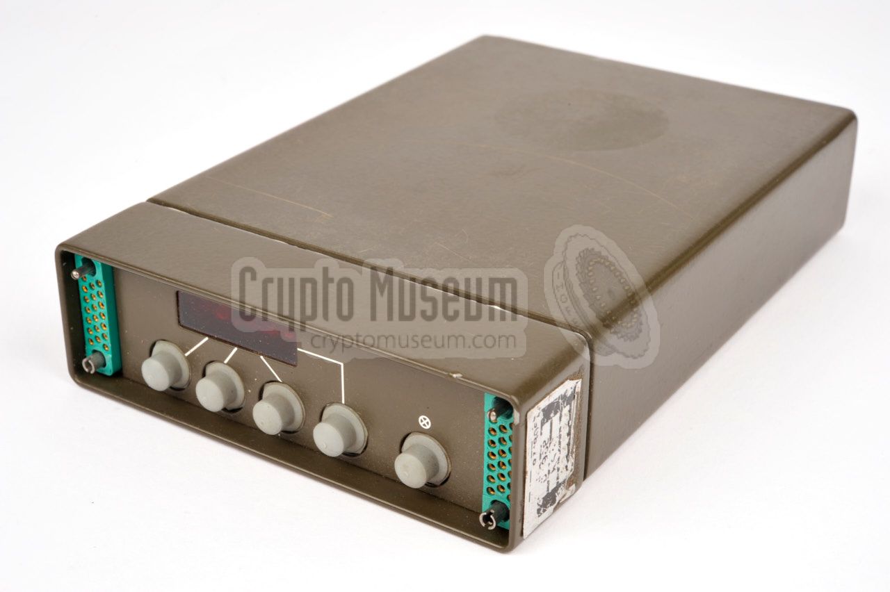
The image on the right shows a typical KS-30 synthesizer in a military
green enclosure. It was also available in a grey enclosure, in which case
it was intended for the Stay-Behind use of the radio
set. It had a metal rail at either side of the case, allowing the units to
be mounted sideways.
|
|
|
The KS-30 synthesizer was introduced several years after the
SP-20 spy radio set itself, which was initially
operated with quarz crystals. The KS-30 was connected to the
Telefunken S-6800 transmitter
by inter-connecting the 20-way sockets of the two devices.
The synthesizer is a critical part of the SP-20 radio set,
and many of the surviving examples appear to be exhibiting problems
after a shelf life of more than 30 years.
Most of these problems can be solved however.
|
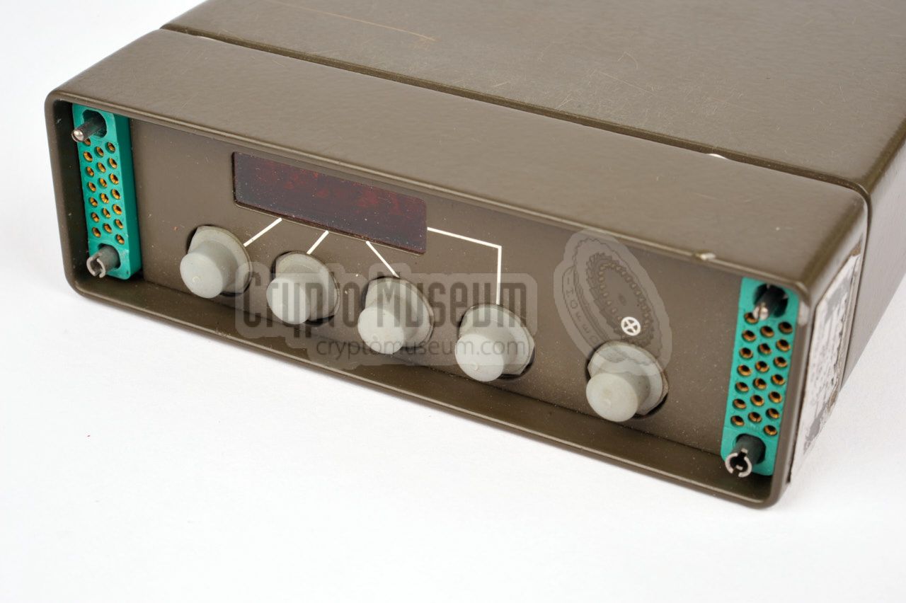
All controls and connections are located at the front panel.
At the top is a 5-digit 7-segment red LED display that shows the currently
selected frequency. A decimal dot separates MHz from kHz. Four push-buttons
are used to select the desired frequency by incrementing each unit.
To save energy, the display is turned off after a few seconds, leaving
the decimal dot ON to show that the device is running. The display can be
re-enabled by pressing the lamp button at the far right.
The image above shows the front panel of the KS-30 whilst power is
supplied to the unit and the display is in stand-by mode.
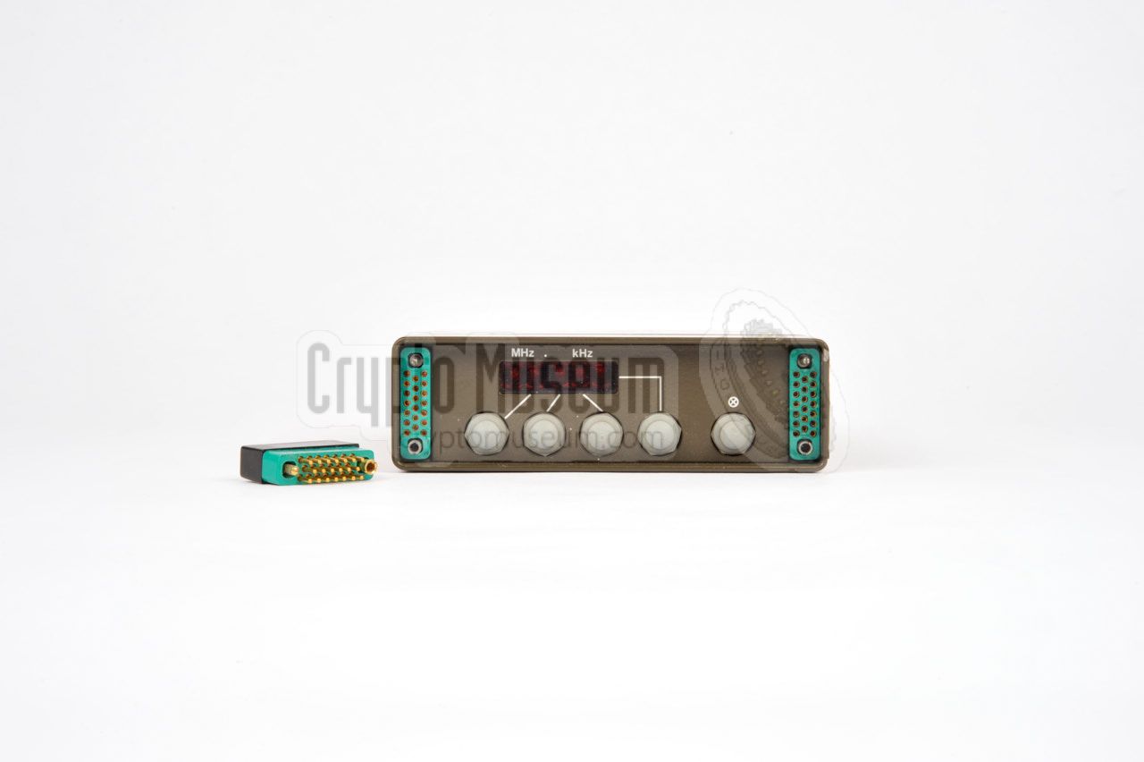
Note that the decimal dot of the display is lit. In the image below,
the display is re-enabled by pressing the lamp button at the right.
Frequency is set to 7.125 MHz.
Two 20-pin sockets are present at the front panel. The one on the left is
used for connection of peripherals, such as a high-speed morse burst encoder.
When no peripheral is connected, a terminator plug should be present in this
socket as shown in the image above. The socket at the right is used for
connection to the Telefunken S-6800 transmitter.
Shown here with the cable.
|
- Military version
The military variant can be recognised by its olive green enclosure.
It is connected to the S-6800 transmitter by means of a 1 metre shielded
cable with 20-pin SME20P plugs at either end.
The full wiring of this cable is given below.
- Stay-behind version
The stay-behind variant can be recognised by its grey enclosure.
It has a metal rail at either side of the body, allowing it to be mounted
sideways to the left side of the (grey) S-6800 transmitter. It is connected
to the transmitter by means of a small connection block.
|
|
The KS-30 has two modes of operation: A1 (CW) and F1 (FSK).
A1 modulation is used with the older generation of burst encoders, such as
the RT-3. Most military sets were used in this mode.
F1 should be selected when using the faster
Speicher
and the much faster MMP burst encoders.
|
Most stay-behind sets were used in F1 mode.
The desired mode of operation is selected by means of a jumper
inside the unit, on board 1.
For this, the case of the KS-30 has to be opened. Remove the single screw
at the rear of the case and slide off the case shell. Next, remove the
metal cover from the top of the frame by taking out a single screw.
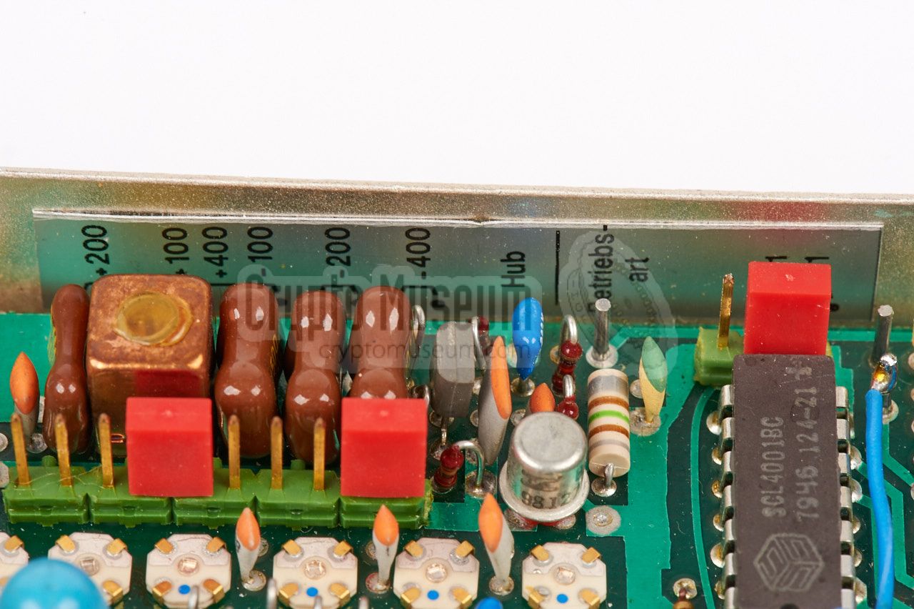
The jumper is on the largest board at the top side and is marked
Betriebsart (mode), as shown in the image on the right.
In the left position, A1 is selected,
whilst in the right position, F1 is selected, as in the image.
|
|
|
When using A1, the burst encoder
(typically an RT-3) should be connected
directly to the keying input of the transmitter, just as it was done
before the KS-30 synthesizer was introduced. In this mode, the
terminator plug
should be installed in the leftmost socket of the KS-30 synthesizer.
When using F1 mode, the fast burst encoder should be connected to the
leftmost socket of the synthesizer (instead of the terminator). The
encoder uses two hardware lines to control the radio station: the
line Auftastung, which enables the transmitter, and the line
Tastung, which is used for sending the data in high-speed
morse code.
Full connections are given below.
|
With the military variant of the SP-20, it was common practice
to connect the synthesizer to the transmitter by means of
a one meter cable.
With the stay-behind version of the set however,
it was more common to place the synthesizer to the left of the transmitter
and connect the two units by means of the small connection block shown
in the image on the right [1].
|
|
|
|
In order to minimise the risk of discovery by means of
Radio Direction Finding (RDF),
a burst encoder
was often used with the SP-20.
It allows a pre-recorded coded message to be played
back in morse code
at very high speed, in order to keep the transmission as short as
possible.
|
The first burst encoder that was issued with the SP-20 was this
electro-mechanical RT-3 unit.
A small military-grade metal box that allowed a message of no more than
25 characters to be stored mechanically. Once on-air, the message
was played back by operating a hand crank.
Later, more advanced burst encoders were issued, such as the
GRA-71,
MMP
and Speicher.
➤ More information
|
|
|
The Speicher (memory) was an electronic burst encoder
for sending numbers at high speed in
morse code. It was powered
directly from the mains and was housed in a similar case as the
units of the SP-20 spy radio set.
The Speicher was probably issued in the 1970s to replace the
rather limited RT-3.
Eventually it was replaced itself by the
more advanced MMP.
➤ More information
|
|
|
The MMP was a fully electronic high-speed (1200 baud) burst
encoder that was used with both the
SP-15 and the SP-20 spy sets.
The MMP replaced older devices, such as the mechanical
RT-3,
the American AN/GRA-71
and the early electronic Speicher.
It could hold more than 1000 letters and numbers in its battery-bakced
CMOS memory and could send them at various speeds between 15 and 1200 baud.
➤ More information
|
|
|
The block diagram below shows how the KS-30 works.
At the bottom right is the digital section with the ÷n (divide-by-n)
counter at its heart. The divider drives the display logic and is
also in the feedback loop of the Phase-Locked Loop (PLL) circuit
that produces a 77-99 MHz signal at its output. This signal is
mixed with a modulated 75 MHz signal, that in turn is derived from
a TCXO generated 74.97 MHz reference signal, mixed with an FSK modulated
signal from a 3 MHz VCO.
At the bottom left is the internal power supply unit (PSU) that
converts the incoming 10...15V DC voltage into a stabilized 9.8V
for the analogue circuitry and 9.5V for the display logic.
An extra stabilized 7.5V rail is provided for the 3 MHz VCO
and its buffer amplifier. The keying logic, at the top of the
block diagram, can be configured
for FSK (F1), in which case jumpers are used to select the desired
frequency shift, or CW (A1), in which case the VCO modulator is
bypassed.
|
|
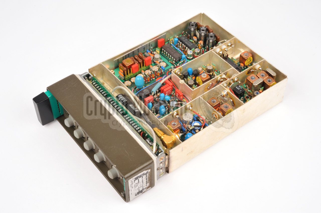
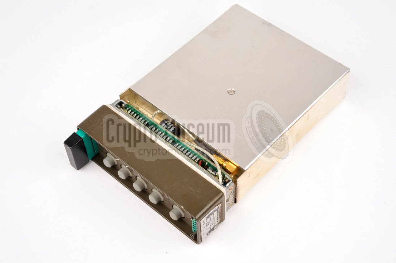
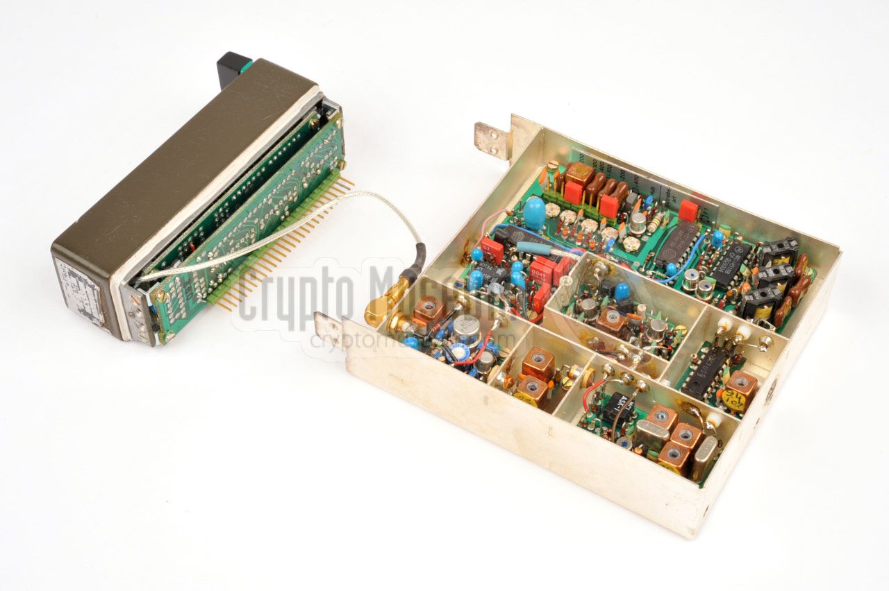
Getting access to the interior of the KS-30 is extremely simple.
Just remove the only screw from the rear side of the case and slide away
the case shell. This reveals a metal frame that is mounted to the front
panel. All electronics are housed inside this frame and
behind the front panel.
|
Some of the digital ICs are located behind the front panel. They
are used for scanning the keyboard and driving the LED display.
The actual synthesizer and the analogue electronics are located
inside the frame. After removing the lid from the frame, six
compartments become visible, as shown in the image on the right.
A total of 6 printed circuit boards (PCBs) are located inside
the silver-plated compartments of the frame, whilst the largest
one (board number 3) is located at the bottom. In addition,
three stacked PCBs are mounted to the front panel.
|
|
|
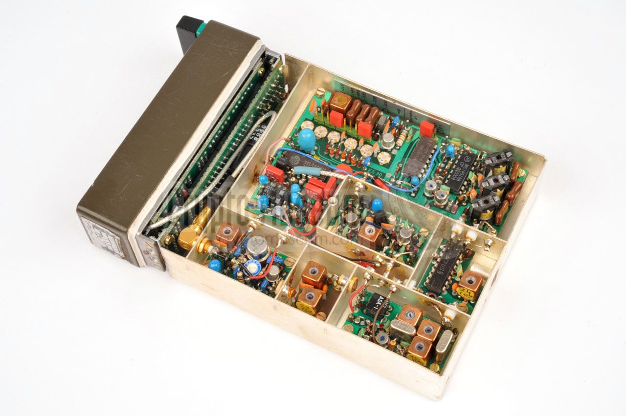
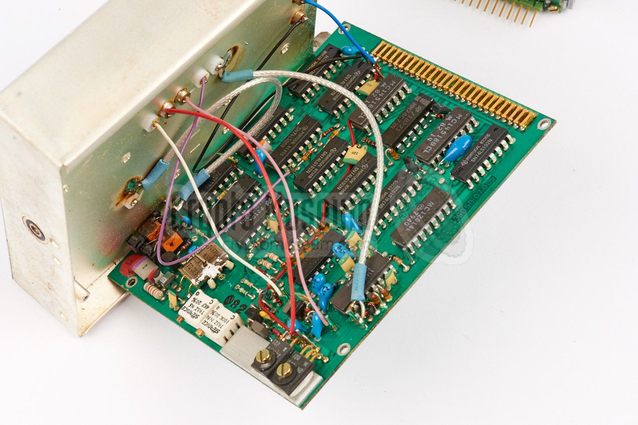
The image above shows the interior of the KS-30 synthesizer after
removing the lid of the compartmented frame. It is
attached to the front panel by means of two screws at either
size and can easily be removed.
The front panel is connected to the digital board at the
bottom by means of a 27-pin header, whilst a separate teflon
coax wire is used for the 20mW RF output.
|
|
The boards are numbered as follows:
|
- PLL, keying logic
- VCO
- PSU, TCXO, prescaler, counter, memory
- Multiplexer
- Display
- Mixer
- Filter and amplifier
- 24 MHz filter
- Output amplifier
- Keyboard
|
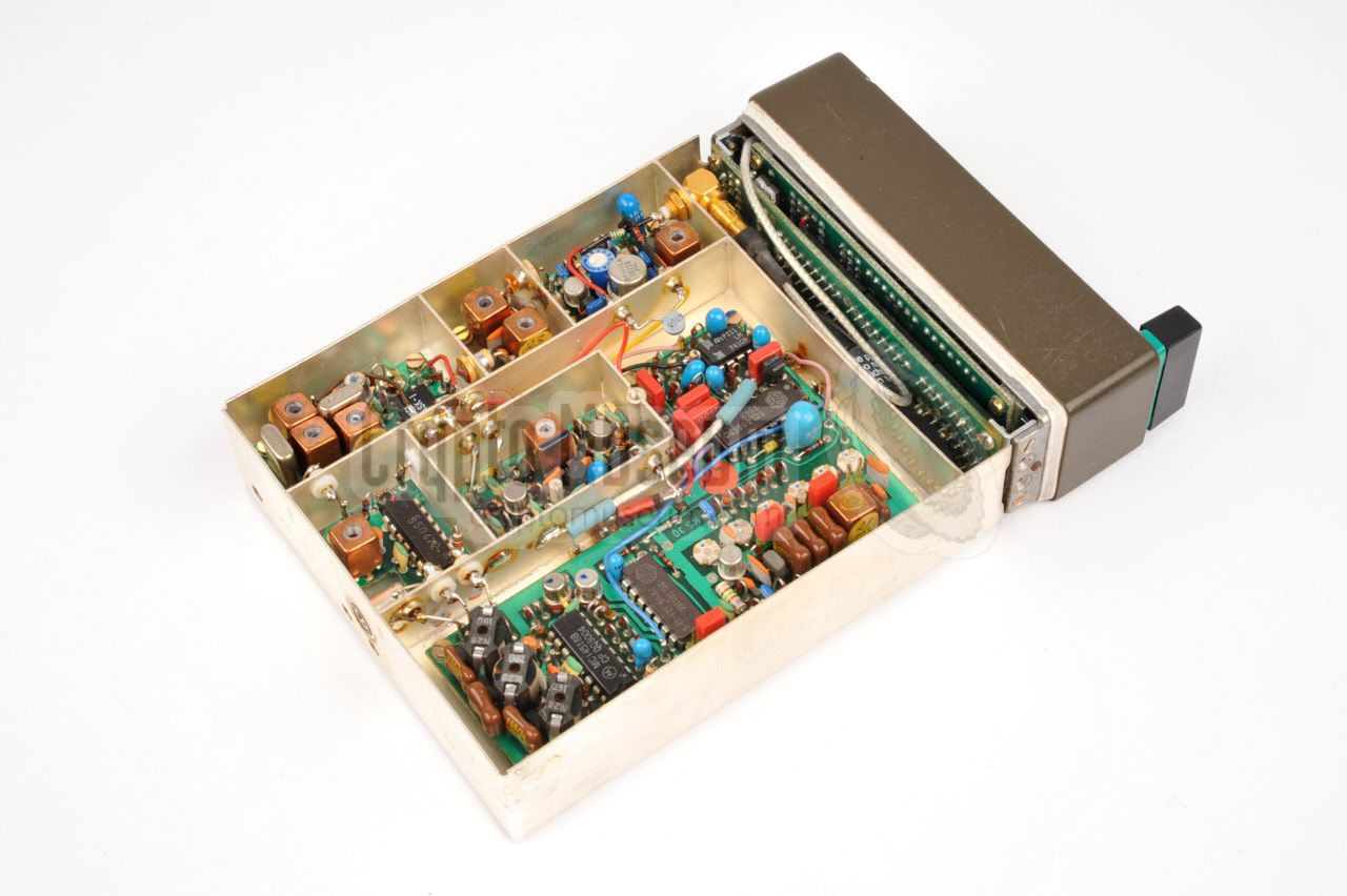
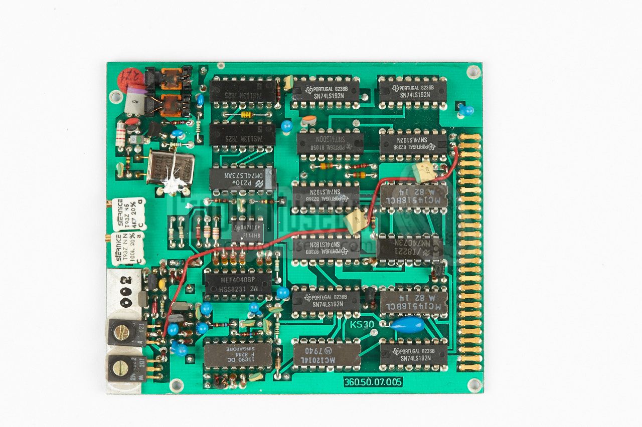
Note that boards 4, 5 and 10 are fitted behind the front panel as
a sandwich of three boards, and that the largest board (board number
3) it at the bottom side, in the position as shown above.
This board holds all digital parts, the power supply and the
reference oscillator. It is connected to the analogue parts via
a series of feed through capacitors in the frame. The front
panel connects to board 3 via a large 27-pin connector.
The image below shows the position of board 3:
|
|
The synthesizer is one of the most critical parts of the SP-20
radio station. It contains a mixture of analog and digital
parts and is difficult to align. Due to aging of the components
it is very likely that a surplus KS-30 no longer works (correctly)
after a storage period of more than 30 years.
|
- Solder case of reference crystal to ground
The 74.97 MHz refrence crystal on board 3, appears to be picking up a lot
of noise from the surrounding circuits, resulting in a high level of
phase noise in the output signal. Although the crystal is held in
place by a wire bridge that is soldered to ground, this bridge does not
make proper contact with the casing of the crystal. It is advised to
solder the head of the crystal case
directly to the ground plane of the PCB.
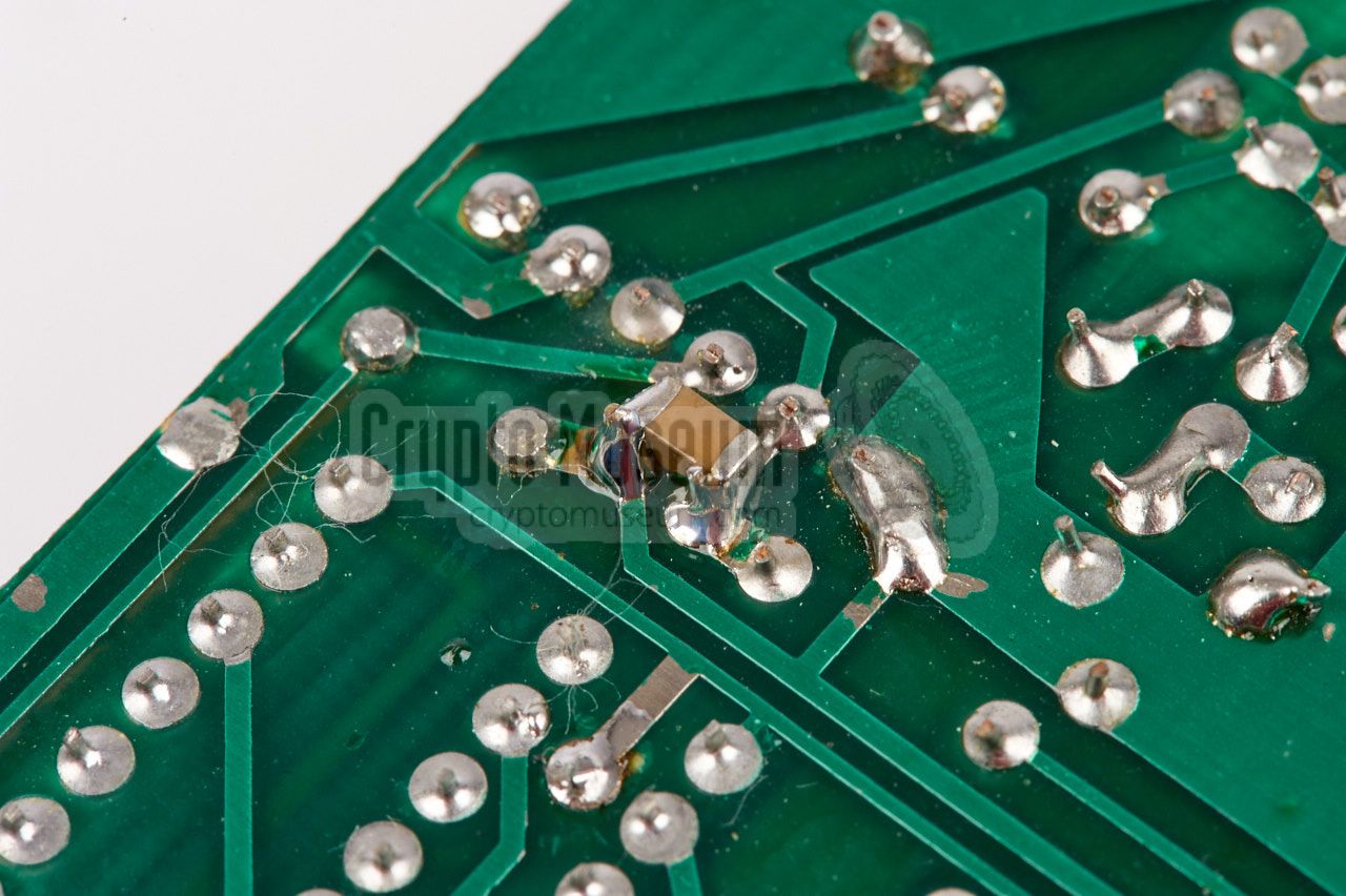
- Replace 10nF capacitor by 10nF + 10µF
The quality and value of capacitor C19 on board 3, is insufficient to
effectively eliminate phase noise caused by power rail noise. It is advised
to replace C19 by a high-quality 10nF capacitor. When doing this, it is
best to add a 10µF (ceramic) capacitor in parallel. Use an SMD variant
for this,
so that it can easily be added at the solder side of the board.
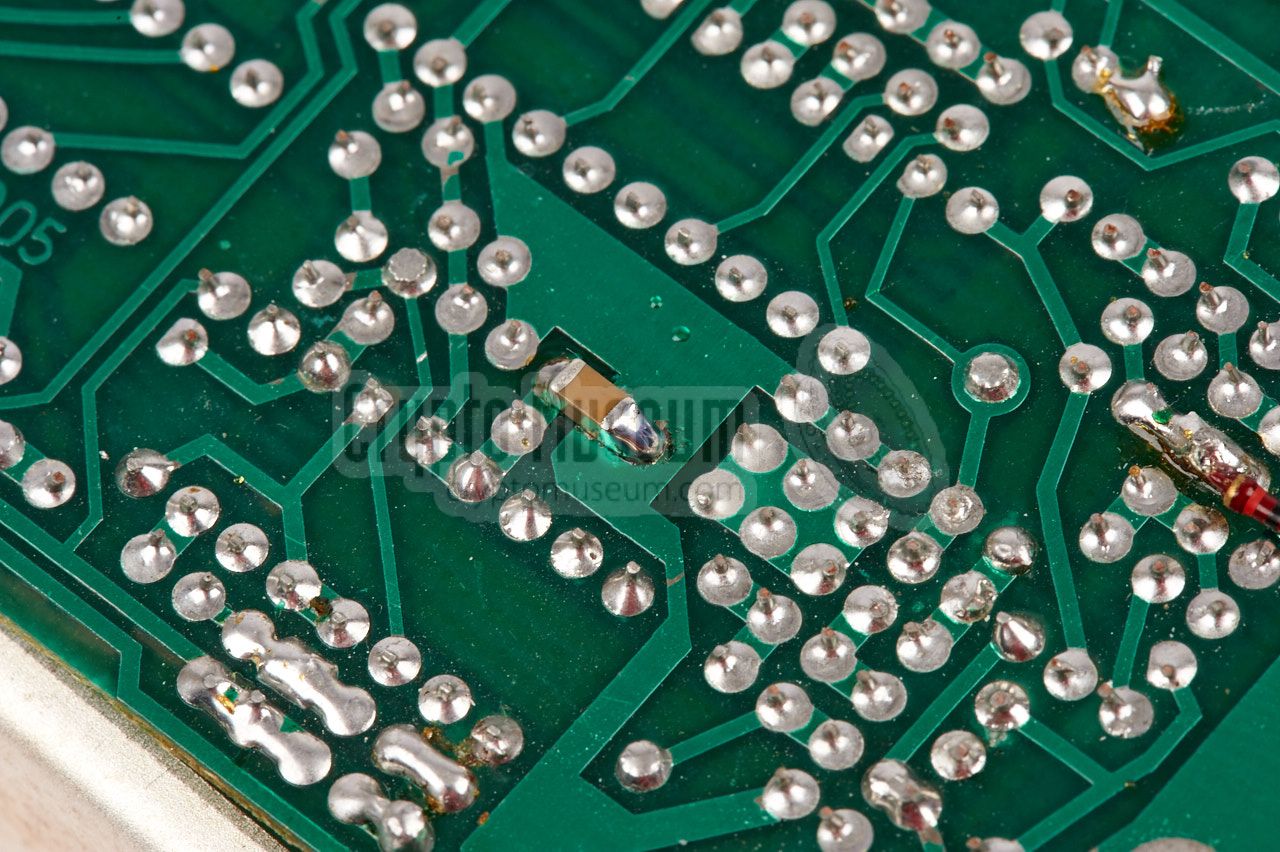
- Add 10µF
In order to further reduce noise on the power rail, add a 10µF ceramic
capacitor to board 3, between the top of R19 (the supply rail) and ground.
This reduces the feedback from the +18V generator that is built
around V05 and V06.
- Check 5V1 Zener Diode (D20)
The 10V rail is divided into two 5V rails by using a 5V1 zener diode to
drop down by 5V. This is done to allow the 11C90 pre-scaler to be powered
by -5V. To prevent unnecessary dissipation, half the digital ICs are
connected to the upper 5V rail, whilst the other half is connected to
the lower 5V rail. This is possible as most signals are AC-coupled.
Due to the high rush-in current of the 11C90, the voltage on the lower 5V
rail is briefly driven at a much higher voltage, which potentially causes
some of the ICs to latch-up. Once an IC is in latched-up state,
it will draw too much current, causing damage to the 5V1 zener D20.
Check the condition of the diode and replace it if necessary.
- Add safety 6V2 Zener Diode
To avoid the above problem, it is wise to add a
6V2 zener diode between the 5V line and ground.
This prevents the voltage to the digital ICs from
going above 6.2V when turning the device on, and avoids a possible
latch-up in any of the digital ICs.
|
|
The table below shows the pinout of the leftmost socket as seen from the
front of the synthesizer. This socket is used for connection of peripherals,
such as a morse key or a high speed morse burst transmitter, like the
the Speicher
or the MMP. If the socket is unused,
a terminator
should be installed.
|
- n.c.
- Loop 1 1
- Loop 1 1
- n.c.
- GND
- Loop1 1
- GND
- Loop 2 1
- Loop 2 1
- 10...15V
- n.c.
- Loop 2 1
- 10...15V
- Tastung 3
- n.c.
- n.c.
- Auftastung 2
- Tastung 3
- n.c.
- Auftastung 2
|
|
|
The table below shows the pinout of the rightmost socket as seen from the front
of the synthesizer. This socket is used for connection to the transmitter.
The loop wires shown in the drawing reflect the internal
wiring of the socket, as given in the original circuit diagram [B].
|
- HF
- Loop 1 1
- Loop 1 1
- HF
- GND
- Loop 1 1
- GND
- Loop 2 1
- Loop 2 1
- 10...15V
- n.c.
- Loop 2 1
- 10...15V
- n.c.
- GND
- n.c.
- Auftastung 2
- n.c.
- n.c.
- Auftastung 2
|
|
-
These lines are 'cold' links between the left and right sockets.
They run straight from the peripheral to the transmitter and
are not connected to anything inside the synthesizer.
-
In A1 mode, Auftastung is used for the connection of a morse
key or a medium-speed burst encoder. The line Tastung should
be grounded, by means of a terminator plug.
-
In F1 mode, Auftastung is used to enable the transmitter, whilst
Tastung is used for keying the data with a high-speed burst
encoder. The line Tastung is only available on the leftmost socket.
|
|
|
Connecting to the transmitter
|
|
|
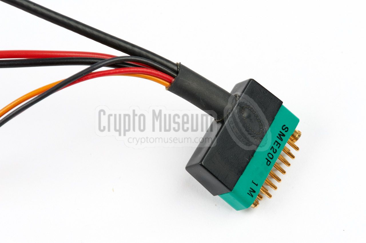
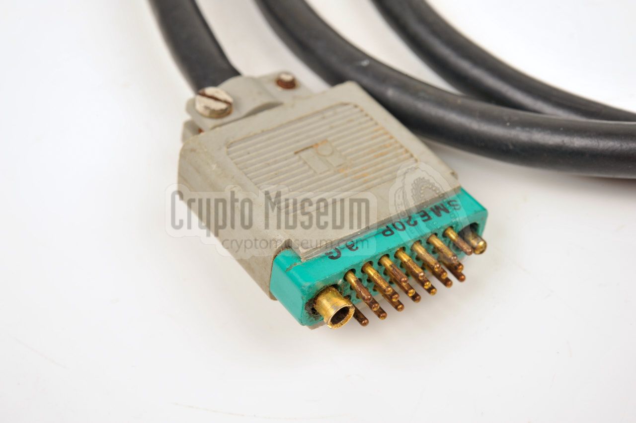
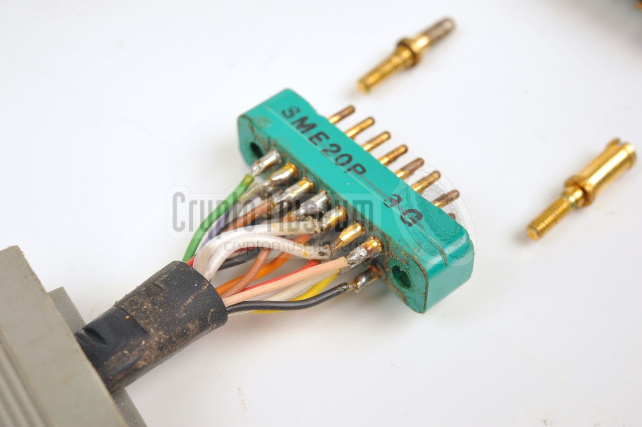
For connection between synthesizer and transmitter, a 16-way shielded
cable is used, with a 20-pin SME20P connector 1 at either end.
Two pins of this connector are used for connection of the shield and
two other pins remain unconnected. The wiring 2 of this connector, when
looking into the female sockets on the devices, is given below.
Both plugs are wired identically (1:1).
A suitable cable with a length of 1 metre was supplied with the military
version of the SP-20. This cable is also known as NSN 5995-12-188-3633.
A small connector block was generally used with the
(grey) Stay-Behind version of the radio set. The latter requires the
synthesizer to be placed adjacent (to the left of) the transmitter,
so that the connector block can be fitted to both sockets.
|
-
This is a military connector made by Winchester Electronics [3].
-
This is the same as the solder side of the male plugs.
|
|
|
Connecting the RT-3 burst encoder
|
|
|
|
When using the RT-3 burst encoder, it should be connected directly to
the morse key sockets at the front panel of the transmitter (not to the
synthesizer). In this case, the KS-30 synthesizer should be
configured for A1 mode,
and the terminator plug should be installed in the leftmost
socket of the synthesizer.
|
|
|
Connecting the Speicher burst encoder
|
|
|
|
When using a very high speed burst transmitter, such as the
Speicher
or the MMP, the KS-30 should be
configured for F1 mode. The keyer should be connected to the
leftmost socket on the synthesizer, rather than directly to the transmitter.
The diagram below shows the wiring of the cable between Speicher
and the KS-30 synthesizer, when looking into the sockets of the devices.
|
|
|
Connecting the MMP burst encoder
|
|
|
|
Connection to the later
MMP burst encoder is similar to Speicher,
but the cable has a LEMO plug at the MMP-end. The diagram below shows
the wiring of the cable that is used between the MMP and the KS-30,
when looking into the sockets on the devices. The line Auftastung
is driven by the MMP just before sending the message. It enables the
transmitter. Once the transmitter is stable, the actual message is sent
via the Tastung line in FSK. Note that the KS-30 should be
set to F1.
|
Note that the leftmost 20-pin socket on the synthesizer is not used,
but that a terminator plug
should be present in this socket for correct
operation of the set. Suitable terminator plugs were supplied with each
SP-20 radio set. The pinout of the terminator is given above, when
looking into the leftmost female socket on the synthesizer.
Pins E, H, R and V are connected together.
|
|
|
|
Any links shown in red are currently unavailable.
If you like the information on this website, why not make a donation?
© Crypto Museum. Created: Monday 29 August 2016. Last changed: Sunday, 12 February 2023 - 12:14 CET.
|
 |

|
|
|


![Connection block for fitting the KS-30 synthesizer directly to the S-6800 transmitter. Photograph by Jim Meyer [1].](img/connection_block_large.jpg)