|
|
|
|
|

|
|
← SP-20 ← Germany SBO SF S-6800 →
It is connected to the transmitter by means of a short coaxial cable
with SMB plugs at either end, and converts the 50 ohms unbalanced line
of the transmitter into a balanced one, suitable for connection of a
long-wire antenna and suitable counterpoise (ground) to the sockets
at the left.
Note that the ASG-6800 is a passive device, which means that it doesn
not have to be connected to a power source. It matches the output of the
transmitter to the connected (wire) antenna and ensures that as much energy
as possible is actually passed to the antenna.
|
|
|
Furthermore, it protects the transmitter - and in particular its power
amplifier (PA) - against damage caused by impedance mismatches.
Note that the antenna tuner is suitable for the entire 2...24 MHz
frequency range,
but that the best results are obtained when the length of the
antenna wires have a relation with the selected wavelength (λ),
for example ½λ or ¼λ.
|
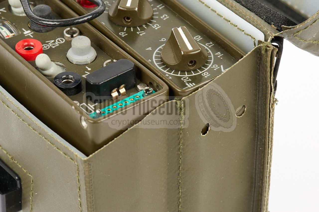
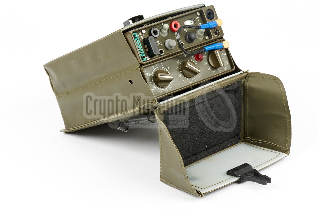
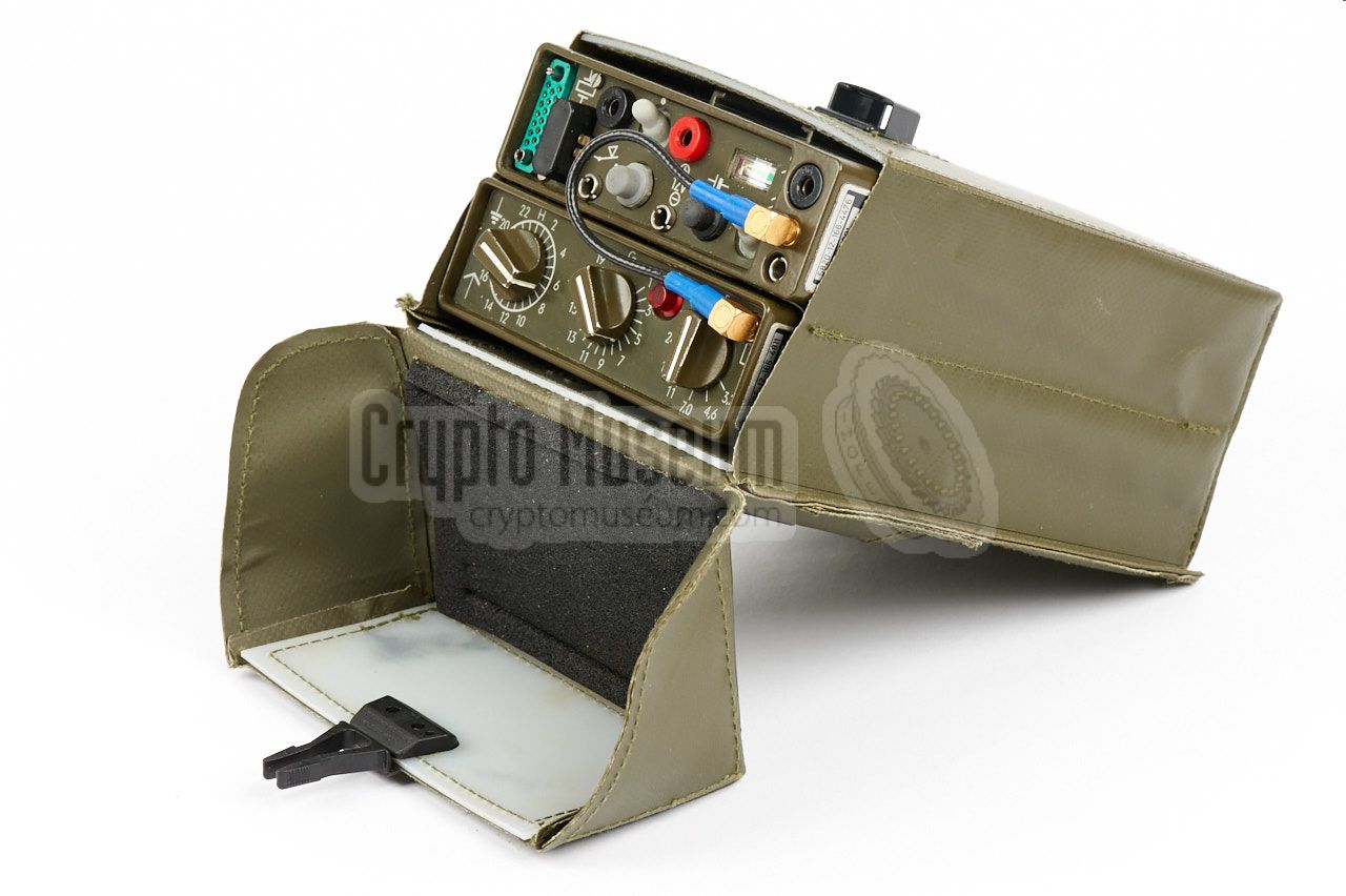
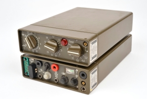
The antenna tuner is usually mounted on top
of the S-6800 transmitter,
using the metal rails on both devices. When carrying the two units in
the pockets of the webbing kit however, they should
be fitted the other way around, so that the two banana sockets for
connection of the antenna wires, can be reached through
two perforations.
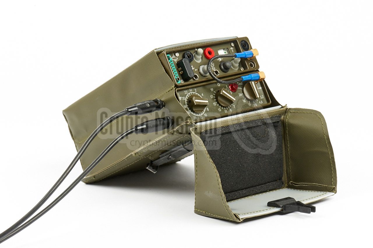
The image on the right shows the two devices installed in one of the
pockets of the webbing kit, with antenna and counterpoise wires connected
to the side of the antenna tuner.
|
|
|
All controls of the ASG-6800 are at the unit's front panel. There are
three rotary controls that should be adjusted for a maximum reading of
the indicator on the transmitter. A red indicator between the second and
the third knob can be used for checking the output of the transmitter.
The output of the transmitter is connected to the SMB socket at the top
right of the front panel. A long wire antenna should be connected to the lower
banana socket at the left side of the front panel,
whilst a suitable counterpoise should be connected to the upper socket.
To test the unit, proceed as follows:
set the rightmost dial to 'Test' and briefly press the morse key on the
transmitter. If full power (30W) is available, the red lamp
on the antenna tuner should be lit.
|
The ASG-6800 was designed especially for use in
combination with the S-6800 transmitter, which was also developed
by AEG Telefunken.
The two units are normally stacked together,
as shown in the image on the right.
For this reason, the ASG-6800 has a metal rail at the bottom surface
of the case, which mates with the metal rail on top of the S-6800.
The only connection between the two units is the short coaxial cable at
the right.
➤ More information
|
|
|
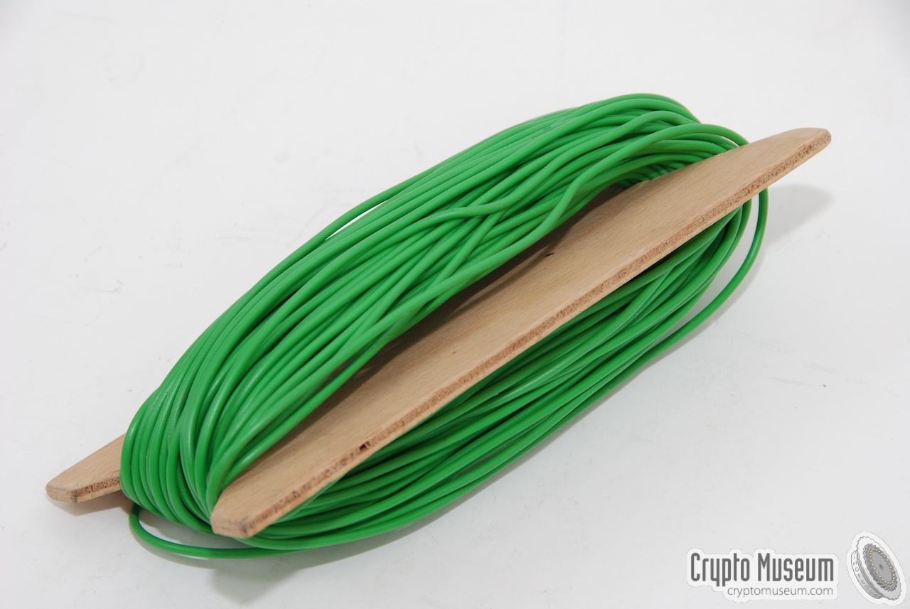
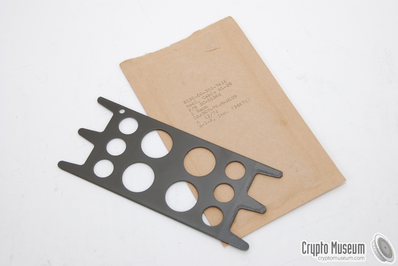
The antenna tuner makes it possible to use virtually any type of antenna
with the S-8600 transmitter. In practice, a long antenna wire was used on most
occasions. The antenna, and a suitable ground, are connected to the left
side of the tuner, via 2 banana-type sockets.
The images below show some of the typical wire antennas that were supplied
with the SP-20. Please note that transmitter and receiver each needed a separate
antenna.
|
|
|
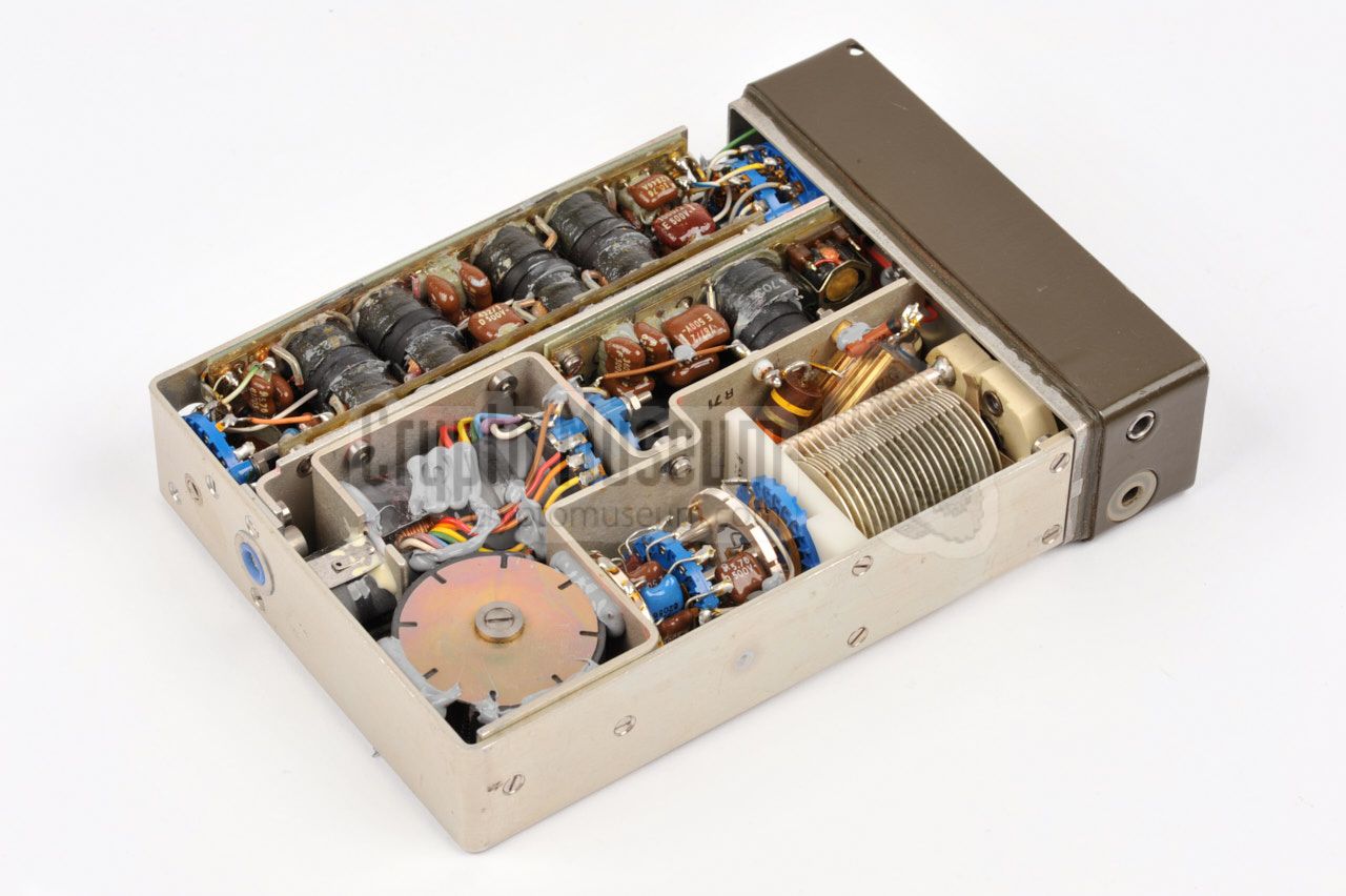
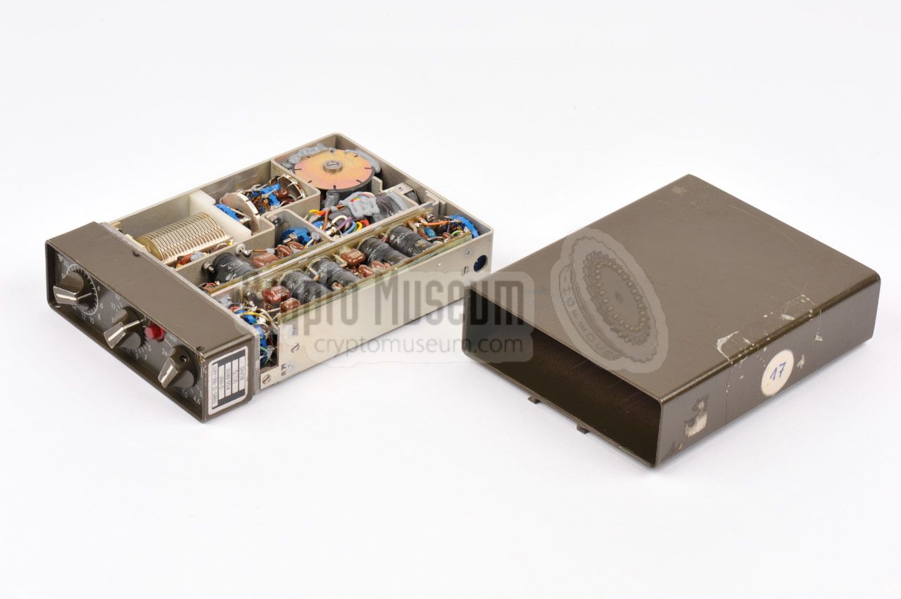
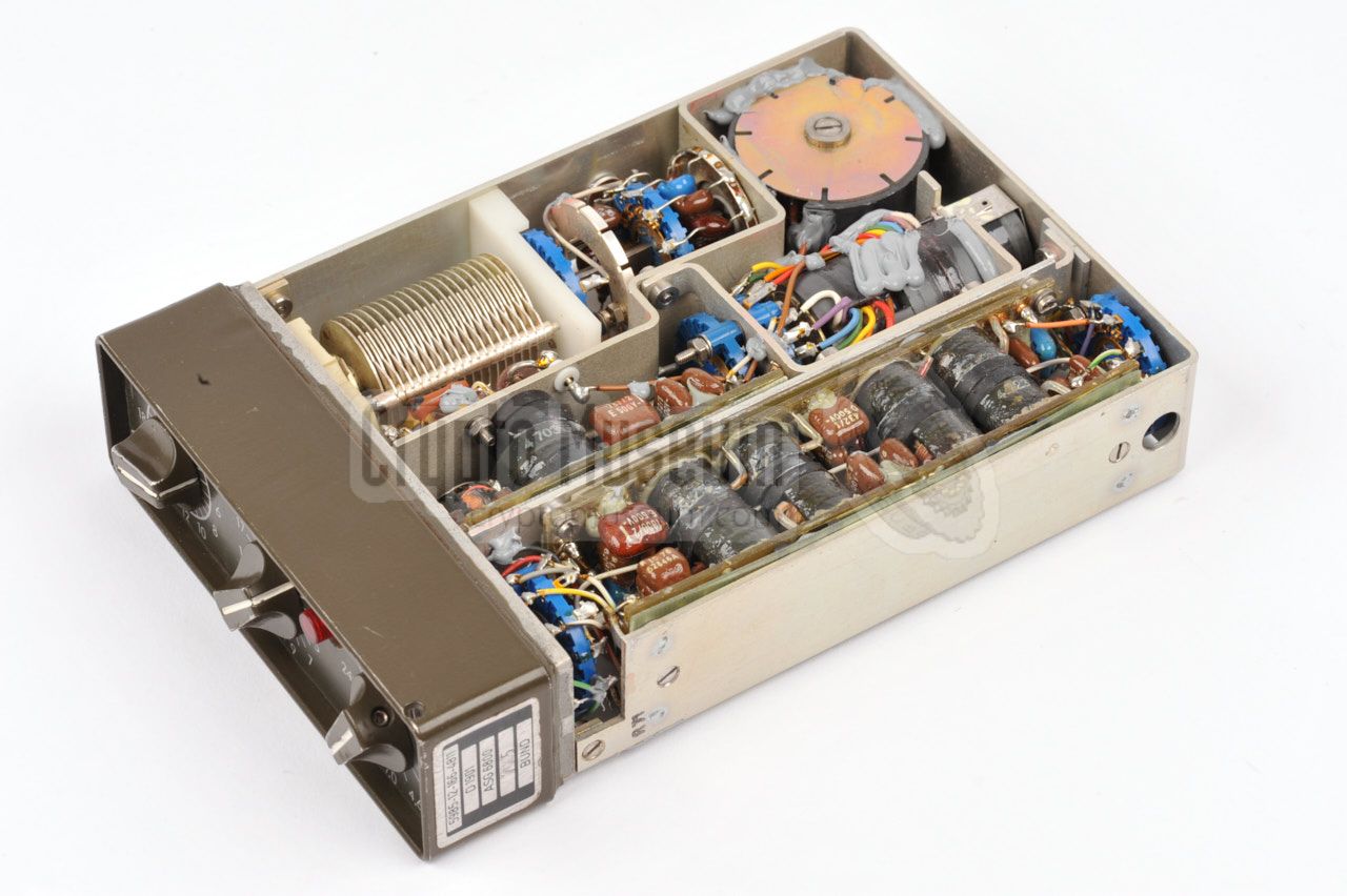
The interior of the ASG-6800 antenna tuner is easily accessible by removing
a single screw from the rear end, and sliding off the case shell.
All parts are held in place by a frame that is mounted to the front panel,
as shown in the image on the right.
Note the dummy load resistor that
is mounted to the frame, adjacent to the large tuning capacitor.
The full circuit diagram
is avaiable for download below [A].
|
|
|
-
Document kindly supplied by Jim Meyer [1].
|
|
|
|
Any links shown in red are currently unavailable.
If you like the information on this website, why not make a donation?
© Crypto Museum. Created: Monday 29 August 2016. Last changed: Monday, 14 September 2020 - 08:55 CET.
|
 |

|
|
|