|
|
|
|
|

|
Valve-based spy transmitter
The FS-7 was a minature valve based transmitter that was developed by
Pfitzner in Germany in the early 1960s. It was designed for the
SP-15 spy radio set and had the same size
as the FE-8 receiver. It was intended for espionage activities
and Stay-Behind Organisations (SBO)
and was suitable for
the transmission of morse code
signals on the HF radio bands.
The transmitter is the successor to the KSG-Sender
and is also known as BN-22
and (when modified) as the FSS-7.
|
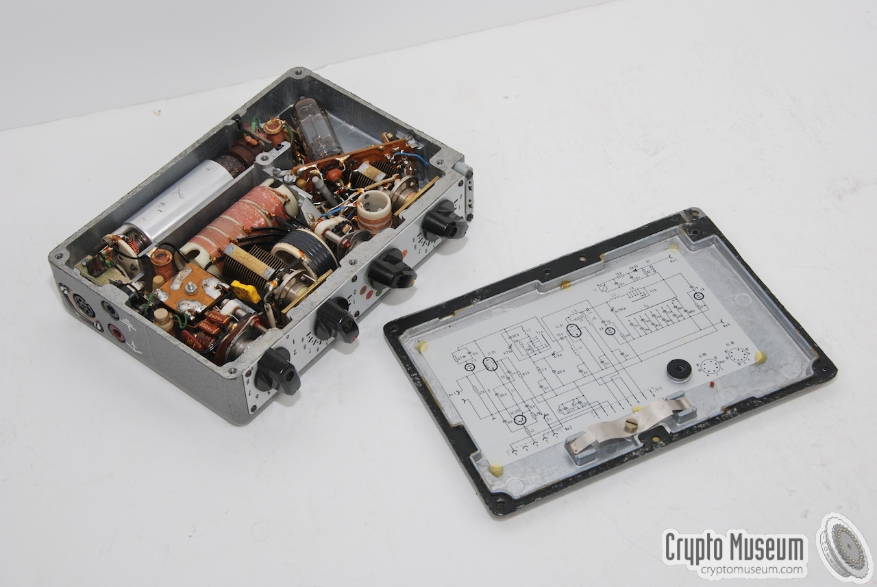
The transmitter was built around two valves (EL95 and EL81)
and produced a power output of 10W or 20W, selectable from the
power supply unit (PSU). A transistor (BC458) was used for the
manual morse keyer and the burst encoder.
The FS-7 was crystal operated and was suitable for all frequencies
between 2.5 and 24 MHz, divided over 6 colour-coded ranges. The
crystal was inserted into a socket at the far left of the front
panel. In The Netherlands, some FS-7 units were modified for
use in combination with an external
frequency synthesizer (see below).
|
|
|
The transmitter is only suitable for morse code (CW) and can be keyed
in two different ways [1]: either by switching the cathode of the oscillator
valve (EL95) or by keying the grid of the PA valve (EL81). The former
allows transmission speeds up to 100 baud and is typically meant for
manual keying. The second method allowed speeds up to 800 baud
and was typically used with external burst encoders, such as the
GRA-71
and the RT-3, and also with the
later Speicher burst encoder.
It is likely that
Frequency Shift Keying (FSK)
was later added to
the FS-7 by means of an external modification, in order to support
the faster and more versatile MMP burst encoder
in the early 1980s.
As the transmitter does not produce an audio tone when sending morse,
the telegraph key can be connected to the transmitter and the receiver simultaneously (sidetone).
The FS-7 was introduced by the German Intelligence Agency,
the Bundesnachrichtendienst (BND), in the early 1960s as the successor
to the 1957 KSG-Sender. In the early years, the burst encoder of the
KSG-Sender, the so-called Kurzsignalgeber (KSG) was used with the FS-7.
In the late 1970s and early 1980s, the FS-7 was replaced by the
fully transistorised SP-20 spy radio set.
|
|
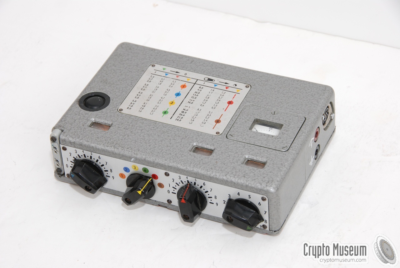
The transmitter covers 2.5-24MHz in 6 colour-coded ranges.
The 4 knobs at the front of the unit each have a differently coloured arrow
and a table on top of the unit is used to determine the settings for each
frequency range:
|
- 2.5 - 3 MHz (orange)
- 3 - 4 MHz (blue)
- 4 - 5 MHz (yellow)
- 5 - 8 MHz (green)
- 8 - 14 MHz (red)
- 14 - 24 MHz (brown)
|
A morse key (or keying device) can be connected to the transmitter in two
different ways. The standard method is shown in the drawing below.
It is suitable for speeds up to 100 baud. In this mode a transistor
(OC450 or BC458) is used for switching the cathode of the oscillator (EL95),
whilst the PA (EL81) is kept running. Note that pins 1 and 2 of the
5-pin DIN plug are shorted.
When using the RT-3, or indeed any other
type of burst encoder,
a different connection should be made inside the
5-pin DIN plug. As a result, the oscillator is kept running, whilst the
screen-grid voltage of the PA (EL81) is switched by the RT-3. This allows
speeds up to approx. 800 baud.
As the FS-7 does not provide an acoustical feedback when sending
morse code, a
special cable with a T-adapter
was supplied. It allowed the morse key to be connected
simultaneously to the FS-7 transmitter and to the side-tone
input of the FE-8 receiver
(i.e. in parallel with the morse key or the burst transmitter).
A third method for keying the morse code even faster, e.g. at 1200 baud,
was developed later, when the MMP burst encoder
appeared. As both methods
described above are not suitable for sending morse code at such high speeds,
a small FSK modulator
was added. It was inserted between the crystal socket
of the FS-7 and the crystal and connected to the key output of the MMP.
By switching an adjustable capacitor in parallel to the crystal, the
transmission frequency was changed in the rythm of the morse signal.
|
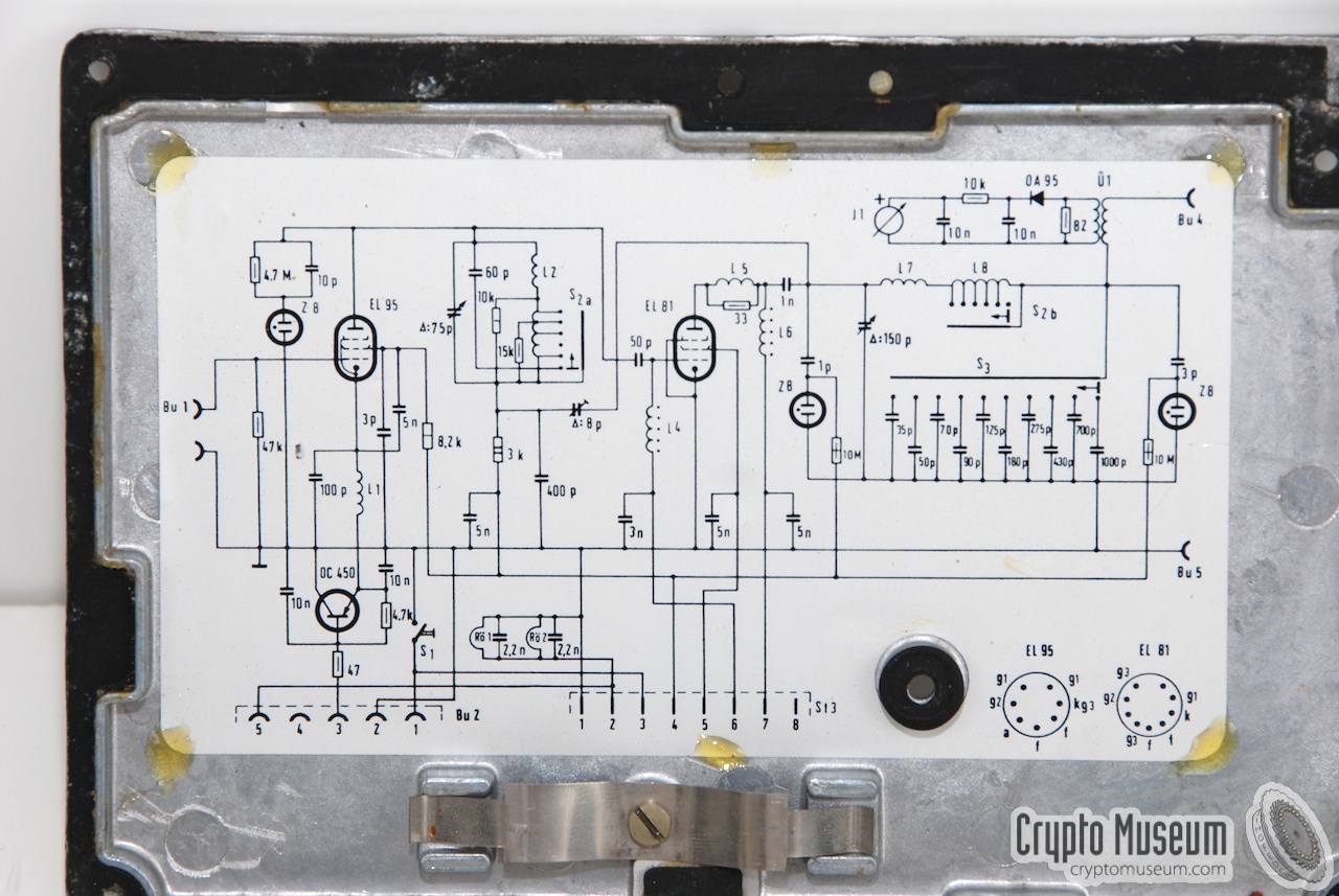
Below is the circuit diagram of the FS-7 transmitter, as it was
recreated from the original one by Karsten Hansky [5] in
May 2015. Click the image for the hi-res version. At the left is
the EL95 oscillator valve. Note that the kathode is keyed by means
of an OC450 silicium transistor. The right half of the diagram is
the Power Amplifier (PA) built around an EL81 valve. Note the two neon
lights and the antenna current meter, all of which are used for
maximum power tuning.
|
|
In the mid-1970s, the Dutch Stay-Behind Organization O&I
(Operatiën en Inlichtingen, eng.: Operations and Intelligence)
ordered the development of an external synthesizer for the FS-7.
The synthesizer was probably built by RACAL and the existing FS-7 units
were modified for this.
|
The modified transmitter became known as the FSS-7.
As far as we currently know, The Netherlands was the only country
where a synthesizer was added to the FS-15. Other countries,
such as Germany, moved to the synthesized FS-20 spy radio set
at this stage.
The synthesizer was implemented as a seperate box that was connected
to the other modules by means of a purpose-built black box.
The crystal socket was subsequently removed from the FS-7 and the
hole was closed with a small aluminium panel, as shown in the image
on the right.
|
|
|
According to documents found in the Dutch National Archives [3],
160 synthesizers were ordered (100 for the I-department and 60
for the O-department) in 1974 for a total amount of 2 million
Dutch Guilders (more than 900,000 Euro).
This breaks down to 5600 Euro for a single unit.
|
Although the name of the manufacturer is not revealed in the
document [3] (parts of it are still classified) it is likely that
the synthesizer was developed and built by RACAL in the UK.
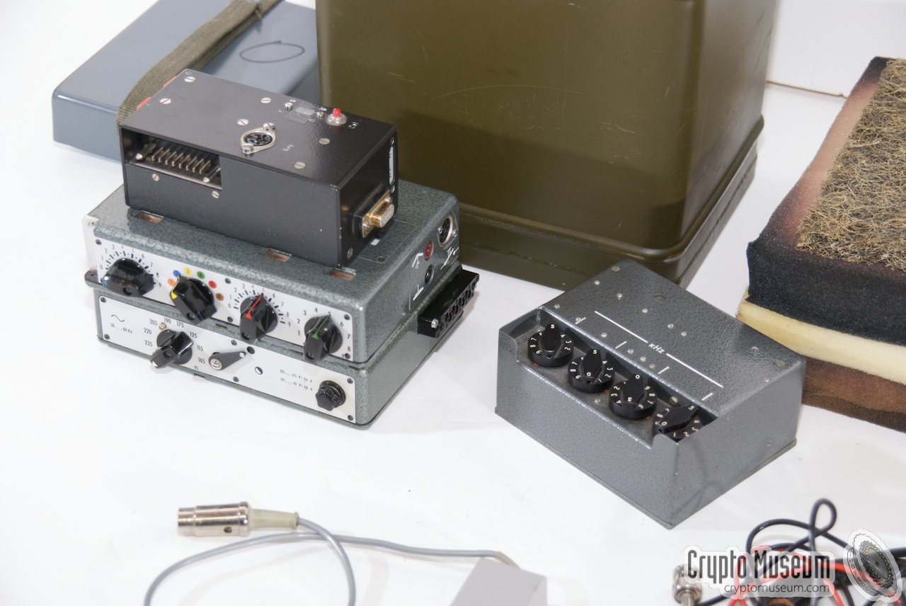
The image on the right shows the synthesizer that was found inside
the SP-15 container that is now in the collection of Museum Jan
Corver [4].
It is constructed in such a way that it can be plugged straight
into the black box that combines all modules,
by means of a 9-pin male sub-D connector (DE9) at the back.
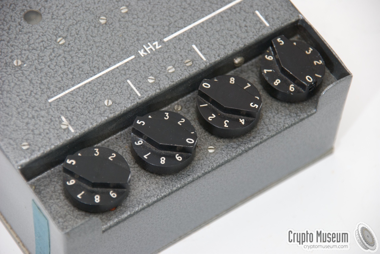
At the front are four recessed dials with 10 positions each.
|
|
|
This way, the frequency of the FSS-7 transmitter can be set in kHz.
A few years later, approx. 1976, the SP-15 and hence the FS-7
was replaced by a fully digital spy radio station, also manufactured
by Racal, known as the PRM-4150.
This suitcase-based transceiver was used as a gap-fill solution
until it was finally replaced by the
FS-5000 (Harpoon) in the early 1990s.
➤ More about the Dutch version
|
-
Document kindly provided by Jim Meyer [1]
|
- Helmut 'Jim' Meyer, HS0ZHK, My way to Ham - Radio and beyond
Website QRZ.COM. Personal correspondence.
Retrieved April 2013.
- H. Pfitzner, FS-7 Circuit Diagram
Date unknown.
- Geschiedenis van de Sectie Algemene Zaken, Hoofdstuk VI, Consolidatie
History of the Section General Affairs, Chapter 6, Consolidation (Dutch).
Dutch National Archives. Top Secret. Partly declassified in 2007
under the FOI Act.
p. 80.
- Museum Jan Corver, Complete SP-15 set in water-tight container
Photographs taken during the exhibition
Secret Messages.
Crypto Museum, October 2008.
- Karsten Hansky, FS-7 Circuit Diagram
Recreated from original diagram. May 2015.
|
|
|
|
Any links shown in red are currently unavailable.
If you like the information on this website, why not make a donation?
© Crypto Museum. Created: Sunday 20 September 2015. Last changed: Monday, 14 September 2020 - 08:55 CET.
|
 |

|
|
|