|
|
|
|
|

|
|
RX Germany BND SBO W&G BND ← SP-20 ← SP-15
The BN-58 is one of the first small receivers that was fully
transistorised and was characterised by a very low power consumption.
The double conversion superheterodyne receiver has an
IF1 of 1.635 MHz and covers 2.5-24 MHz divided over two bands,
selectable with a knob at the front.
The receiver features permeability tuning (coil tuning), similar to
Collins receivers, that allows the scale to be virtually linear.
There is a separate tuner for each of the two frequency bands.
The device is powered by an internal 6V NiCd battery or by an external 6V
DC power source.
|
|
|
|
The receiver was originally designed for use with the
SP-15 spy radio set. It has a connection at the rear that can
be connected in parallel to the morse key of the FS-7 transmitter,
in which case the receiver provides the side-tone during transmissions.
When the SP-15 was succeeded by the SP-20, around 1970,
it appeared to be difficult to develop a new digital receiver that had at
least the same sensitivity as the BN-58.
It was therefore decided to re-use the old BN-58 as part of the new
SP-20 spy radio set. This is why there are fewer surviving BN-58
units than spy radio sets.
|
-
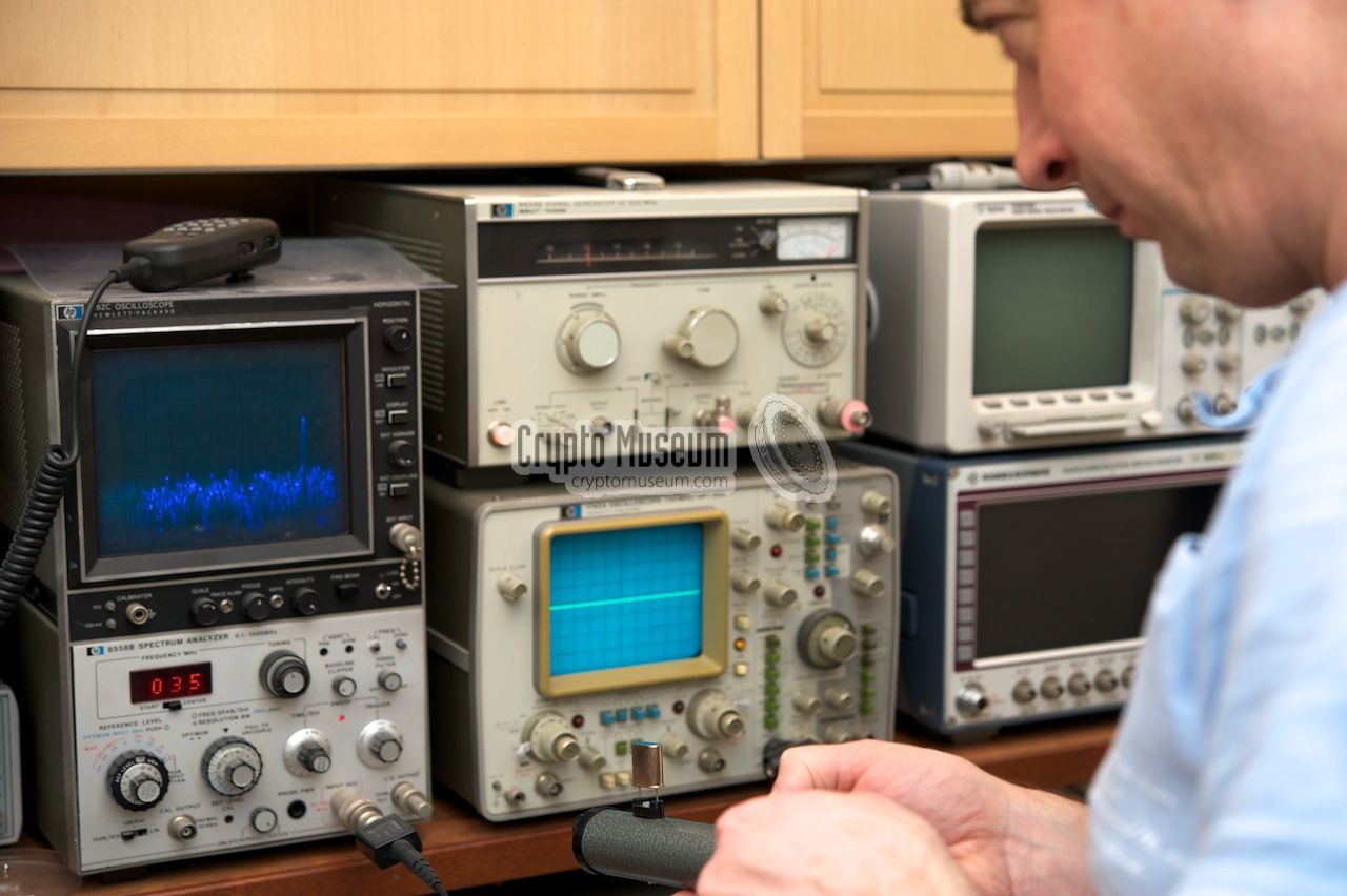
W&G was widely known for the production of high-end electronic
test equipment, such as audio and HF spectrum analyzers.
➤ More
|
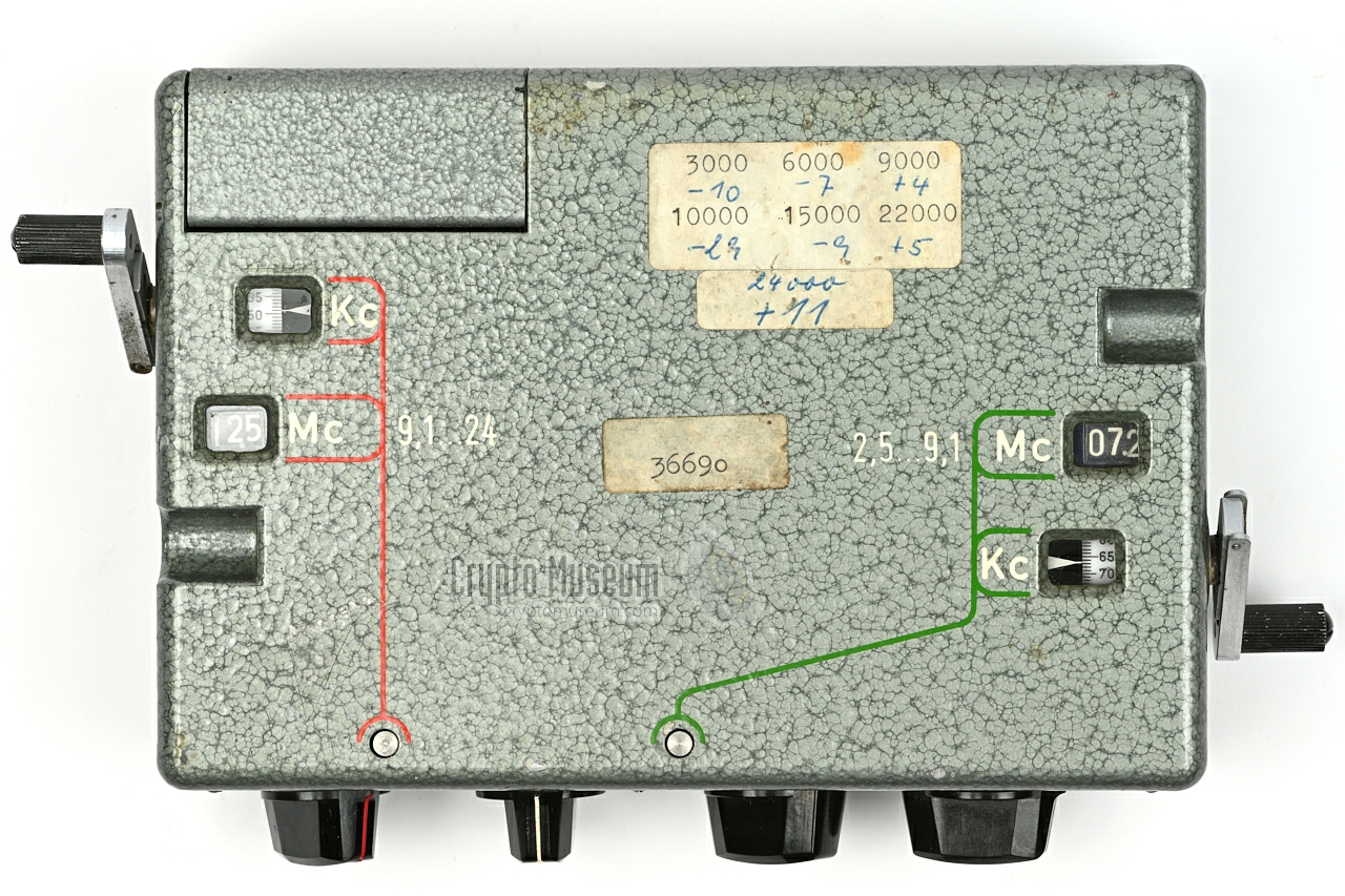
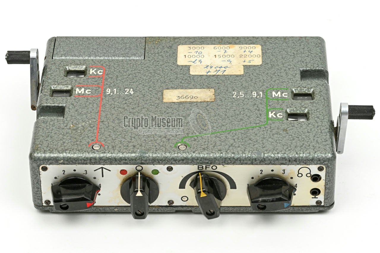
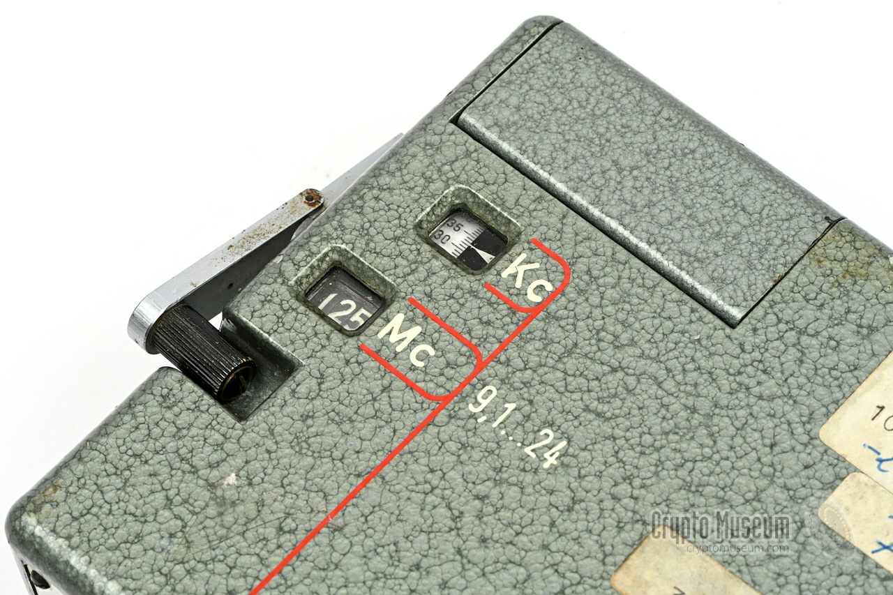
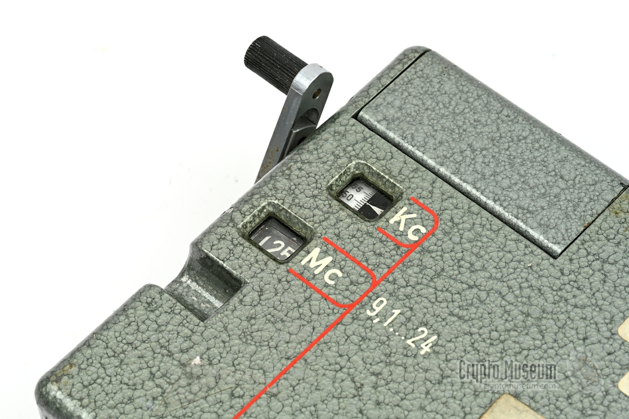
The image below provides a quick overview of the control of the FE-8 (BN-58).
It is powered by an internal 6V rechargeable NiCd battery, or by an
external 6V DC power source that is connected to the 2-pin LEMO socket at
the rear. It is turned on by setting the band selector either to band 1 (green)
or band 2 (red). Setting the band selector to the centre postion (white) turns
it off again.
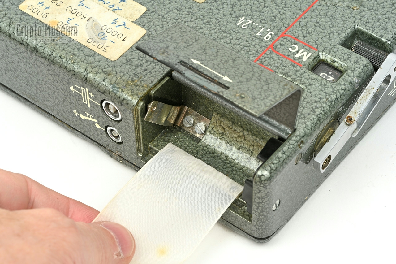
Antenna and ground wires are connected to the recessed banana sockets at the
left side. An earpiece or a pair of high impedance headphones
(2000 Ω)
is connected to the 2-pin socket at the right edge of the front panel. Depending
on the selected band (1 or 2), the foldable crank at the right or left should
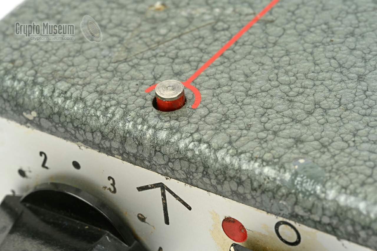
be used respectively. A metal stub is raised from the top surface to show
which band is currently selected.
The leftmost stub is raised when band 2 (red)
is selected.
|
Below is the block diagram of the FE-8 receiver, based on the
work of Helmut (Jim) Meyer (DJ2EI) [1].
At the left are the two different tuners (one for each frequency range).
The first local oscillator and mixer are inside the tuner and produce
an IF1 at 1.635MHz. This signal is mixed with a 2nd IF oscillator
at 1.180 MHz. It produces a 455kHz IF2 signal that is amplified
and fed to a detector. The output of the detector is amplified to a suitable
level for 600-4000 Ω headphones. For the reception of CW
(morse),
the signal of a switchable and adjustable BFO is mixed with the 455kHz
signal in the 3rd IF amplifier.
In the leftmost position of the BFO-knob, the BFO is turned off.
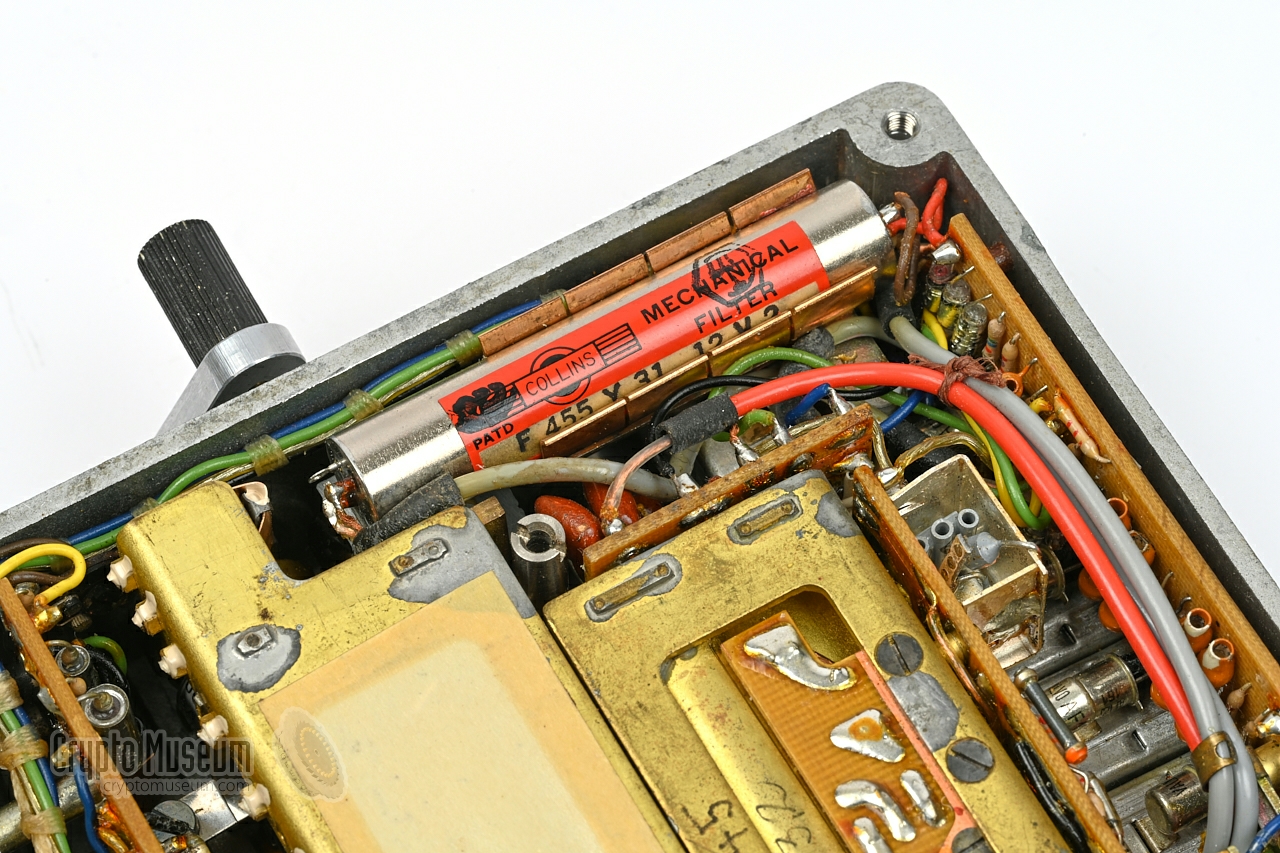
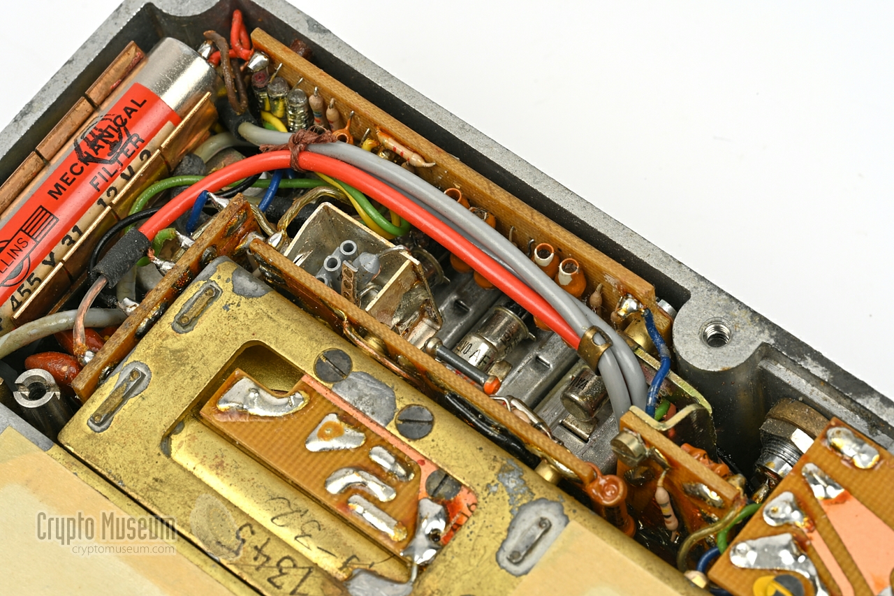
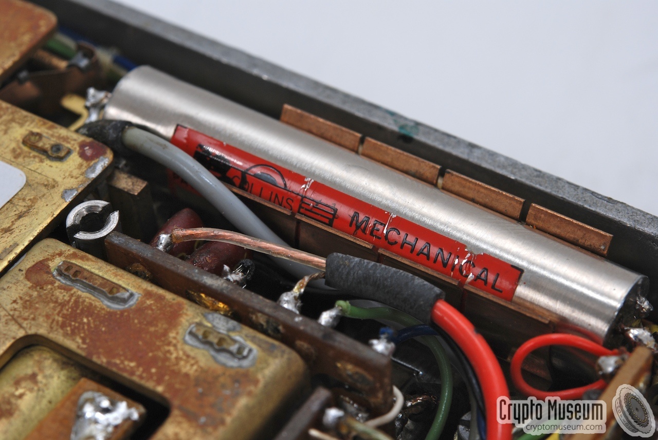
The filter between the 2nd mixer (IF2) and the IF amplifier
is a mechanical Collins band-pass filter
which is just 3.1 kHz wide.
In the above block diagram, the two tuners are each simplified to a single
block. A more detailed block diagram of a single tuner is given below.
|
|
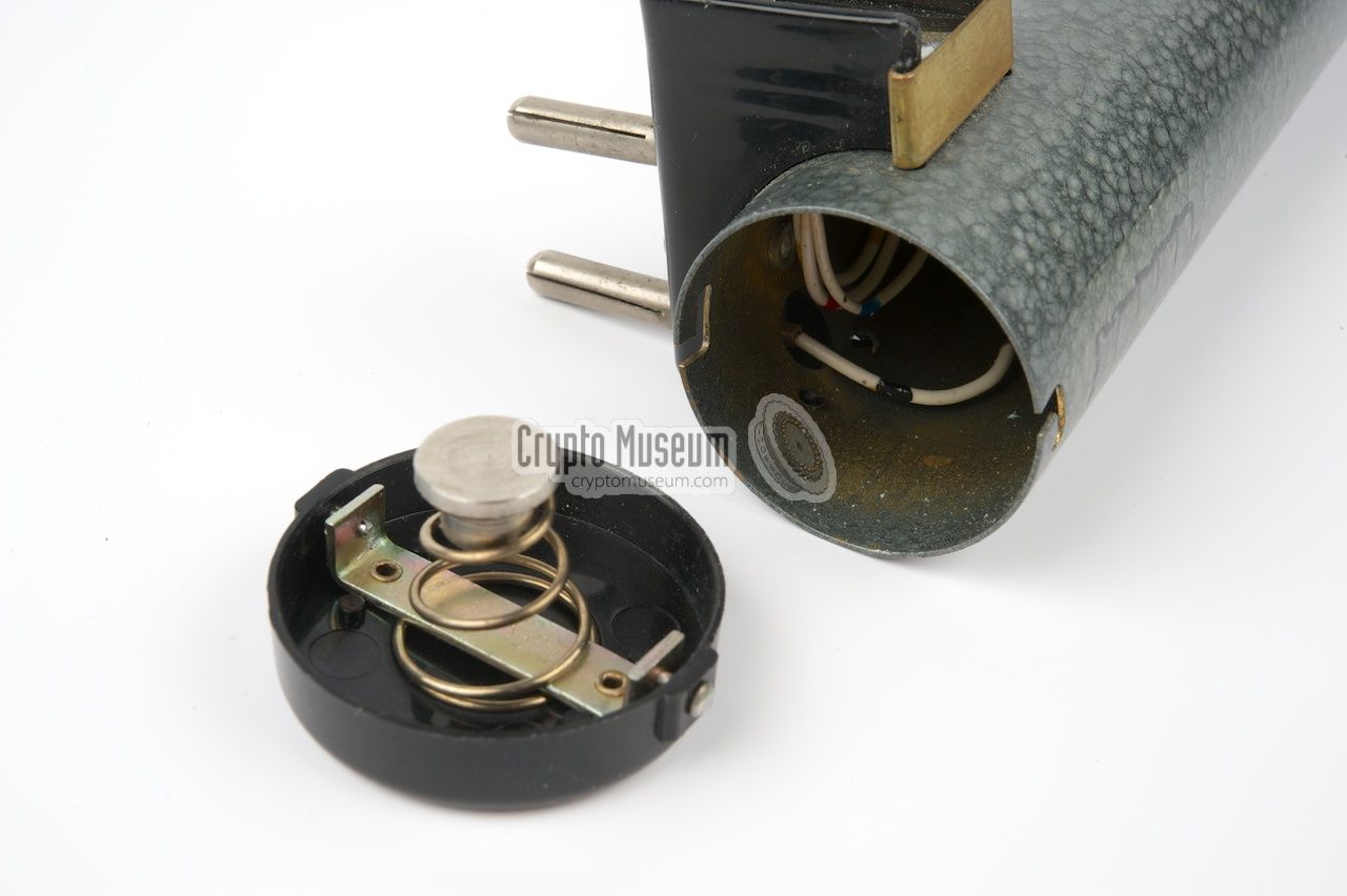
The FE-8 can be powered by an internal 6V battery,
that consists of five stacked 1.5V NiCd cells. As the original battery is
no longer in production, it may be difficult to find a replacement.
It should be relatively easy however to create a good alternative
from existing 1.2V NiMH cells.
Suitable replacement batteries are now readily available from
Akkuumbau
in Germany [5].
|
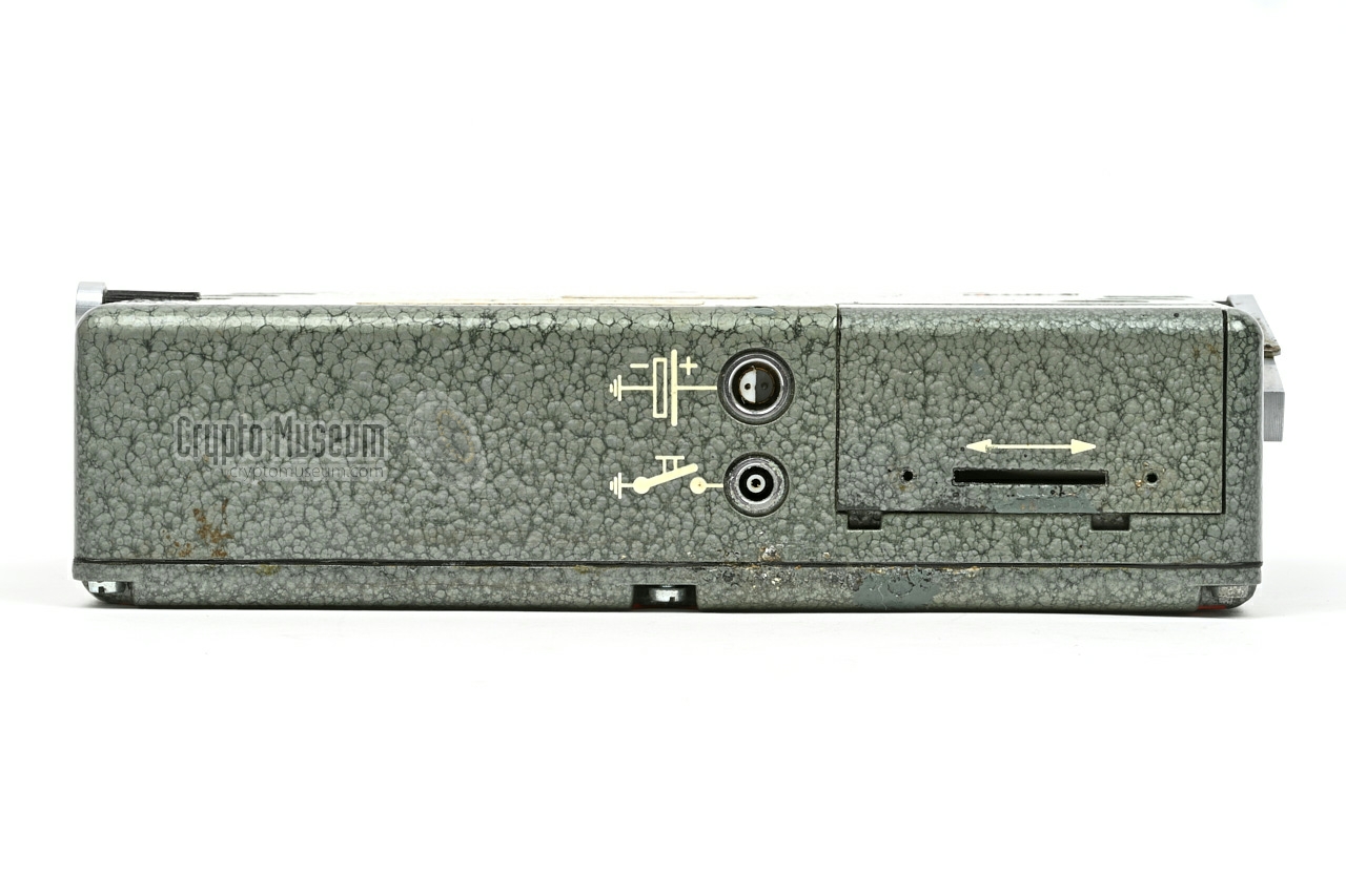
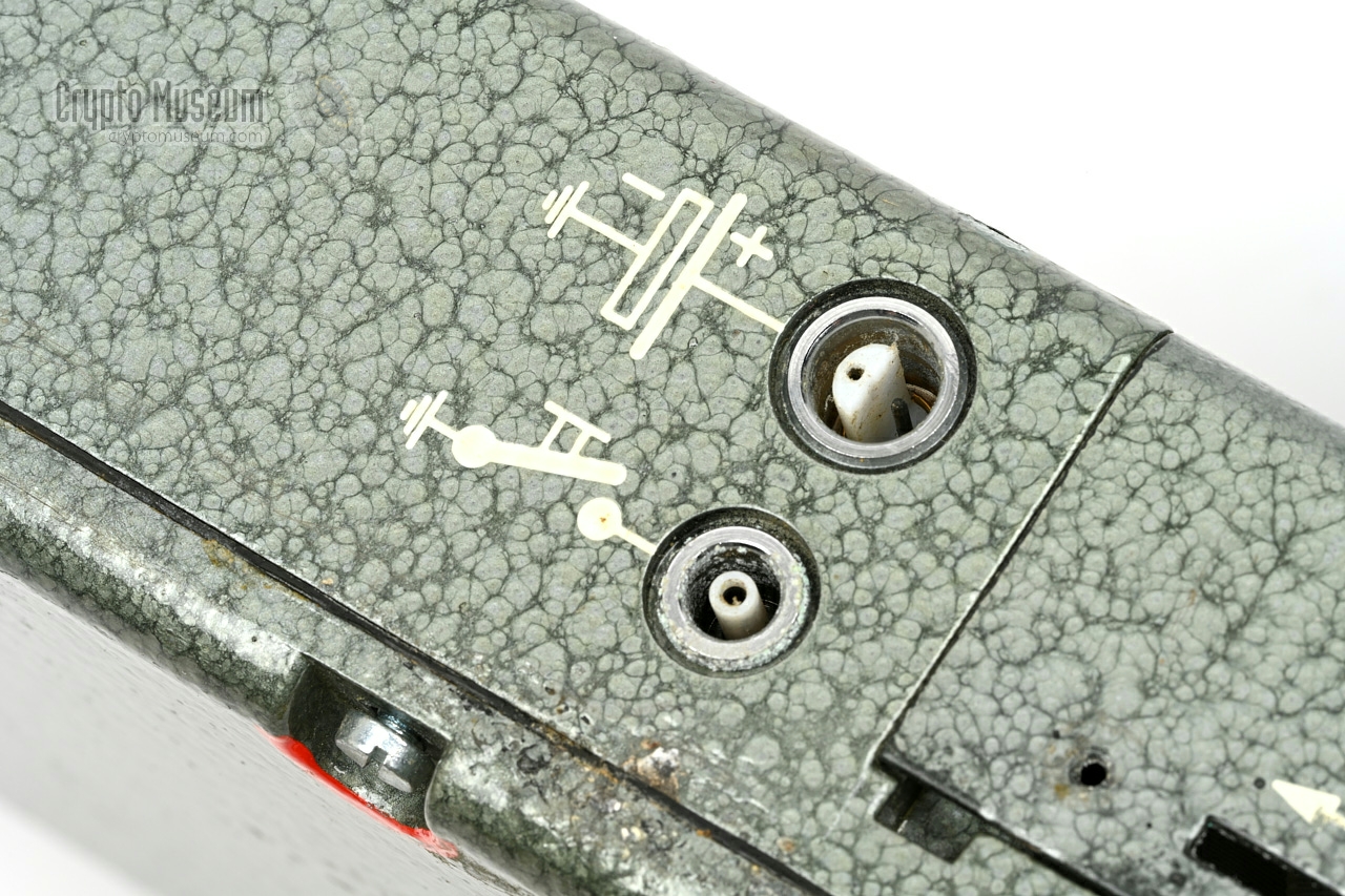
The FE-8 can also be powered from external 6V DC source that should
be connected to the power socket at the rear of the device, close to
the battery compartment. This sockets needs a
2-pin LEMO connector
of which both pins are used for the plus connection, whilst the
shield is used for the ground (negative) contact.
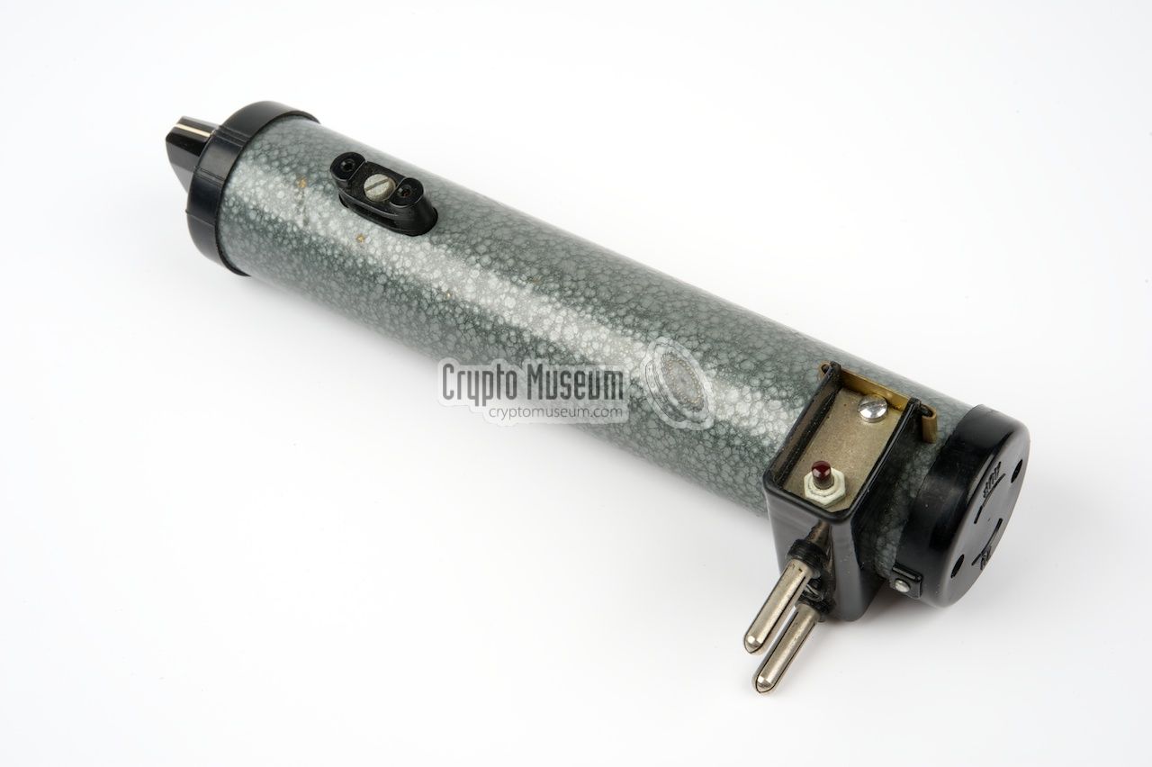
The image on the right shows the charger that was
supplied with the FE-8. It allows the 6V battery to be charged directly
from the 220V AC mains. The battery is placed inside the outer shell,
which is then fitted onto the charger.
|
|
|
|
The complete assembly can then be inserted into a standard wall socket.
Once the battery is full, it can be placed inside the battery
compartment of the FE-8 again. Alternatively, the battery can be charged
directly inside the FE-8 by supplying a slightly higher voltage (7.2V)
to the external DC socket at the rear.
The same type of 6V stacked battery is used in the calibrator
(see below).
|
|
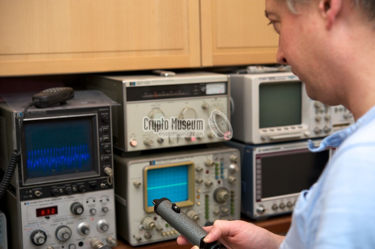
The BN-58 was a very sensitive receiver with a nearly linear scale,
making it easy to tune it to the desired frequency.
Nevertheless, it had to be calibrated from time to time.
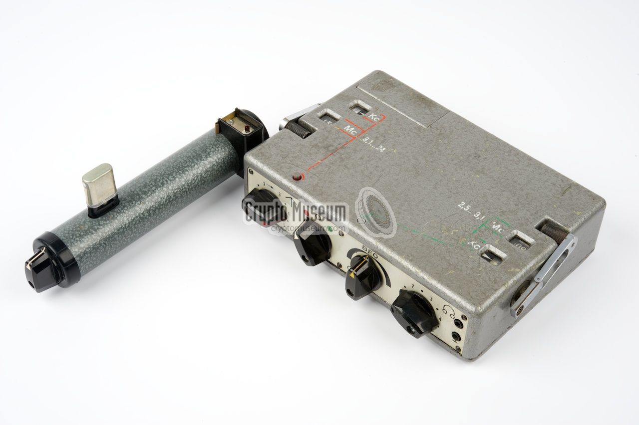
This was done by means of the external calibrator shown
in the image below, which is in fact a frequency marker.
|
Inside the device is a so-called comb generator [4]; a device
that generates multiple harmonics from a single base frequency,
all of which are identical in strength. When used with a rounded
base frequency (e.g. a 1 MHz crystal) it produces a reference signal (marker)
at regular (1 MHz) intervals. The device is constructed in such a
way that its signal is rather weak (typically -60dBm or lower),
so that the sensitivy of the receiver can be checked at the same time.
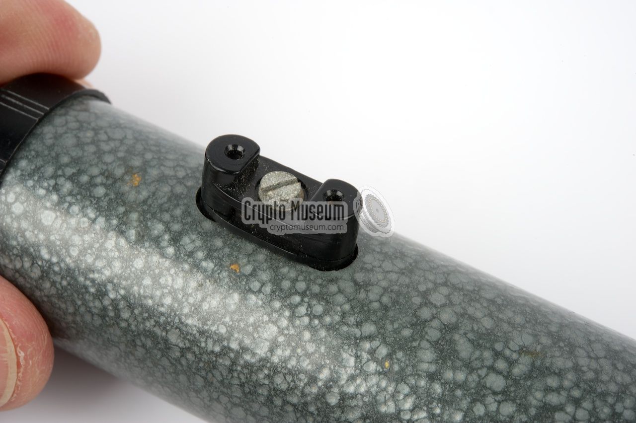
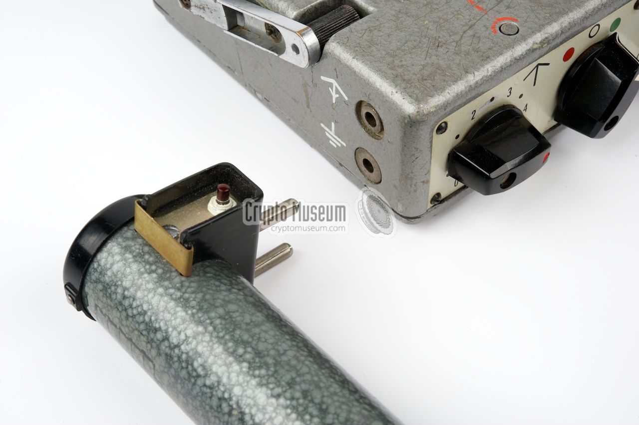
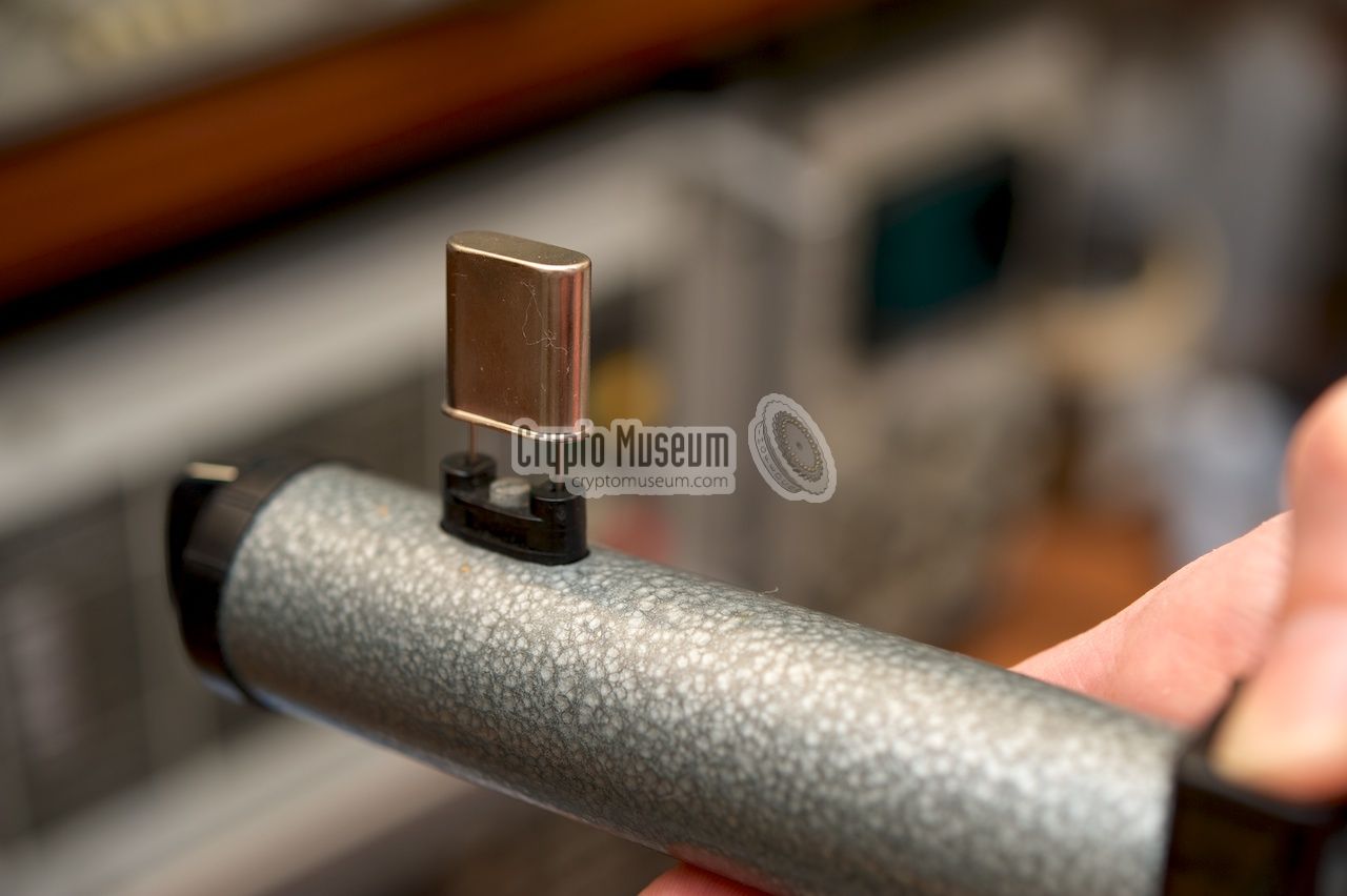
The device has two internal reference crystals plus an external one
that can be inserted in the crystal socket on top of the device.
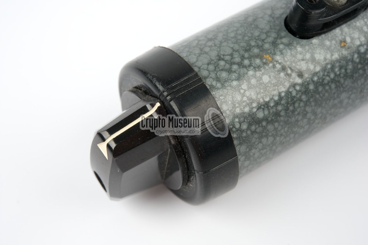
At the front is a three-position rotary switch
with three settings, marked I, II and III.
It is used to select the mode of operation:
|
- 100 kHz
This setting produces a -80dBm marker signal
at 100 kHz intervals.
- 1 MHz
This settings produces a -60dBm marker signal
at 1 MHz intervals.
- Crystal
In this mode, the external crystal socket on top of the device is used.
It can be used with any arbitrary frequency that is within the range
of the receiver. We've tried, for example, a standard amateur frequency
crystal of 3.575 MHz, which generates
a marker at 3.575 MHz, 7.150 MHz, etc.
In this mode, the signal strength depends on the crystal's activity.
|
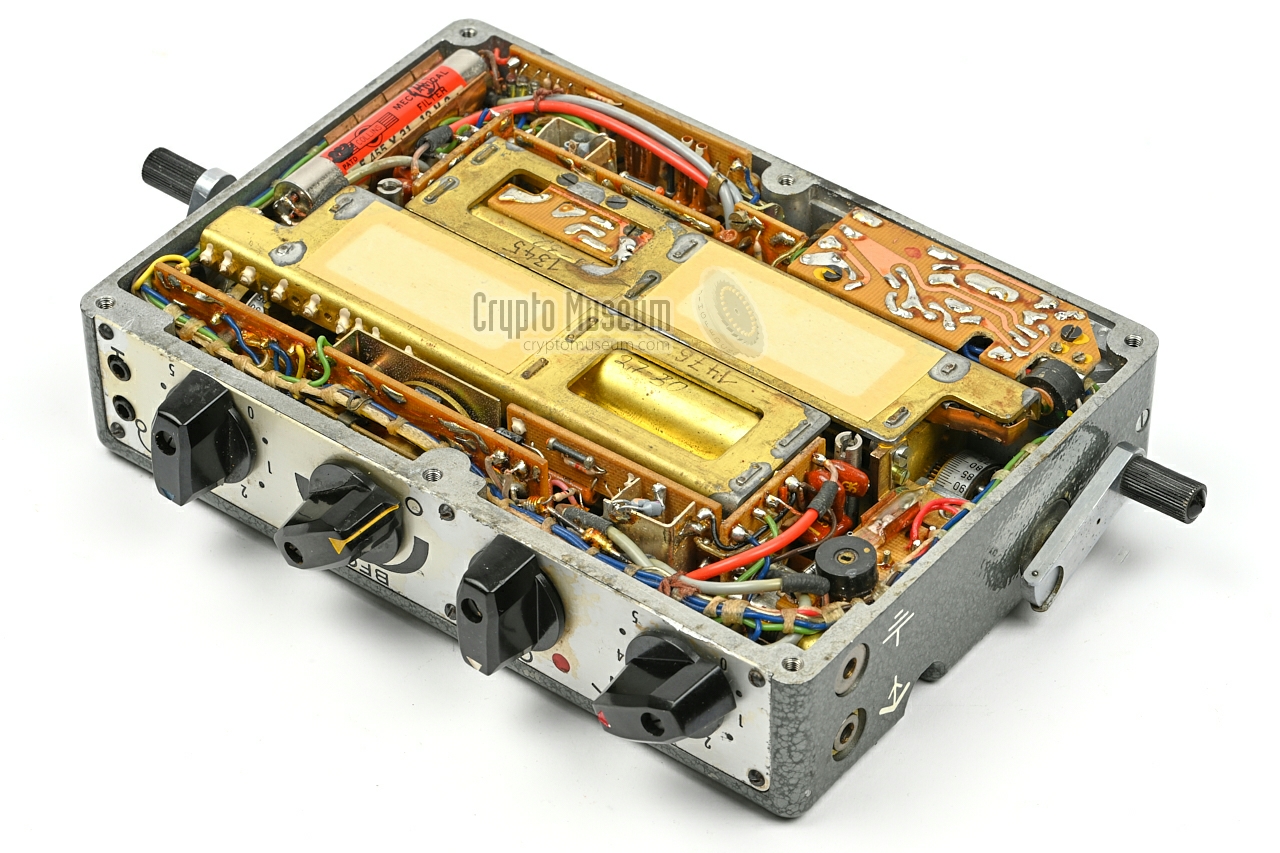
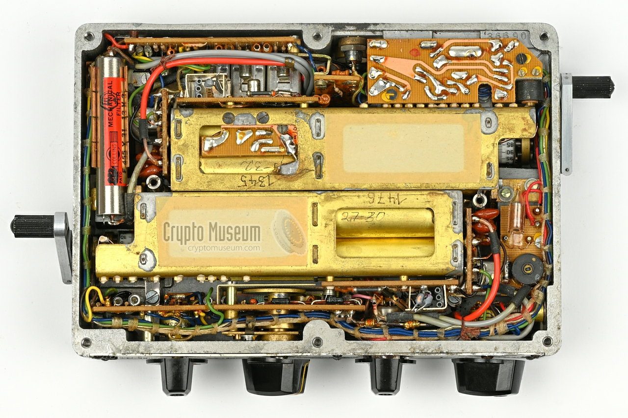
The FE-8 is housed in a die-cast aluminium enclosure that measures
184 (210 when in use) × 130 × 45 mm and weighs little over 1.5 kg.
The interior can be accessed by removing 6 screws from the bottom,
after which the sealed bottom panel can be taken off. This reveals the
two permeability tuners (variometers) and additional electronic PCBs,
as shown in the image below.
The receiver is not very service friendly, as most repairs
require a nearly complete disassembly of the device in order
to access the components on the various PCBs. To illustrate this,
the image below shows a BN-58 of which Variometer 1 has been
removed. Note that the oscillator and the first mixer are
mounted to the variometer. The construction of Variometer 2 is nearly
identical. Note that the 2nd IF stage (rear), the BFO and the
AF circuits (front) are common to both bands.
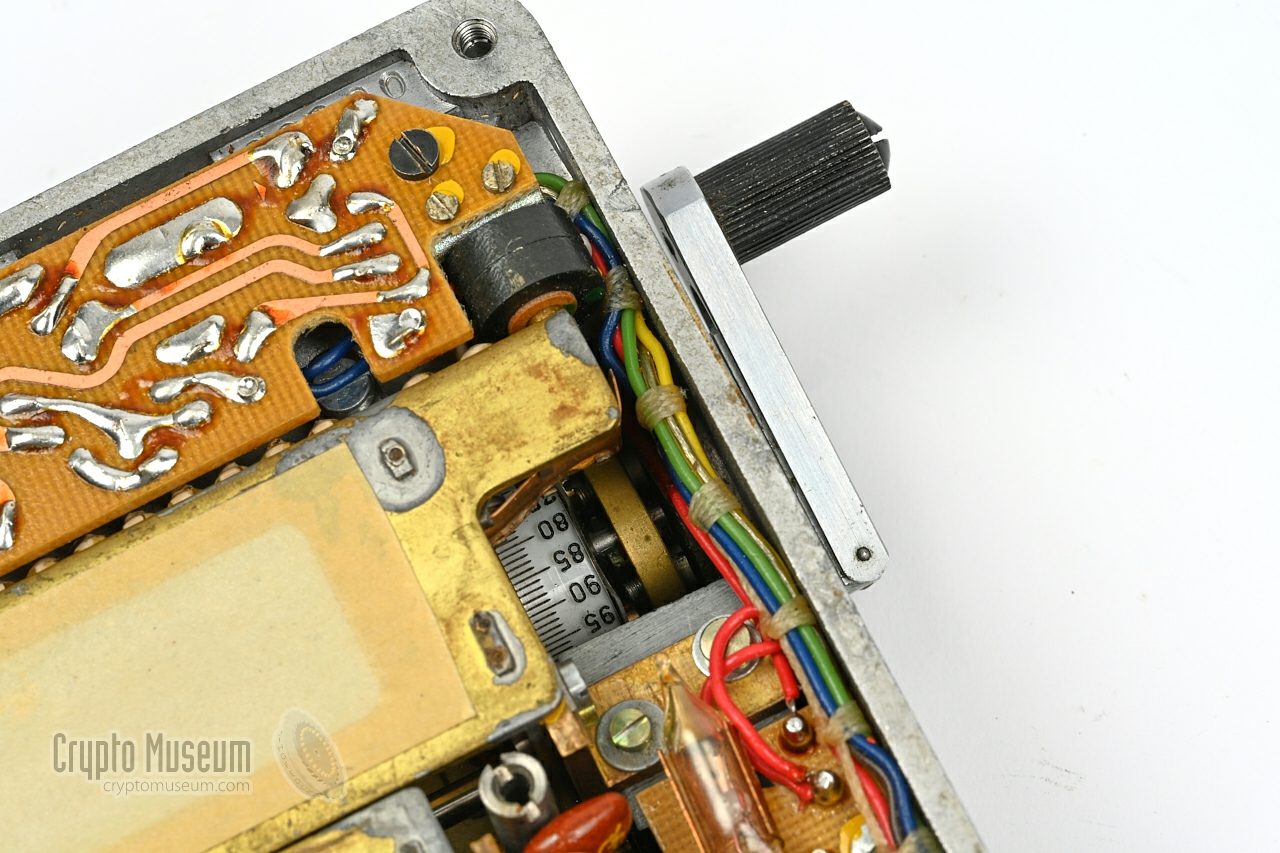
|
The two tuners are highly complicated devices with multiple permeabilty
tuning coils, resulting in a nearly linear tuning scale. Turning the
crank moves the ferrites in and out of the coils.
In order to eliminate any linearity errors, a sophisticated
adjustment-correction mechanism is present, as shown in the images
below. It comprises a number of tuning points and a lever that senses
the correction curve formed by these tuning points.
Never alter the adjustments of the tuning points.
Permeability tuning was a special feature of the BN-58 that was not commonly
found in other clandestine receivers of the era, except for the contemporary
RR/E-11 which has a very similar construction.
Nevertheless it wasn't new, as it was already used during WWII in the
American RBZ Receiver.
In the 1960s, permeability tuning was also
used in some early car radios.
|
Device Portable short wave receiver Purpose Clandestine agent-centre communications Model BN-58 Designator FE-8 Year 1958 Manufacturer Wandel & Goltermann Part of SP-15, SP-20 Principle Double conversion superheterodyne Frequency 2.5 - 24 MHz Bands 2 (see below) Modulation AM, CW IF1 1.635 MHz IF2 455 kHz Output 600-4000Ω (typically: 2000Ω) Power 6V DC Dimensions 184 × 130 × 45 mm (210 × 130 × 45 mm when in use) Weight 1508 g
|
Green 2.5 - 9.1 MHz Red 9.1 - 24 MHz
|
- FE-8
- BN-58
- SP-20E
- Empfänger SP-15
- Kurbelempfänger (crank receiver)
|
-
Document kindly provided by Jim Meyer [1].
Document kindly provided by Günter Hütter 6.
|
|
|
|
Any links shown in red are currently unavailable.
If you like the information on this website, why not make a donation?
© Crypto Museum. Created: Monday 03 August 2009. Last changed: Wednesday, 07 January 2026 - 21:42 CET.
|
 |

|
|
|


