|
← Germany WWII Abwehr
Abwehr spy radio set · 1942
- this page is a stub
SE 108/10 and SE-110/11 1 are both designators of a
clandestine transmitter and receiver,
also known as a spy radio set, developed during WWII,
in 1942, by OKW-Aussenstelle Wurzen 2
and manufactured at Nischwitz Castle (Germany),
for use by the German Intelligence Service,
the Abwehr [1].
The set consists of three small units in tin enclosures,
and is often referred to as the Keksdosen (Biscuit tins).
It was produced alongside the less powerful single-unit
SE-109/3.
The image above shows the complete set, in the bottom section of a storage
cassette. From left to right are receiver (RX), power supply unit (PSU),
and transmitter (TX). The three units are interconnected by means of
4-pin Brechkupplungen (break connectors),
so that the set can be used without
removing it from the cassette. At the front of the transmitter is a miniature
morse key, that can be stowed inside the transmitter's enclosure
(otherwise the cassette can not be closed).
The mains power cable is hidden inside the PSU. To access it, the
top lid of the PSU has to be removed and must stay off as long as the PSU
is connected to the mains, as there is no hole to feed the cable through. This
was probably done to ensure sufficient cooling.
➤ User manual
|
 |
-
In Louis Meulstee's book Wireless for the Warrior Volume 4, the SE-108/10
is referred to as SE-100/11 [1]. Both names are believed to be correct.
-
OKW = Oberkommando der Wehrmacht (Supreme Command of the Armed
Forces, or German Army High Command) in Nazi Germany during the
Second World War. Aussenstelle = Outpost.
-
Note that different frequency ranges were used for specific missions [1].
|
- SE 108/10
Initial version of 1942 of which the transmitter was built around an
EL2 valve (tube),
which produced an output power of 10W.
This comprises all units up to serial number 100.
- SE 100/11
Due to wartime shortages, the EL2 was replaced in 1942/43
by the UBL21,
which was more common and was readily available at the time [4].
For this, the PSU was changed as well.
It affects sets with serial number from 100 onwrads.
|
It is believe that both model numbers refer to the same set.
In addition there are many manufacturing variations, which may
have been caused by supply shortages. There are also variants with a
different frequency range, as this was usually tailored to a specific
Abwehr radio net.
|
In the mid-1990s, an SE-100/11 with serial number 268 was found in Finland,
together with radio instructions and cipher material for a so-called
Sonderkommando Nord (special command north) radio station named 'Land'.
The cipher material consisted of two plexiglass Caesar Discs.
The image above shows the original plexiglass cipher discs, as found
with the SE-100/11 in Norway. In 1996, Finnish radio amateur Esko Jokinen
(OH3QS) made a detailed description of their construction and use, based on the
documentation that had been found with the set [5].
The current whereabouts of this radio set and the cipher discs are unknown.
➤ Description of cipher discs
|
The SE-108/10 consists of three same-size tin boxes that are interconnected
by means of so-called Brechkupplungen (break-connectors). The image
below shows the three units after the top lids are removed. From
left to right: receiver (RX), power supply unit (PSU) and transmitter (TX).
|
Below is the circuit diagram of the transmitter, as it appears in Louis
Meulstee's book Wireless for the Warrior Volume 4 [1].
There are two versions of the circuit. Transmitters up to serial
number 100 were built around an EL2 valve. It is likely that this
version was known as SE-108/10.
Due to supply problems during the second half of the war, this valve was
replaced by the more common UBL21, which needs a 55V filament voltage.
It produced a slightly higher output power (11W instead of 10W) and it is
likely that this version was designated SE-100/11. Note that this version
needs a different power supply unit (PSU) than the SE-108/10, as the voltages
for the transmitter are different. The diagram below shows the circuit
of the S100/11 transmitter.
|
| |
S-100/11 transmitter circuit diagram
|
|
|
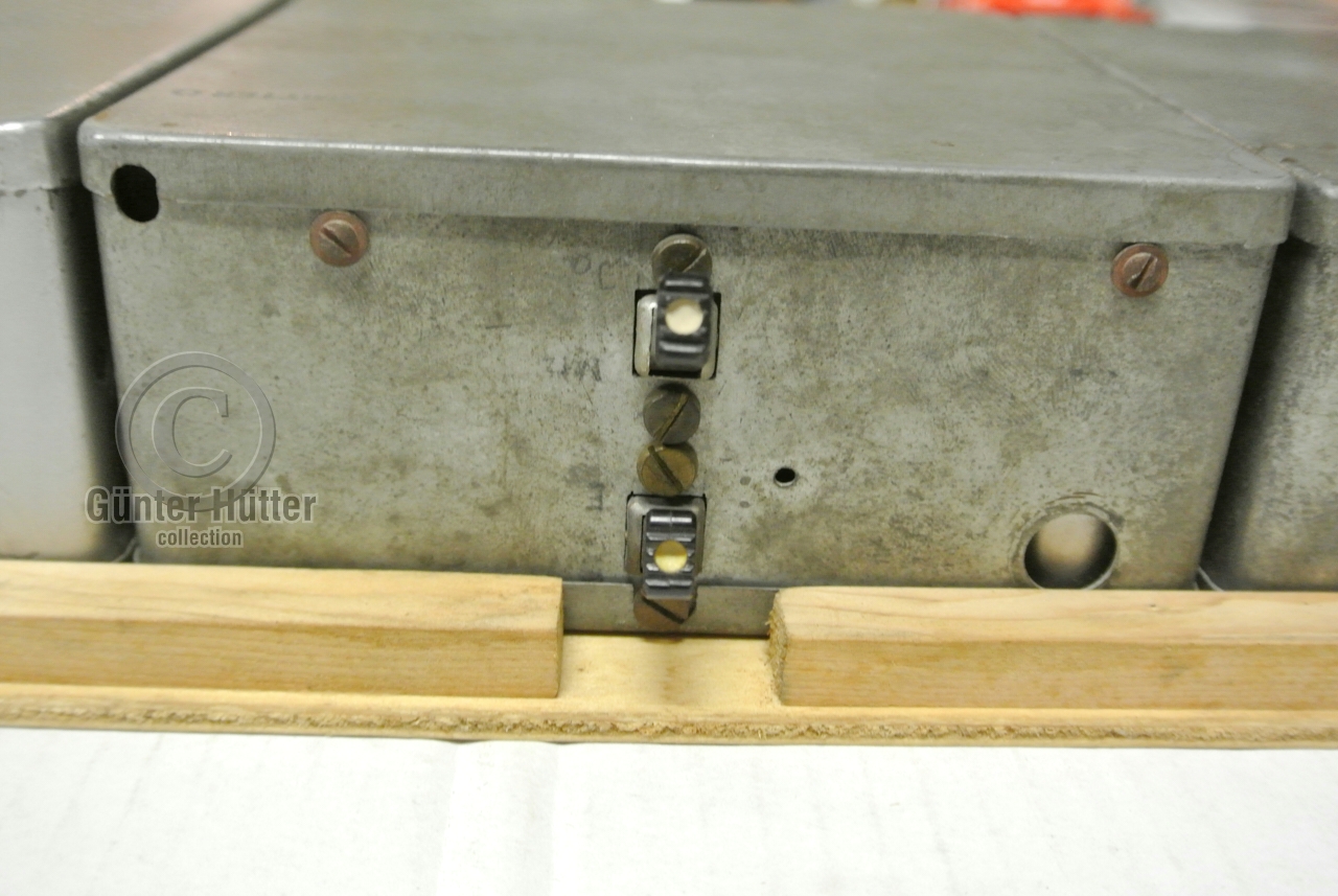
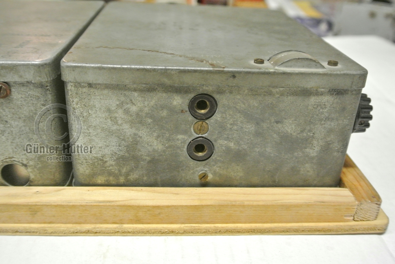
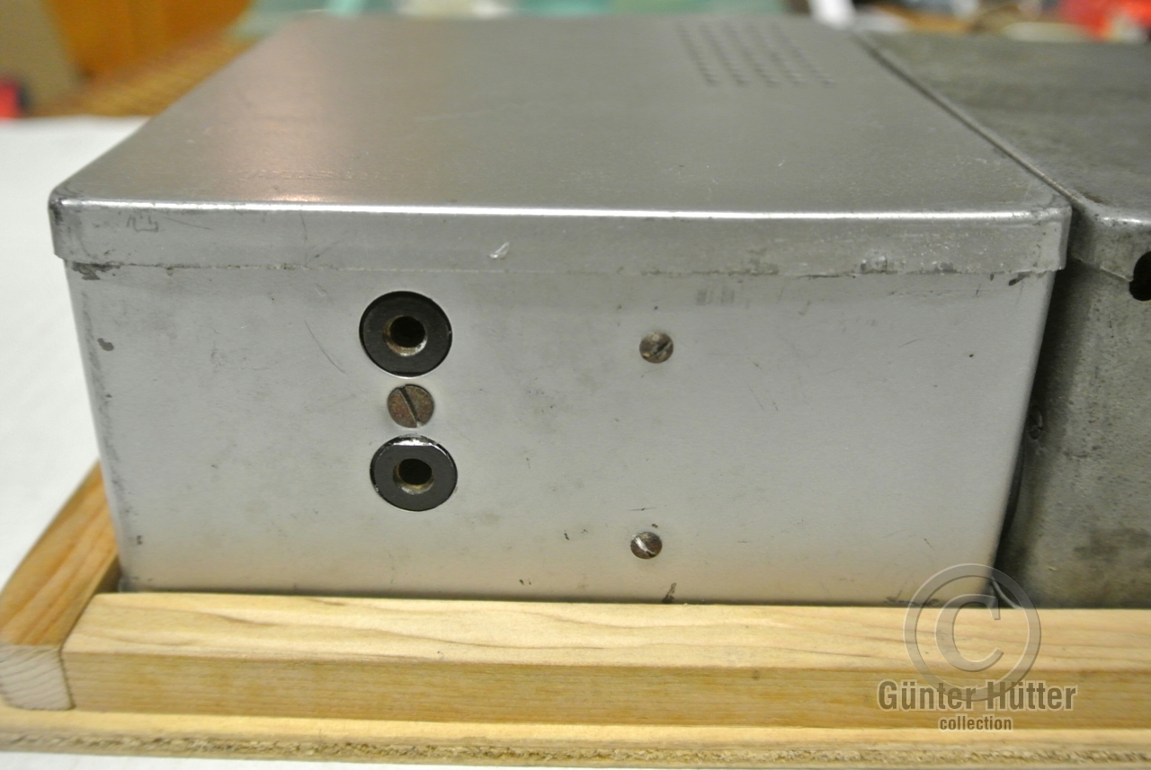
Power is distributed between the three units, by means of 4-pin circular
connectors that are known as break connections
(German: Brechkupplungen). These connectors were also used by the German
Air Force during WWII.
Below is the pinout when looking into the male socket.
|
- HT 237V DC
- Meter
- GND 0V
- LT 55V AC
|
|
- HT 170V DC
- LT GND (connected to 3)
- HT GND (connected to 2)
- LT 6.3V AC
|
|
IMPORTANT —
Note that the notch in the socket can be at the bottom (as shown here)
oas well as at the top. This is not related to the layout of the wiring though.
It is unclear why the notch on some devices was at the opposite side.
If transmitter and receiver are used with the original PSU, this should
not be a problem.
 |
|
EL2 transmitter valve
S/N up to 100
|
|
|
Initially, the transmitter was built around an EL2 valve that produced an output
power of approx. 10W. It's anode (HT) is powered at 237V DC, whilst the
filaments (LT) are powered by 6.3V.
➤ EL2 datasheet
|
|
|
UBL21 transmitter valve
S/N 100 onwards
|
|
|
As the EL2 was in short supply during the war, the set was redesigned and
the EL2 was replaced by an UBL21, which has similar specifications, but was
much easier to obtain at the time. The only problem was that the UBL21 needs
55V for its filaments, for which the PSU was changed as well.
➤ UBL21 datasheet
|
Device Modular spy radio set Manufacturer OKW-Aussenstelle Wurzen Customer Abwehr Year 1942
|
S/N < 100 Bands 2 Frequency (1) 300 kHz - 6.2 MHz 1
(2) 6.2 MHz - 12 MHz 1 Channels 3 (1 external, 2 internal) 2 Modulation CW Output 10 Watt Valve EL2 Key Internal, external
|
Device Modular spy radio set Manufacturer OKW-Aussenstelle Wurzen Customer Abwehr Years 1942-1943
|
S/N ≥ 100 Bands 2 Frequency (1) 300 kHz - 6.2 MHz 1
(2) 6.2 MHz - 12 MHz 1 Channels 3 (1 external, 2 internal) 2 Modulation CW Output 11 Watt Valve UBL21 Key Internal, external Dimensions 140 × 120 (128) × 62 mm Weight 850 g
|
Dimensions 140 × 120 (128) × 62 (67) mm 3 Weight 950 g
|
Dimensions 140 (155) × 140 (152) × 62 mm Weight 2290 g
|
-
Different ranges are known to exist and depended on area, user and
Abwehr radio network.
-
In some radios, the two internal channels are populated with crystals.
-
Value in brackets is the size including knobs, connectors, scale, etc.
|
102 TX Crypto Museum, Netherlands 105 PSU Crypto Museum, Netherlands 165 RX Crypto Museum, Netherlands 226 All Crypto Museum, Netherlands 272 RX Günter Hütter, Austria 134 761 RX eBay, 19 December 2022 538 642 RX Crypto Museum, Netherlands
|
|


![SE-108/10 in storage cassette, seen from the top. Copyright Günter Hütter [2].](img/GH_SE108_complete_large.jpg)