|
|
|
|
|

|
|
← Rion USSR Cold War PR-56 →
Spy radio transmitter
P-57 is a small valve-based transmitter, developed in 1957 in the former
Soviet Union
as part of the RION spy radio set,
alongside the PR-56 receiver.
The transmitter covers a frequency range from 2.5 to 10 MHz,
both VFO and crystal operated, with an output power of 10W (CW).
The radio set was intended for international espionage and clandestine
operations by the Soviet Union.
|
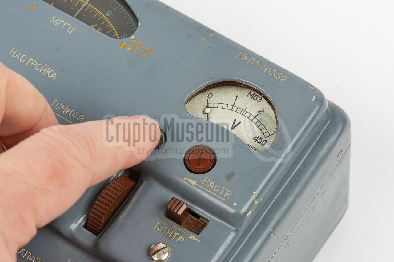
It has the same form factor as the PR-56 receiver and does
not seem to have a model number of its own. The serial number starts with
P570xxx, which suggests that is was purpose built for the P-57 RION
set and that, unlike the receiver, it was not used as part of another
spy radio set.
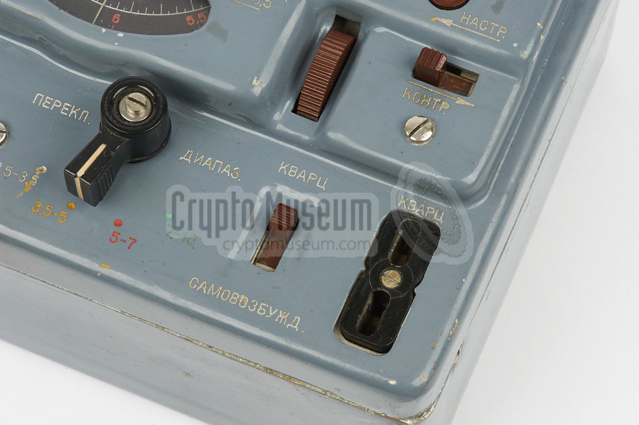
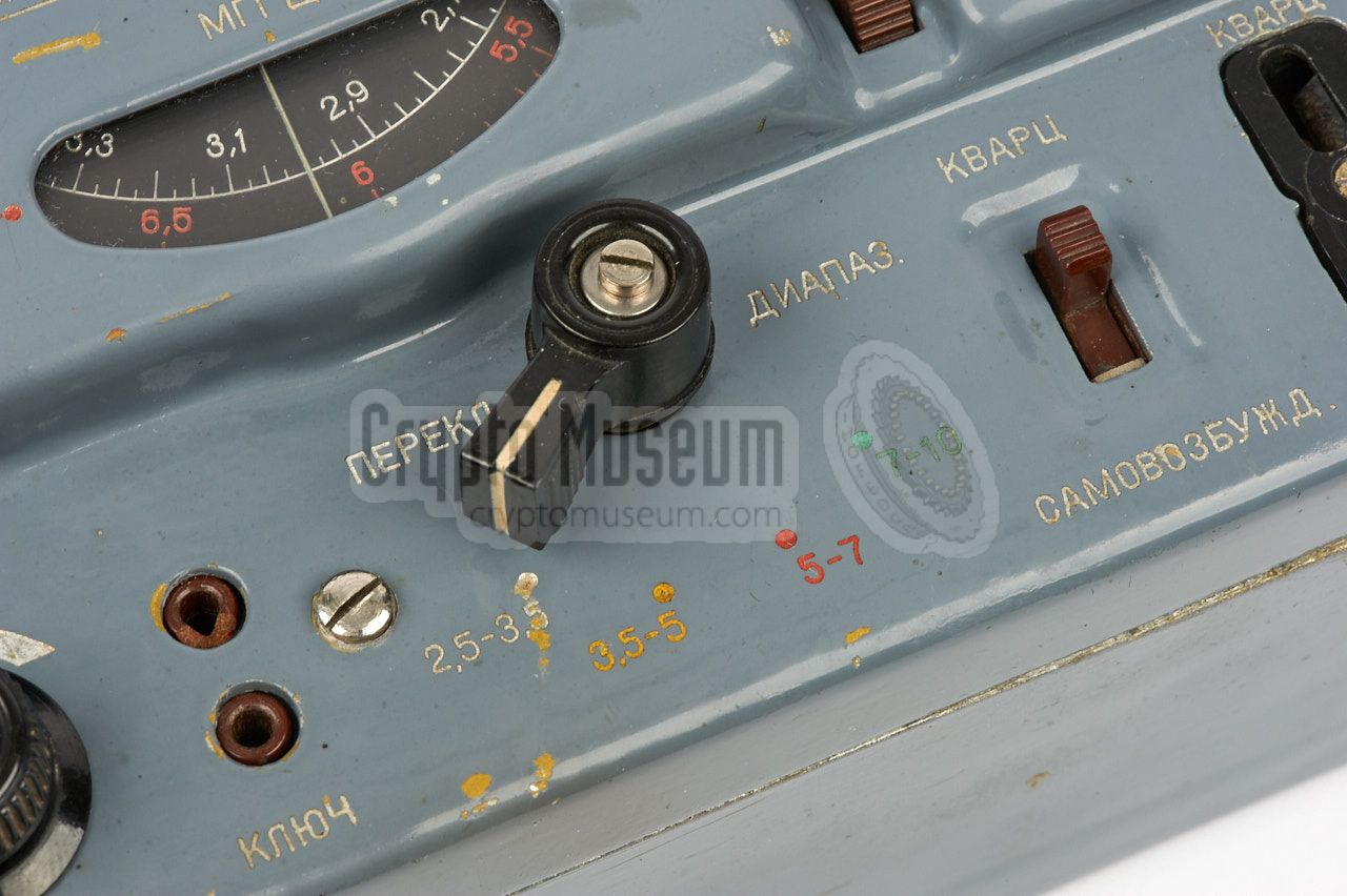
The transmitter's frequency range is divided over four bands, identified
with the colours white, yellow, red and green. The frequency can be determined
by a crystal operating in the 2nd or 3rd overtone, or by the
Variable Frequency Oscillator (VFO), selectable by a slide-switch.
|
|
|
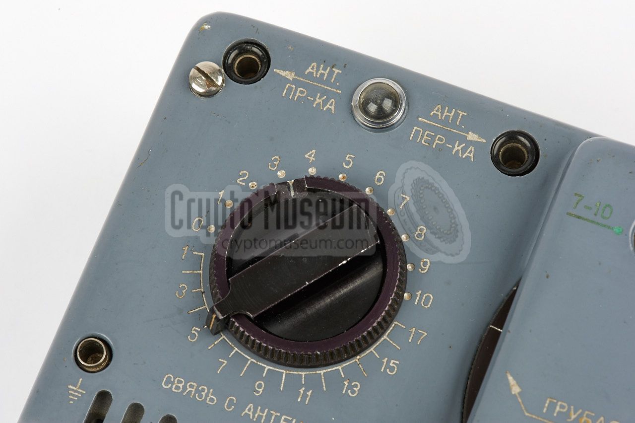
A suitable wire antenna should be connected to the antenna socket,
to the left of the frequency scale. At the top left is an antenna output
that should be looped to the receiver. When enabling the transmitter,
an internal relay switches the antenna from the receiver to the transmitter.
A suitable counterpoise should be connected to the ground socket at the
left centre. The antenna tuner at the top left should be used to tune for
optimum performance, using the table on the top lid of the accessory box.
A morse key is connected to the 2-pin socket at the front centre.
|
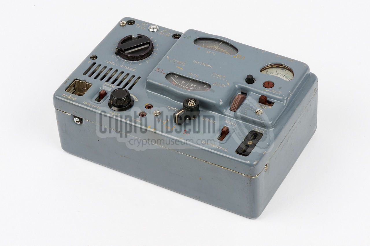
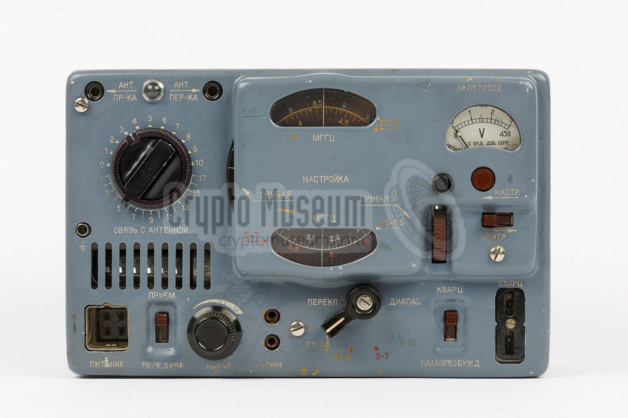
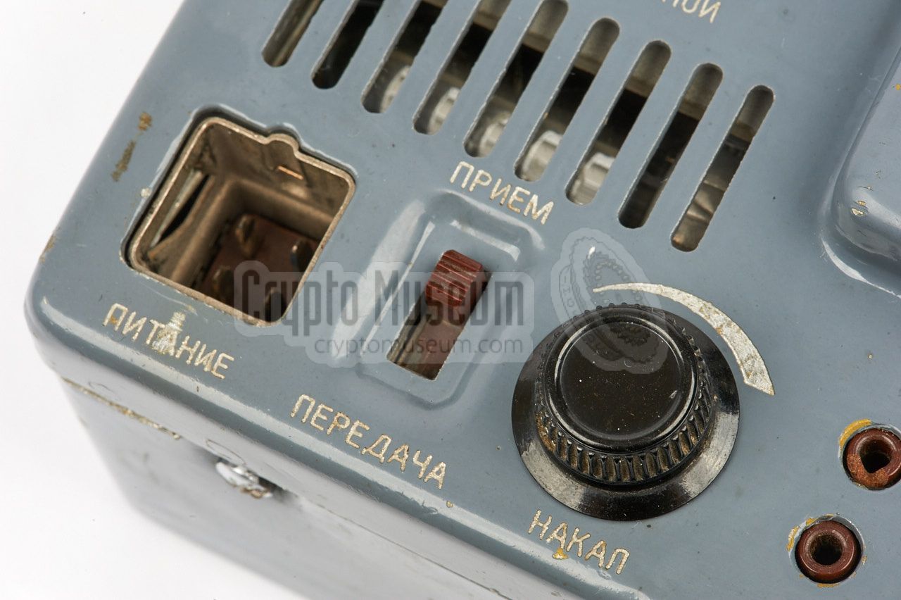
All controls and connections are located at the top surface of the
transmitter. At the bottom left is a 4-pin socket for connection of
the LT and HT voltages. Immediately to the right of this socket are
the ON/OFF switch, the adjustment knob for the filament voltage and
a socket for the morse key. At the centre of the control panel is
a large frequency scale that can be operated at its left. A fine tuning
knob is available at the bottom right of the scale. A 4-position
switch allows selection of the desired frequency band,
each of which has its own colour that corresponds with the scale.
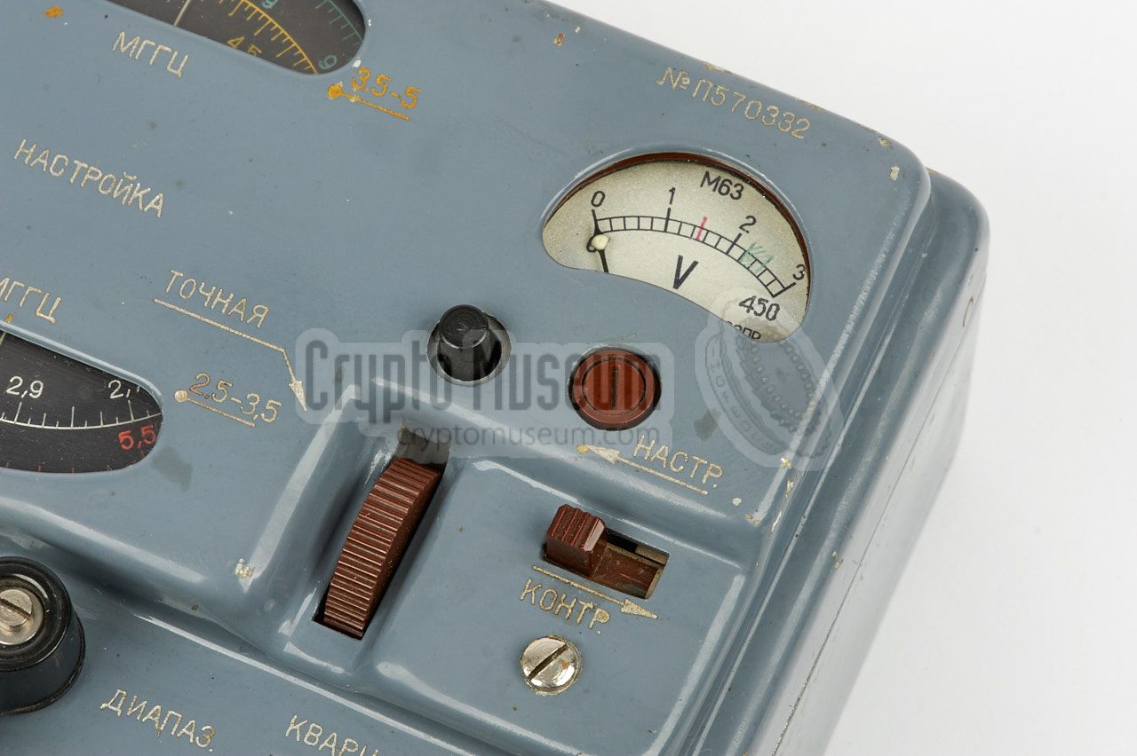
The meter at the top right can be used to check the filament voltage
(adjustable with the back known at the bottom edge), the HT voltage
(240V) or the anode current (which is an indication of the output power).
When transmitting, the large black double rotary knob at the top left
can be used to tune for maximum power, using the tuning lamp and the
current meter as indicators.
|
|
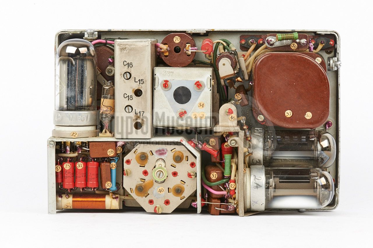
The interior of the P-57 transmitter can be accessed by loosening the
large screws at the sides, after which the case shell can be removed.
This reveals the interior as shown in the image below. All parts and
subassemblies are mounted to a subframe that is fitted to the radio's
front panel.
|
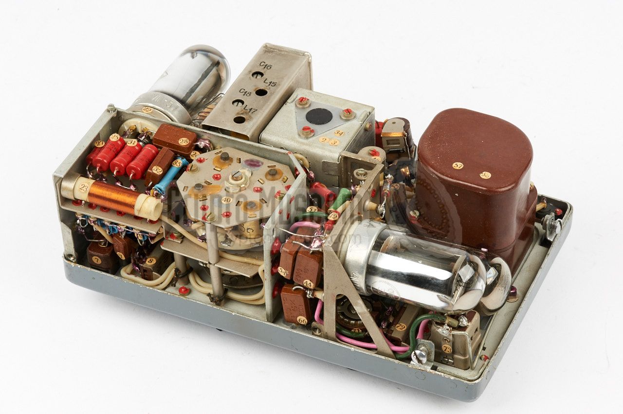
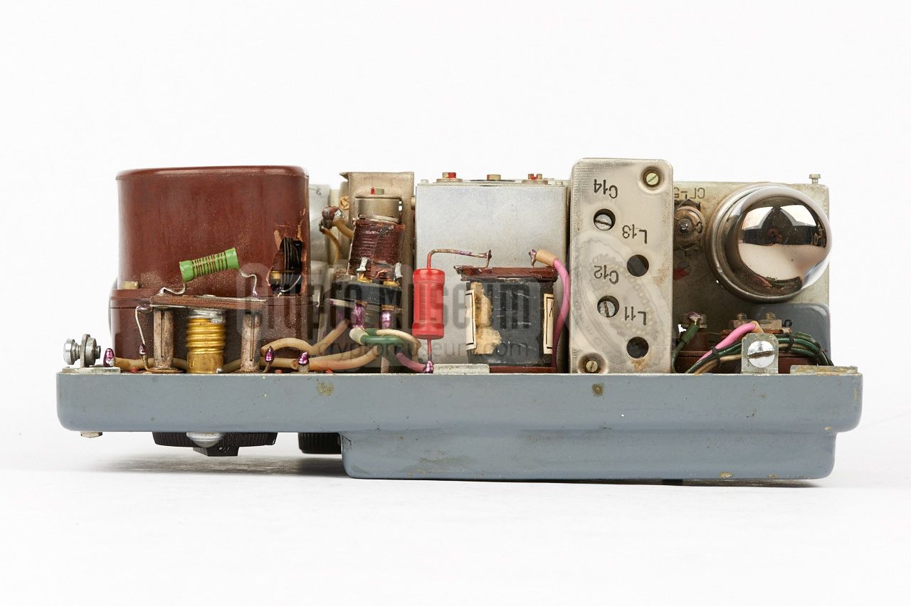
The image on the right shows the interior after the case shell has been
removed, seen from the top right. The circuit has three
identical Russian 4P1L (4П1Л) valves at its heart,
one of which is used as the oscillator.
The other two are used in parallel as the transmitter's Power Amplifier (PA).
The most complex part of the transmitter is the Variable Frequency Oscillator
(VFO) that is used when crystals are not available. It allows the transmission
frequency to be adjusted freely over each of its bands. The VFO and the
band selector are housed in a shielded enclosure.
|
|
|
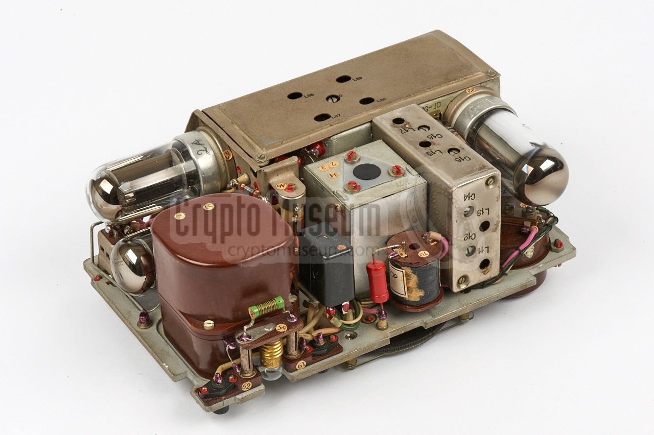
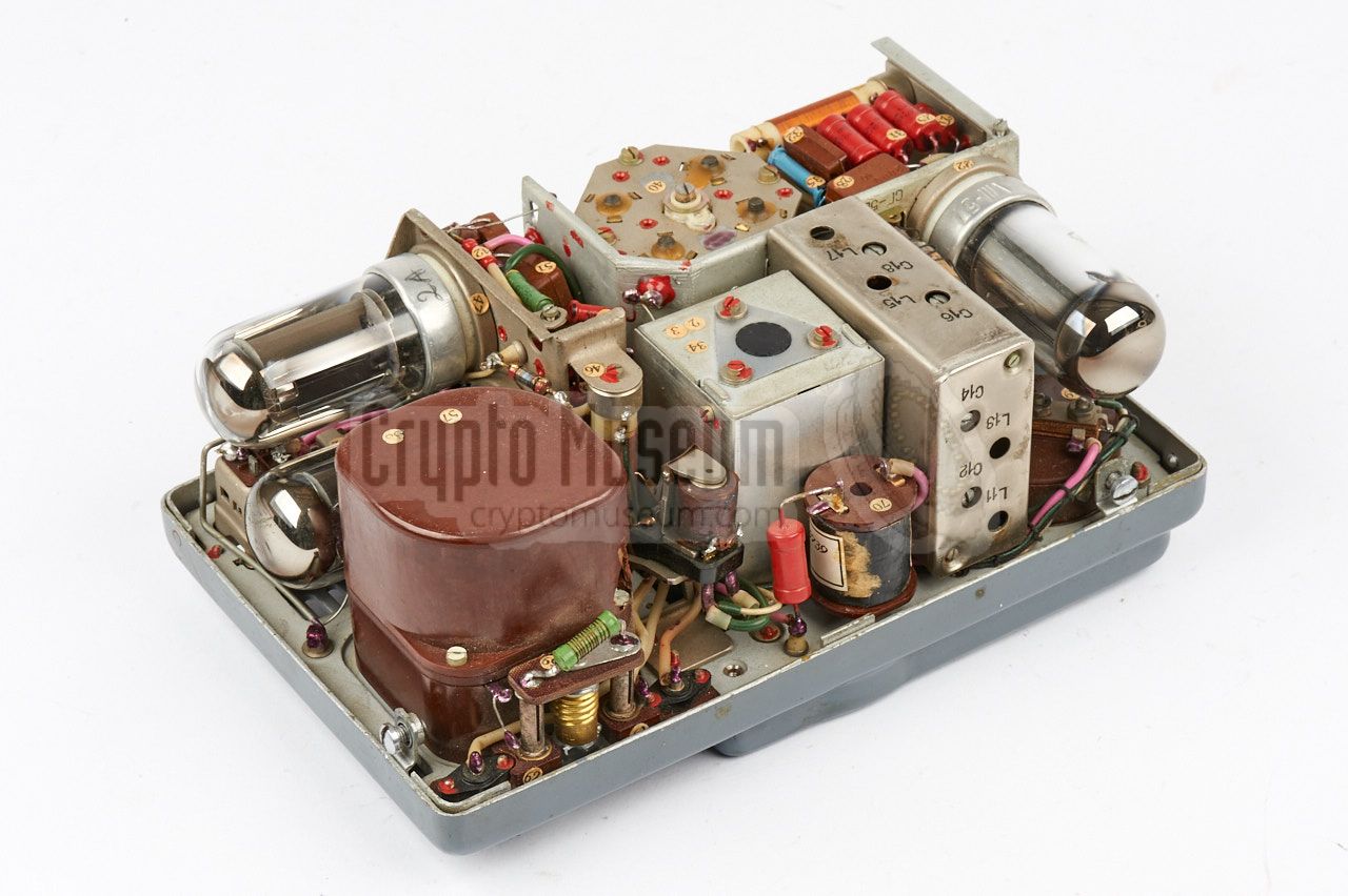
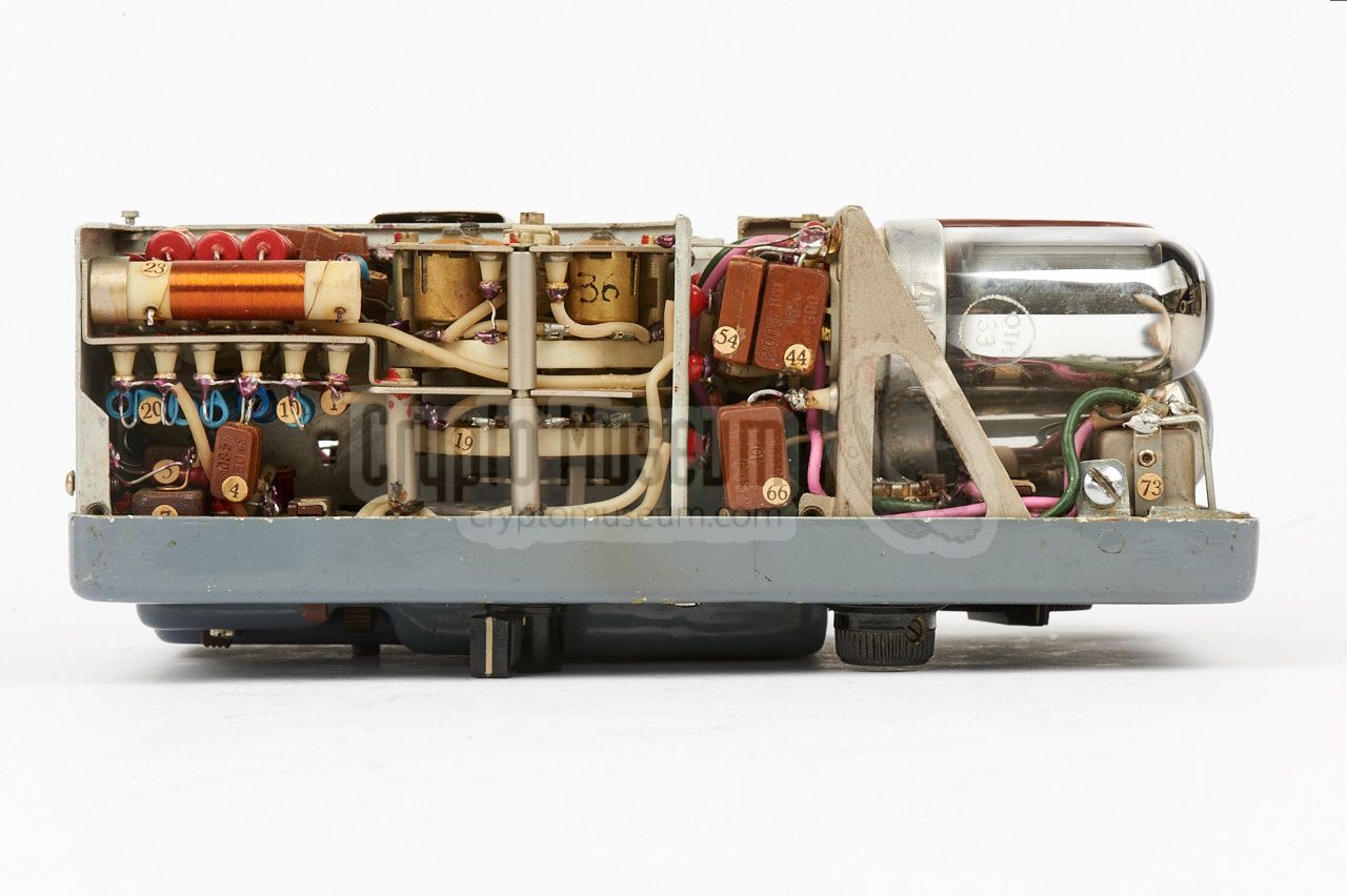
The image on the right shows the interior of the transmitter as seen from
the bottom left, after the protective VFO shield has been removed.
Note that even when a crystal is used to select the transmission
frequency, the band selector should be set to the required frequency range
and the tuning dial should be adjusted close to the actual frequency in order
to obtain the best result. This is necessary because it affects the tuned
circuit and, hence, the optimum coupling, between the oscillator and the
Power Amplifier.
|
|
|
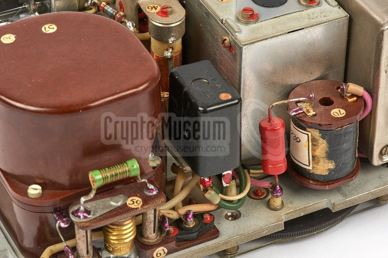
The brown oval block contains the antenna matching unit, which is in fact
a tuned circuit between the PA and the antenna, that consists of a multi-tap
inductor and an adjustable capacitor. This arrangement allows a wide variety of
antenna impedances to be matched. Note that the antenna matching unit has
to knobs: the outer ring, which selects a tap on the inductor, and the inner
part which adjusts the capacitor. When tuning, a small 2.5V/75mA glow lamp
is used as an indicator.
|
- 2.5 - 3.5 MHz (white)
- 3.5 - 5 MHz (yellow)
- 5 - 7 MHz (red)
- 7 - 10 MHz (green)
|
Frequency 2.5 - 10 MHz 1 - 4
Output 10 W Power LT: +2.1V, HT: +240V
|
-
Note that the frequency range of the receiver
is slightly wider: 2 - 12 MHz.
|
- LT (-4.5V)
- not connected
- LT (0V)
- HT (270V)
|
|
- scAvenger, Technical description of the RION spy set
Website with many photographs. Riga, Latvia.
21 January 2005. Retrieved October 2009. 1
- Louis Meulstee, Wireless for the Warrior, volume 4
ISBN 0952063-36-0, September 2004. 2
- Radio Scanner, Radio Station 'RION'
Website (Russian). Retrieved May 2016.
- KGB Bunker Museum, Lithuania
Personal correspondence, February 2017.
|
-
Website no longer available in 2016.
|
|
|
|
Any links shown in red are currently unavailable.
If you like the information on this website, why not make a donation?
© Crypto Museum. Created: Thursday 23 February 2017. Last changed: Thursday, 01 March 2018 - 08:01 CET.
|
 |

|
|
|


