|
|
|
|
|

|
|
Sweden Spy radio
The Ra-190 had two frequency bands (1.6 - 8 MHz) and (8 - 16 MHz) and produced
an output power of 0.8 and 0.4 Watt respectively, making it suitable for
short to mid-range CW (morse).
The transmitter is crystal operated whilst
the receiver features a Variable Frequency Oscillator (VFO).
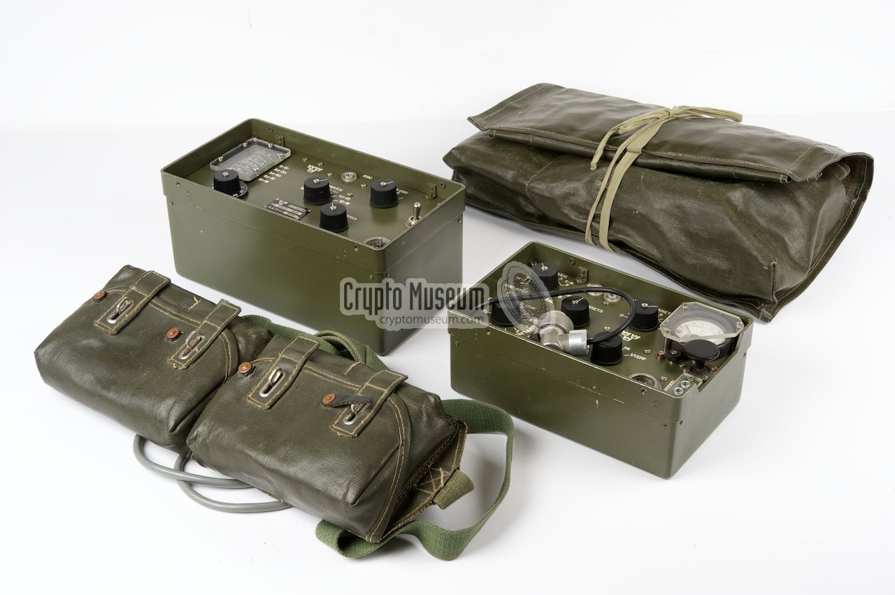
A complete Ra-190 station, with all accessories, weighs around 6.4 kg.
It was usually carried by a single person, but could also be shared by several
individuals. It was intended for stationary use (i.e. not portable),
as it requires a halve (½λ) wave-length or full wavelength
(λ) wire antenna.
|
|
|
The transmitter is suitable for CW (morse)
only and can be operated
by a built-in morse key, that is located at the right side of the control
panel, just below the meter. This key was for emergency purposes only
however, as a suitable external morse key was usually supplied with the set.
The receiver covers 1.1 - 16 MHz, divided over five ranges, with a gap
between 1.7 and 2.5 MHz. The Ra-190 was powered by two sets of dry batteries:
67.5 V (HT) and 3 V for the filaments of the valves (LT). The batteries were
housed in a wallet that could be carried under the clothing or uniform of
the operator, in order to keep them warm and dry when used
under harsh conditions.
|
|
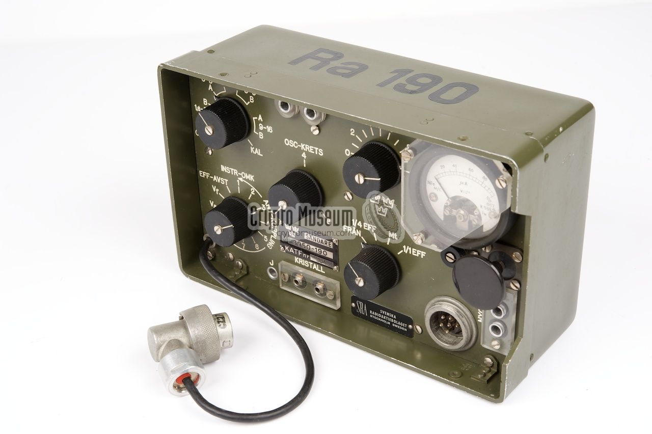
The crystal-operated transmitter is marked M-3950-190 and covers
1.6 - 16 MHz, divided over four frequency ranges (two bands):
The lower frequency band (1.6 - 8 MHz) uses the crystal in the fundamental mode
and produces an output power of 0.8 Watt. At the higher frequency band
(8 - 16 MHz) the crystal frequency is doubled and the output power is reduced to
0.4 Watt.
|
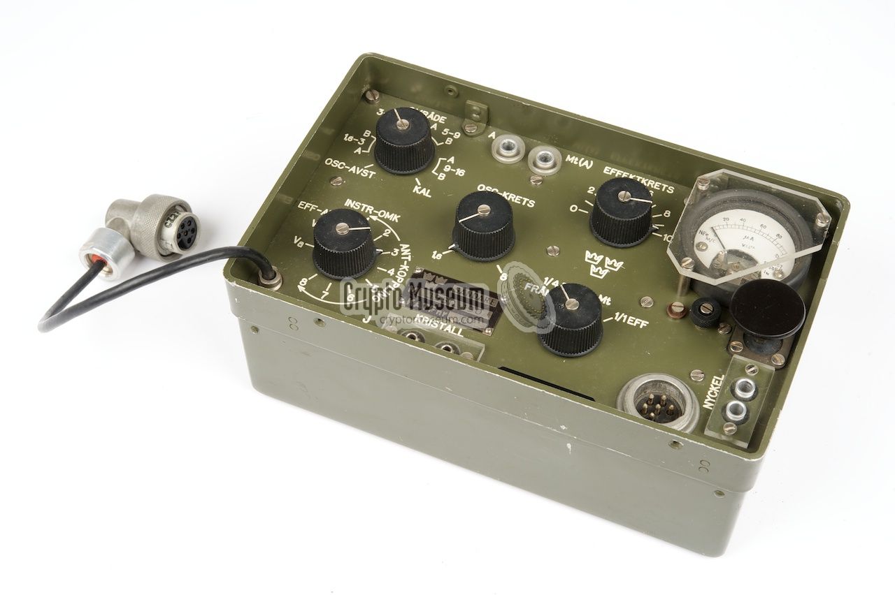
The transmitter is housed in a sturdy green metal case with a
well-structured recessed front panel. The antenna socket (A) is at the top,
with a switched loop output 'Mt(A)' for the receiver.
The valve-based transmitter is driven by a crystal that should be inserted
into the socket marked KRISTALL along the lower edge of the control panel.
The external battery pack should be connected to the 6-pin socket in the
lower right corner. It caries the 3V LT and 2 x 67.5V HT voltages. A fixed
'flying wire' with a 6-pin plug at the end is supplies power to the
receiver.
|
|
|
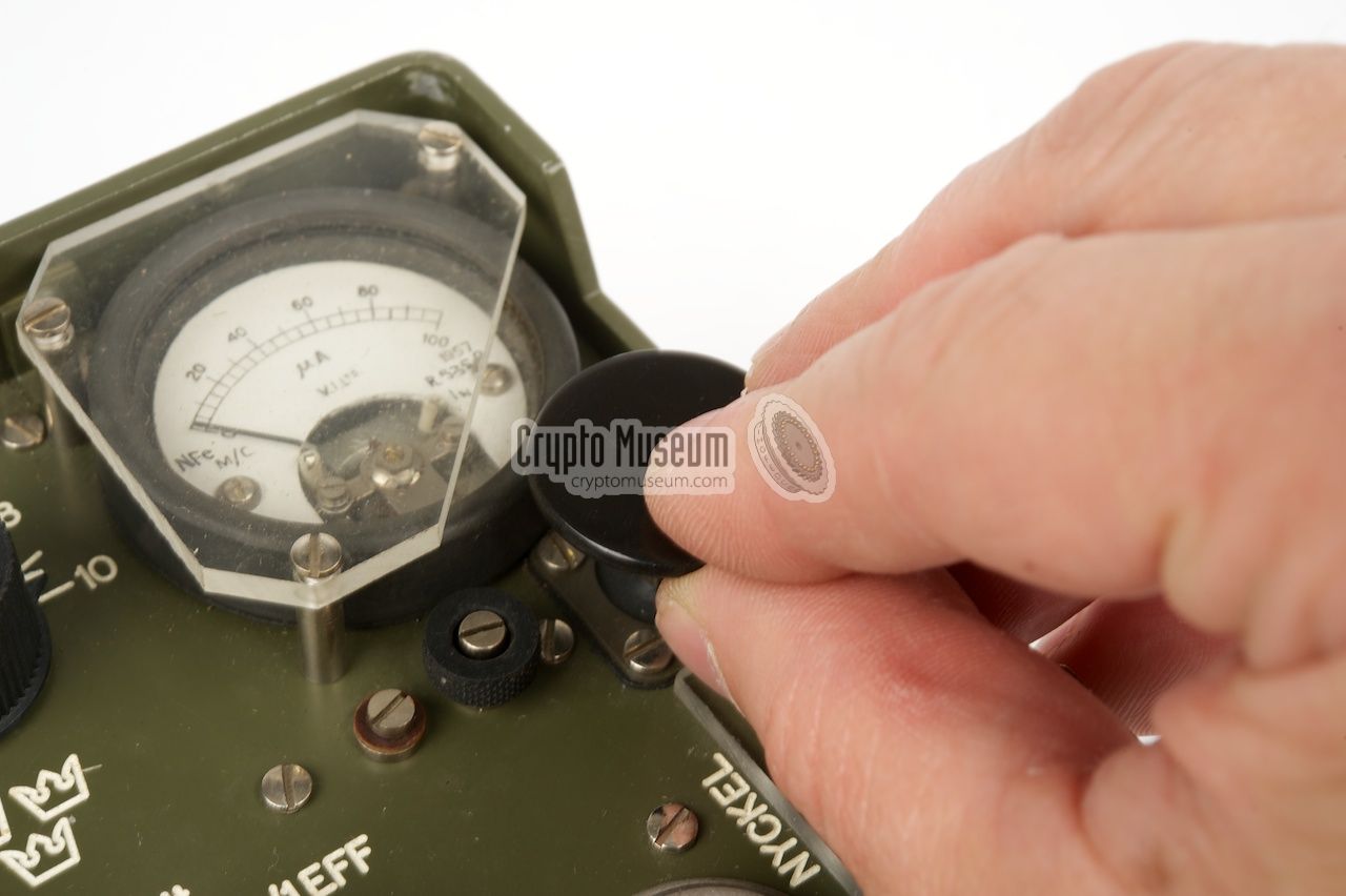
At the top right is a meter that allows the antenna to be tuned for maximum
antenna current.
The transmitter has a built-in morse key that is located at the lower right
corner of the meter. For this reason one of the corners of the protective
plexiglass over the meter has been cut off.
The transmitter is suitable for A1 modulation only (morse, CW).
The output power depends on the selected frequency range
and is either 0.4 or 0.8 Watt. When the conditions are sufficiently good, the
output can further be reduced to about ¼ of the nominal power. This
minimises the risk of detection and is extremely useful for Special Forces
operating behind enemy lines.
A 4-position rotary switch at the right half is used for selecting
the required mode of operation (MODE). In the leftmost position (FRÅN),
the radio station is switched off. In the rightmost position (1/1 EFF)
the transmitter is operated at maximum power. In the (1/4 EFF) setting,
the output power is reduced to about 25% and in the (Mt) setting,
the receiver is enabled (Mottagare).
|
|
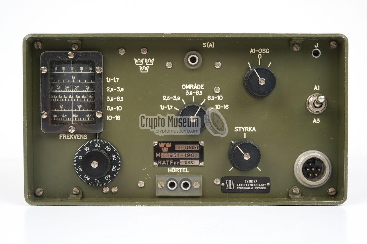
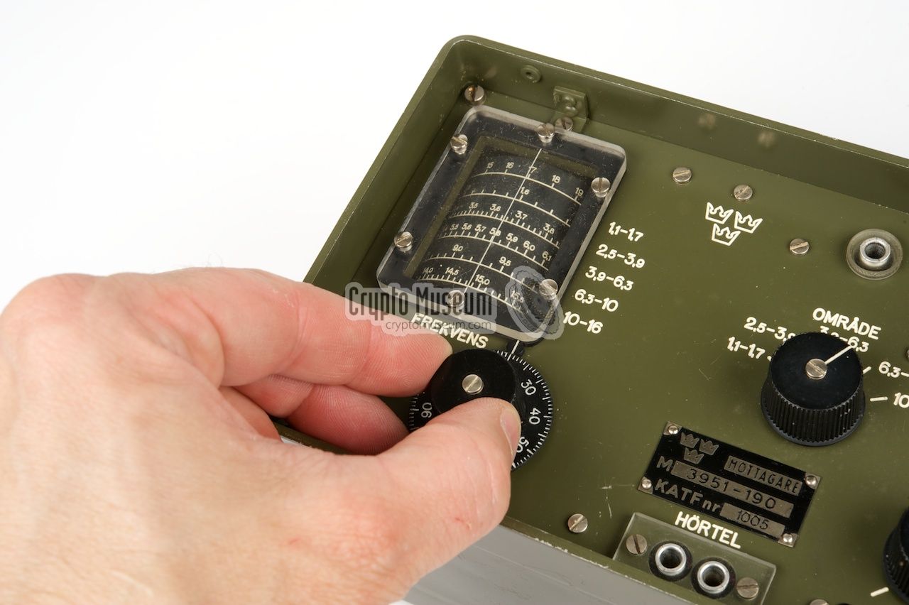
The receiver is slightly larger than the transmitter and is housed in a
similar case, with a recessed control panel.
It has a built-in Variable Frequency Oscillator (VFO) and can
be tuned freely from 1.1 to 16 MHz, divided over five frequency ranges,
with a gap between 1.7 and 2.5 MHz.
|
The rather sophisticated receiver is built around 8 valves (tubes) and
consists of an RF stage, mixer, oscillator, 2nd IF, detector,
BFO and AF output stage. The latter is suitable for the connection of
a pair of 600 Ohm headphones.
The receiver has a sensitivity of 15 µV at a S/N ratio of 7 dB.
The 2nd IF frequency is at 470 kHz. A toggle switch at the right hand side
is used to select the desired modulation type A1 (CW) or A3 (AM). In A1
mode, the Beat Frequency Oscillator (BFO) at the top right is enabled.
By default, it should be set to the 0-position.
|
|
|
The receiver is powered by the transmitter, which in turn is powered
by the battery pack. When in operation, the 3V filament power is always
supplied, so that the receiver is ready for use. The HT voltage is
controlled by the MODE selector on the transmitter.
Set it to (Mt) for reception.
If no transmitter is required, the battery pack can also be used to
power the receiver directly. In that case, the two 67.5 V HT batteries
are connected in parallel, so that they will last longer.
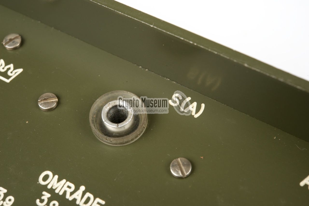
The antenna signal is also supplied by the transmitter by connecting
a short loop cable between Mt(A) on the transmitter and S(A) on the
receiver. The antenna signal is controlled by the MODE selector
on the transmitter. When in operation, the ground terminal (J) should
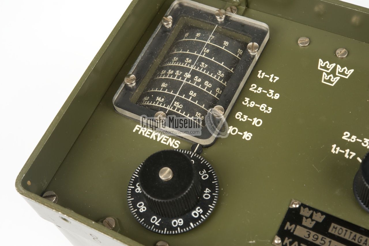
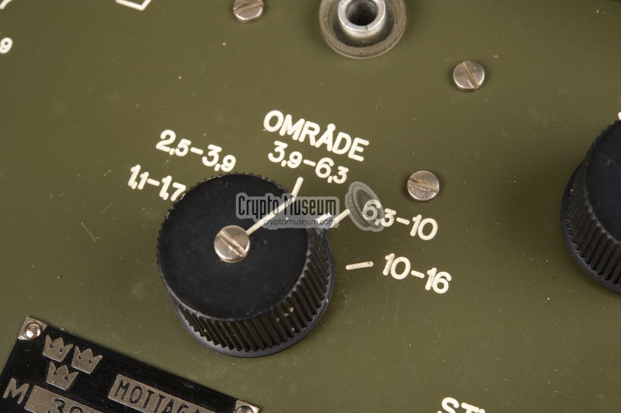
be connected to ground or to a suitable counterpoise. The knob at the
centre is used for selecting the required frequency range, each of
which corresponds to a horizontal line on the tuning scale (top left).
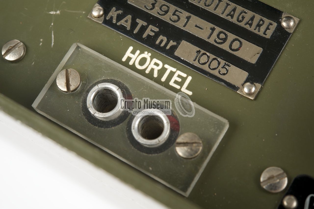
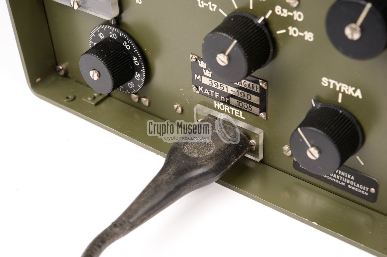
The 600 Ohm headphones, that comes with the Ra-190, should be connected
to the socket marked 'HÖRTEL' at the bottom edge of the control panel.
The volume level can be adjust with the potentiometer marked 'STRYKA'
to the right of the socket.
|
|
As the Ra-190 was intended for field use, it was supplied with it own
battery pack that supplies the two voltages (LT and HT) that are needed
to operate the radio station. To allow the station to be used under harsh
conditions, such as extreme cold, the battery pack came in the shape of
a belt-pack that could be worn by the operator under his clothing,
close to his body.
|
This was done to keep the battery dry and warm, so that it would last longer.
Dry 1.5 V batteries were used to power the filaments of the valves. When
bringing an old Ra-190 back to life, these batteries can easily be replaced
by four standard 1.5 V D-cell batteries (see the diagram below).
For the HT voltage, the radio requires 67.5 V DC with a relatively low current.
A suitable HT battery can easily be created by connecting 7
standard 9V block batteries in series (63 V). In order to be able to supply
the required voltage, two such packs are used in series/parallel.
|
|
|
The belt-pack supplied with the R-190 is made of green water-resistant
cloth and has two large pockets; one for the LT battery and one for the
HT battery. Inside each pocket are two smaller pockets in which the
individual batteries are stored. The belt-pack can be carried around
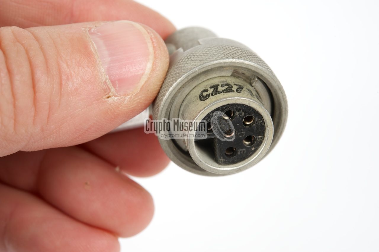
the waist by means of a green canvas strap. A short 6-wire cable, with a
rather strange 6-pin plug at the end, connects the battery to the transmitter. The receiver is powered from the transmitter.
|
|
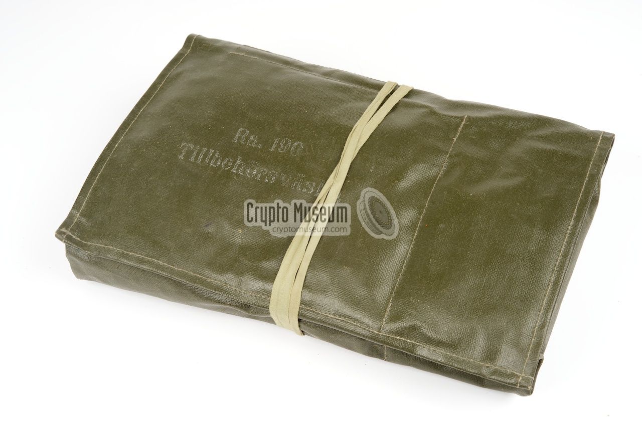
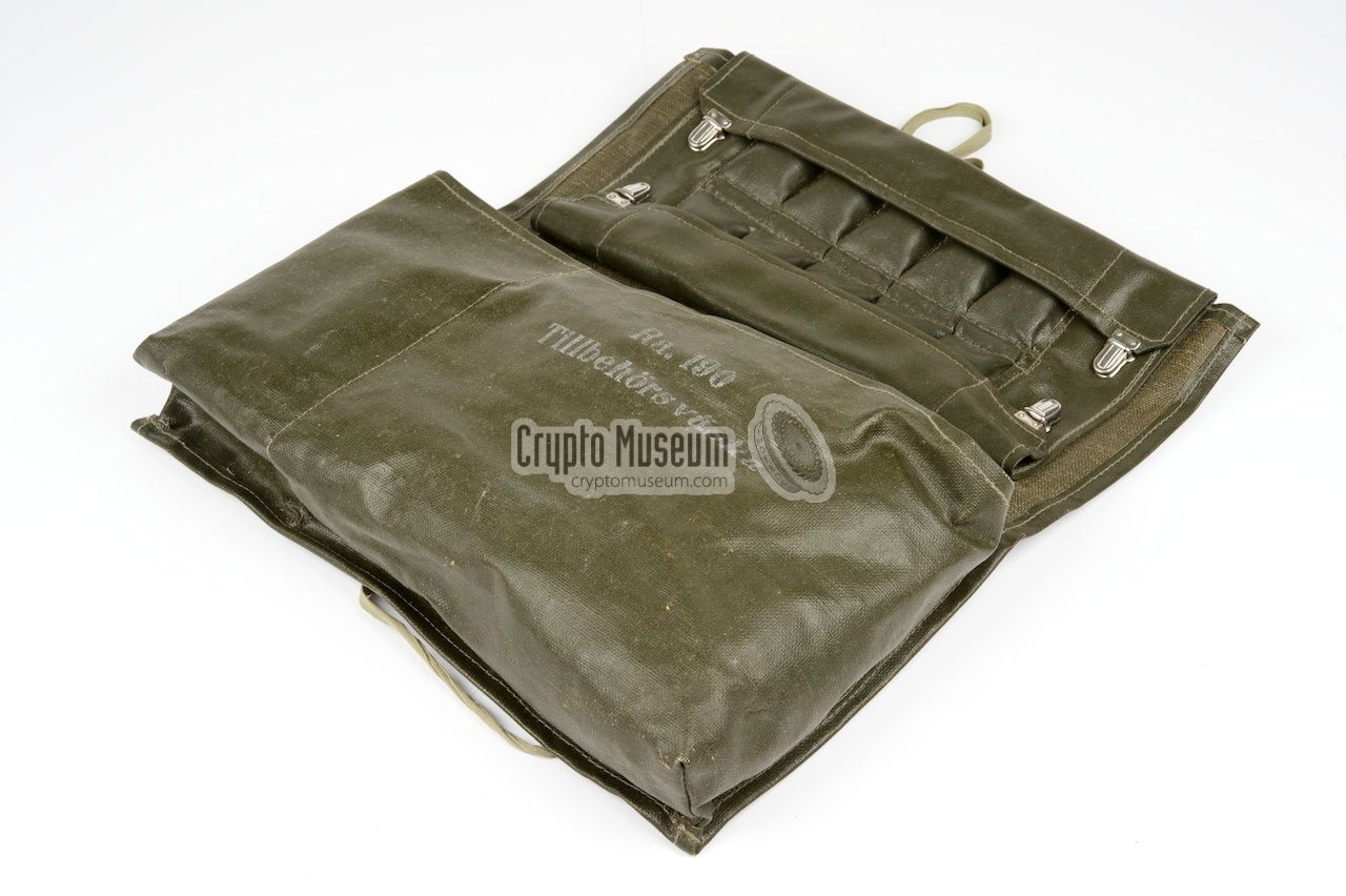
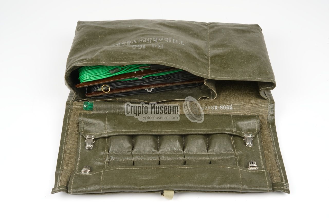
The accessories of the Ra-190 were stored in a large green wallet
that was supplied with the set. The wallet has two large compartments
in which the headphones, an external key, the antenna wires and some
spare valves were stored. The lid of the wallet has 10 small pockets
in which the crystals are stored. The batteries are housed in a
separate wallet that can be carried on the body.
|
The accessories and spare parts were usually stored in a large wallet
that was made of green water-resistant cloth. Inside the wallet are two
large pockets of which the smaller one is used for storing the spare
valves and some tools.
The larger pocket is use for storing the accessories, such as the
antenna wires, a throwing weight, the headphone and an external morse key.
These accessories are further listed below.
Inside the flap of the wallet are 10 small pockets that are used
to store the crystals.
|
|
|
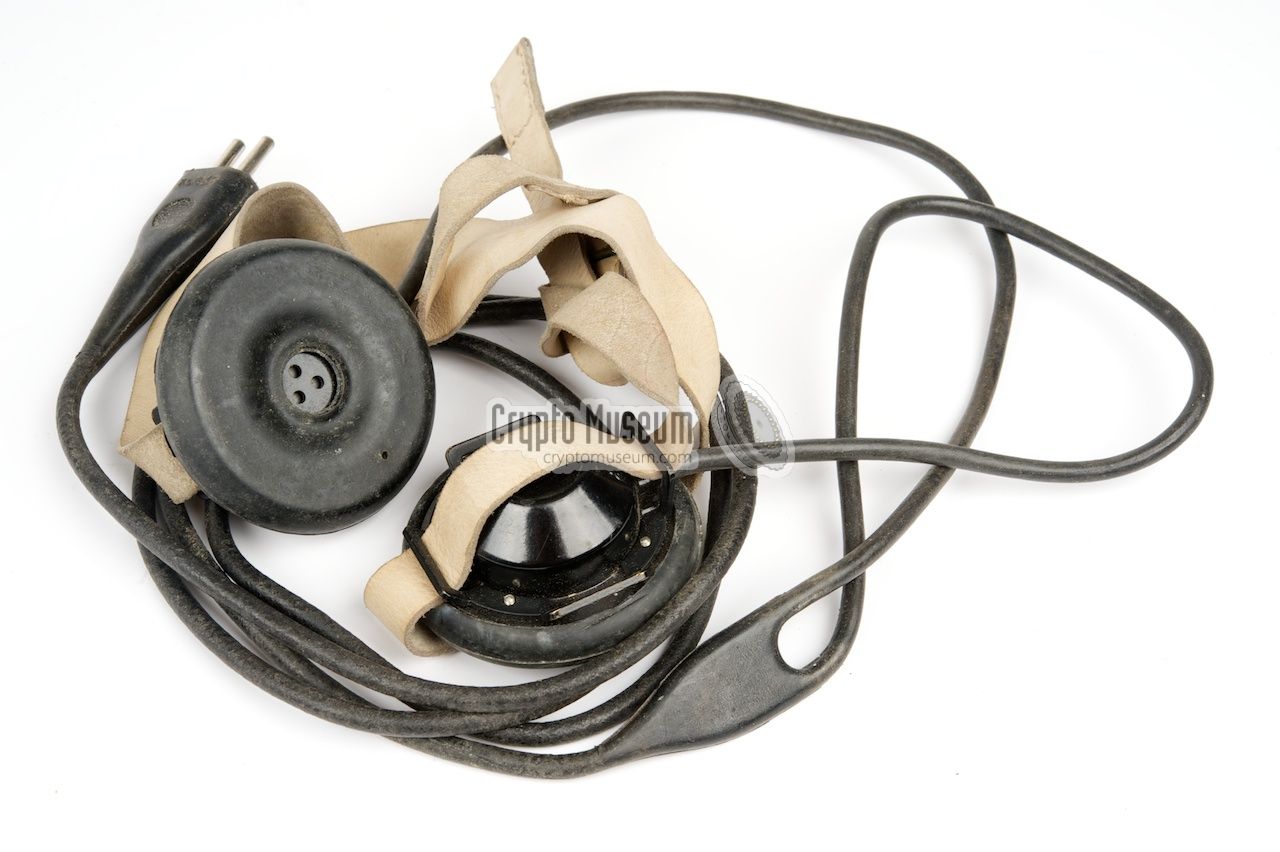
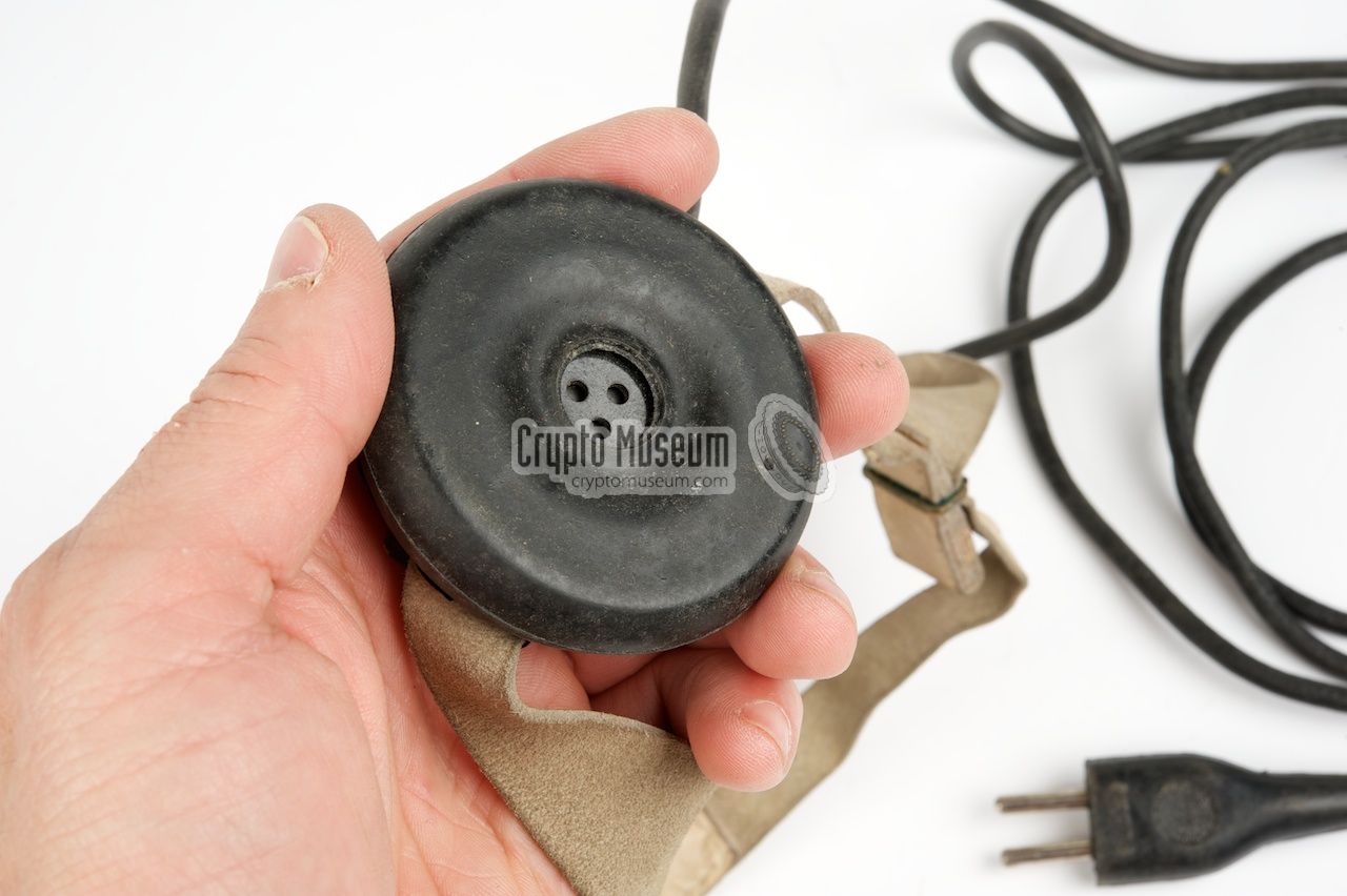
The audio output level of the receiver is just strong enough to drive a pair of
headphones, such as the ones shown in the image on the right. These headphones
were issued with the Ra-190 and should be connected to the HÖRTEL socket
at the bottom center of the control panel.
The headset has a rubber cable with a moulded 2-pin plug at the end.
|
|
|
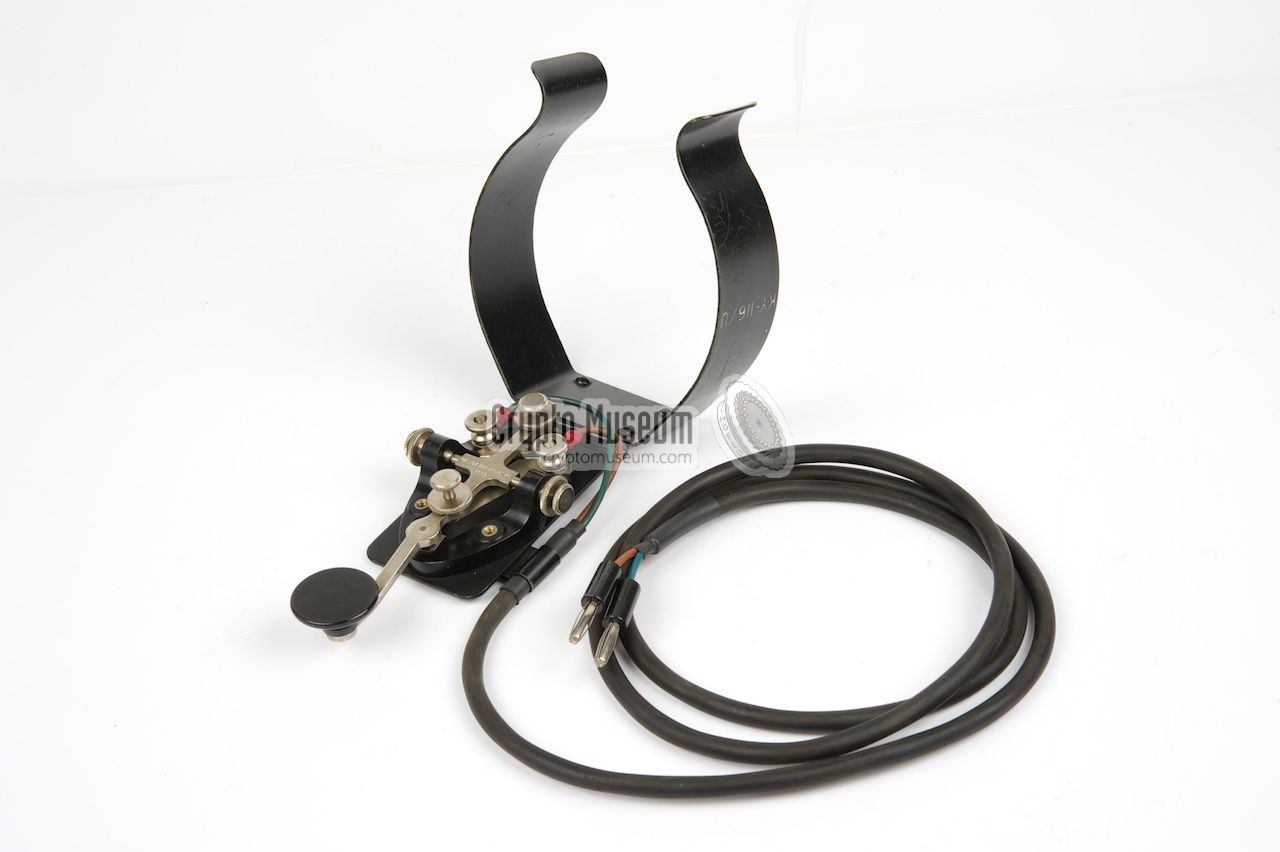
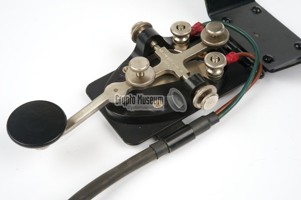
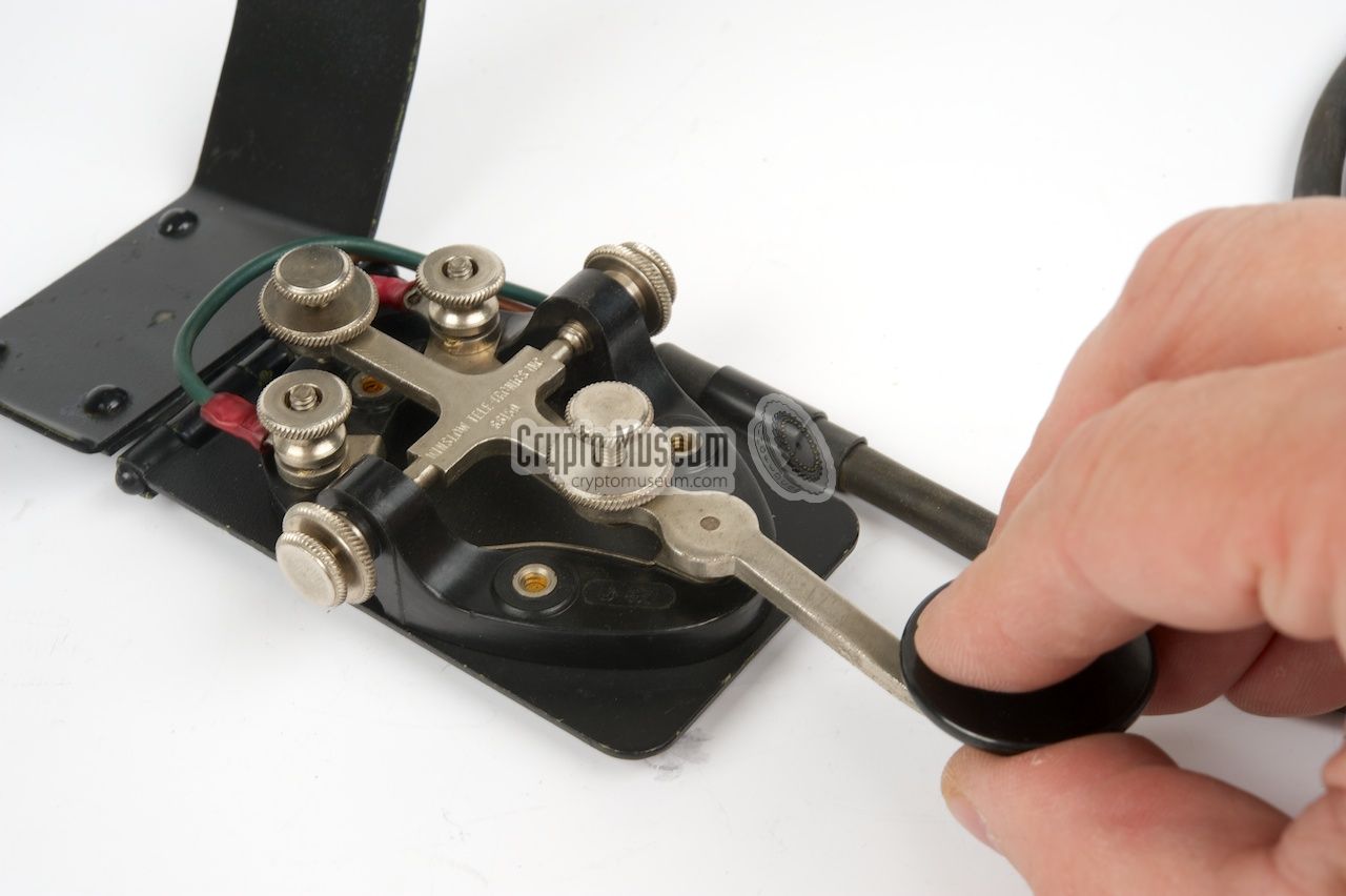
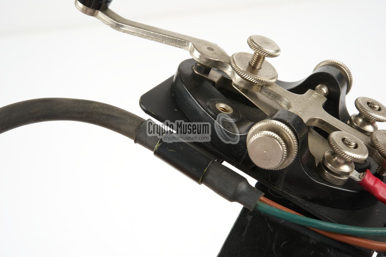
The station was supplied with an external morse key that could be mounted
to the operator's leg. It was connected to the NYCKEL socket at the
bottom right of the transmitter's control panel.
If the external key is missing, or when the operator has insufficient space,
the built-in morse key can be used as an alternative. It is located
just above the NYCKEL socket and has a large black knob.
In order to accomodate this key,
one corner of the protective plexiglass shield over the meter has been cut-off.
|
|
|
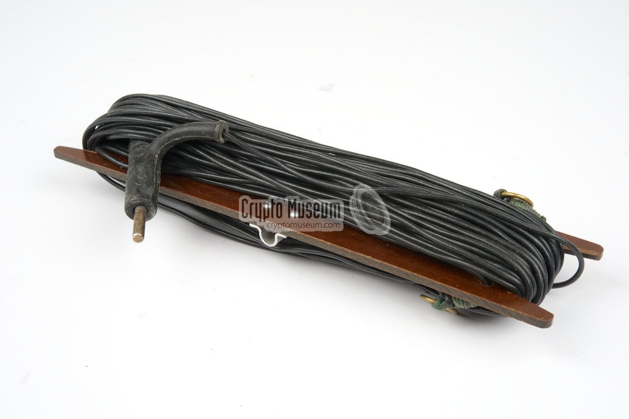
The Ra-190 is supplied with two wires that can both be used as antennas.
The longer one is green and is intended as a half-wave antenna for the
lower frequencies or a full-wave antenna for the higher frequencies.
When not in use, this wire can also be used for counterpoinse (ground).
|
|
|
The black wire is the shorter of the two. It can be used as half-wave
antenna for frequencies around 8 MHz and full-wave antenna for frequencies
between 14 and 16 MHz. When not in use, this wire can also be used as
counterpoise (ground).
The table on page 11 of the manual [3] shows which cable is best used
for each of the available frequency ranges.
|
|
|
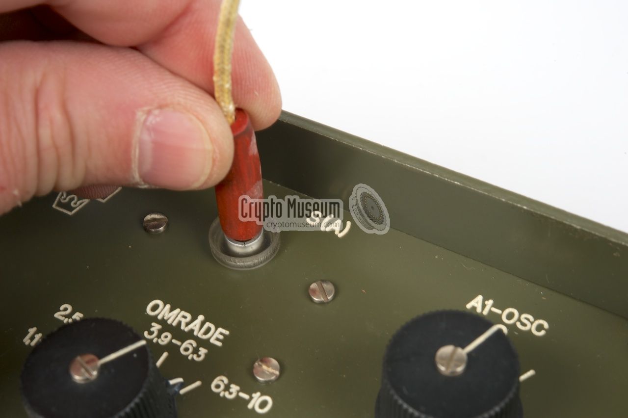
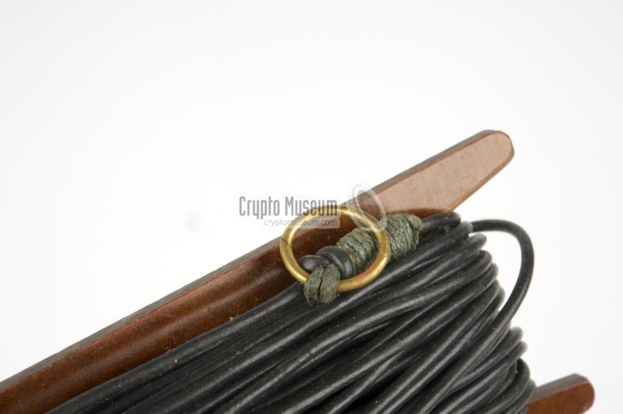
When fixing an antenna, e.g. between two trees, it might be useful
to attach one end to an (isolated) rope, so that it can be hanged
freely in the air, away from obstacles.
A red rope on a spool is supplied with the Ra-190. The spool has a
grip for easier unwinding.
|
|
|
When using the Ra-190 in the field or in a forest, which was usually the case,
the antenna often had to be improvised. In most cases, a nearby tree
would be used as a supporing mast for the ½λ or λ wire
antenna.
As the antenna wire should be mounted as high as possible,
the throwing weight, shown in the image on the right, was supplied.
It is attached to one end of the wire and and then thrown over a branch
of the supporting tree.
|
|
|
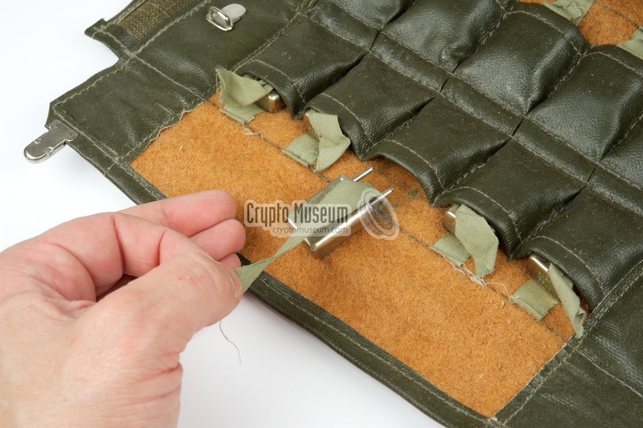
In total, 10 valves are used in the Ra-190: 2 in the transmitter
and 8 in the receiver. As only five different types of valves are used,
one of each type is supplied as a spare. They are stored
inside the smaller pocket of the accessory wallet.
For an overview of the used valves, please refer to the
technical specifications below.
|
|
|
A short loop wire, with a banana-type plug at either end, is needed to
distribute the antenna signal from the transmitter to the receiver.
It should be connected between the transmitter loop output marked 'Mt(A)'
and the antenna input marked 'A' of the receiver.
|
|
|
|
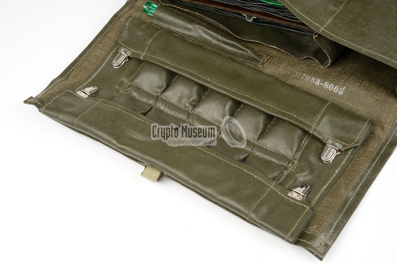
A small flat screwdriver was supplied with the Ra-190.
It was kept in a small pocket inside the flap of the accessory wallet
and was suitable for opening the cases of the transmitter and the
receiver, when servicing the units or replacing the valves.
|
|
|
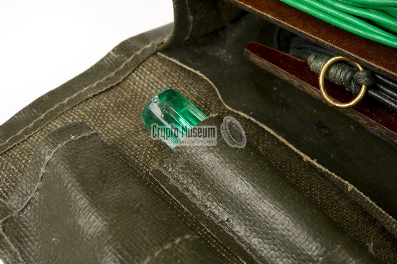
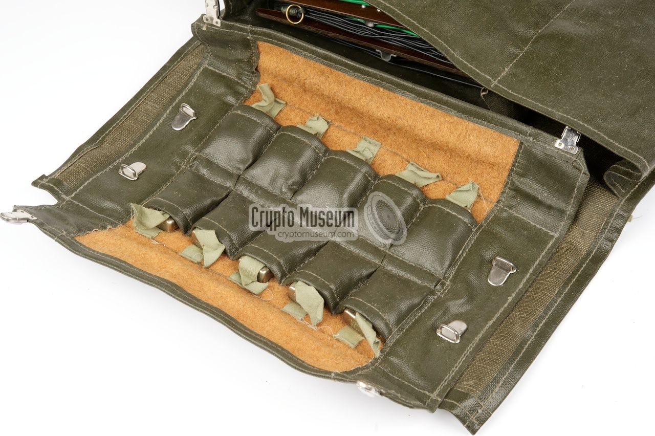
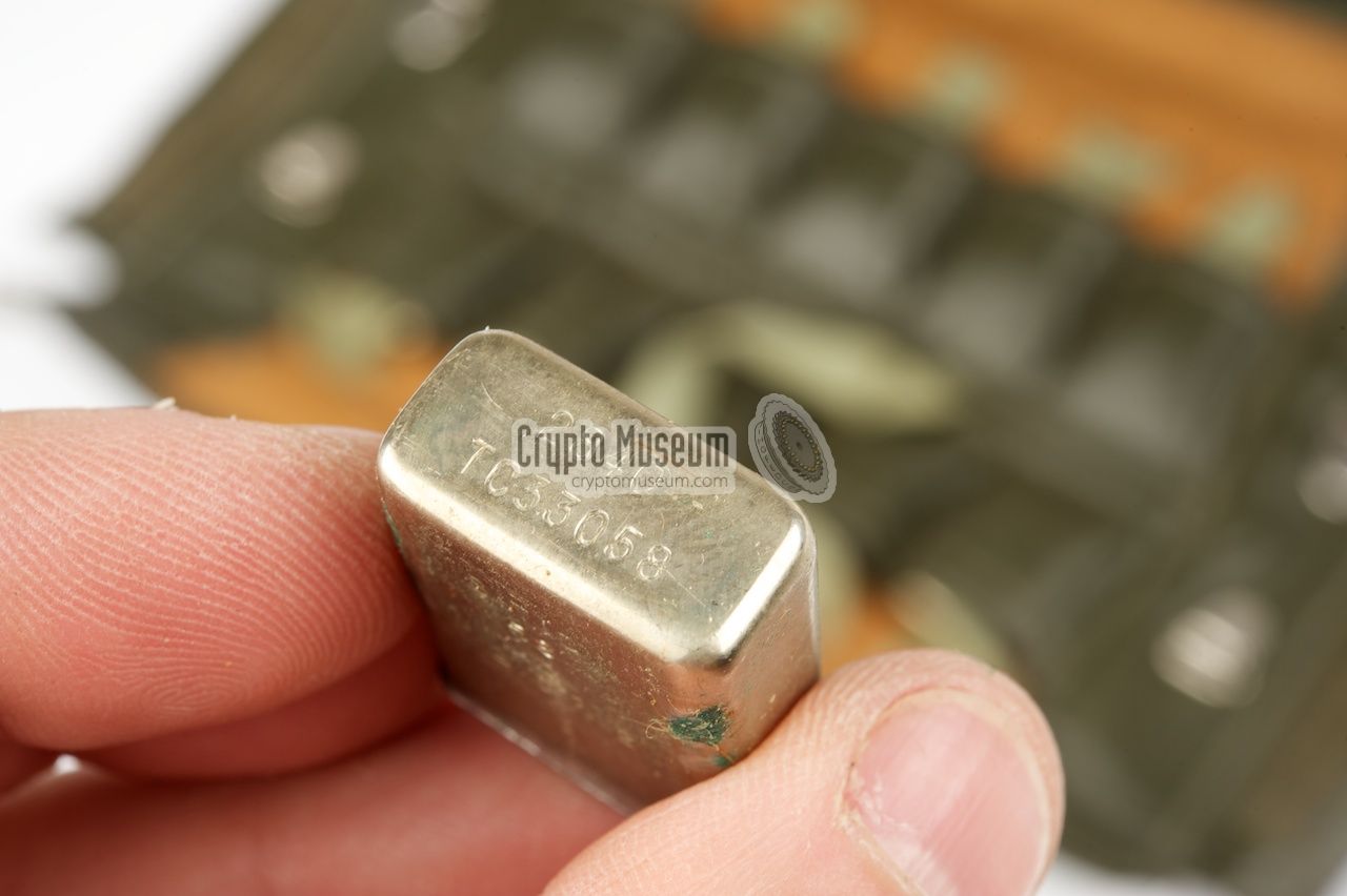
As the transmitter of the Ra-190 is crystal operated, as set of 10
different crystals was supplied with the radio station. Each crystal
was stored in a small padded pocket inside the flap of the accessory wallet.
A full overview of the available crystals is given below [5].
A crystal can be removed from its pocket by pulling a green ribbon that
is folded around the crystal. After use, the crystal should be restored
in its pocket by pushing the crystal (and the ribbon) back in place, with
the contact pins first.
|
|
|
| Order # | Code | f0 (kHz) | TX < 8 MHz | TX > 8 MHz |
|
|
| F1080-033057 | Tc 33057 | 2555 | 2.555 | - |
| F1080-033058 | Tc 33058 | 2840 | 2.840 | - |
| F1080-033059 | Tc 33059 | 3395 | 3.395 | - |
| F1080-033060 | Tc 33060 | 3755 | 3.755 | - |
| F1080-033061 | Tc 33061 | 4385 | 4.385 | 8.770 |
| F1080-033062 | Tc 33062 | 4880 | 4.880 | 9.760 |
| F1080-033063 | Tc 33063 | 5060 | 5.060 | 10.120 |
| F1080-033064 | Tc 33064 | 6005 | 6.005 | 12.010 |
| F1080-033065 | Tc 33065 | 7325 | 7.325 | 14.650 |
| F1080-033066 | Tc 33066 | 7955 | 7.955 | 15.910 |
|
|
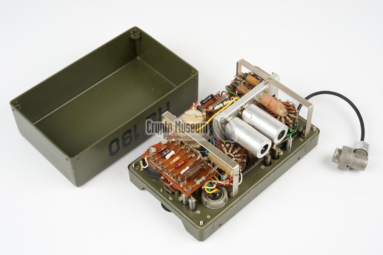
The interior of both the transmitter and the receiver can easily be accessed
by loosening the four bolts in the corners of the control panel of each unit.
This allows the front panel, to which all electronic components are mounted,
to be extracted from the case, which is very service-friendly.
|
The design of the transmitter is pretty simple and consists of no more than
two identical 3A4 valves. As it is only suitable for CW (morse), there is no modulator. The first 3A4 valve acts as the oscillator which runs up from
0 to 8 MHz.
The second stage has a double function. When the transmitter is used at
frequencies up to 8 MHz, it acts as a straight power amplifier (PA), and
produces approx. 0.8 W. At frequencies above 8 MHz however, it acts as
a frequency doubler as well. As a result, the output power is reduced by half
at this range, to about 0.4 W.
|
|
|
The output can further be reduced to about 1/4 of the nominal power, by
setting the the MODE-selector to 1/4 EFF. The image above shows the interior
of the transmitter, which is rather clean. The valves are protected by
aluminium cans and can easily be swapped in case of a failure.
|
As usual, the design of the receiver is much more complicated, which is why
the case of the receiver is slightly larger than that of the transmitter.
It is a single superheterodyne design with an Intermediate Frequency (IF) of
470 kHz, and contains no less than 8 valves
The design of the interior is very compact, with all passive components
located in a couple of metal enclosures at the centre. All valves and the
adjustable coils are mounted to the side of these enclosures, so that they
can easily be accessed when the device needs calibration or repair.
|
|
|
The block diagram below show how the receiver is constructed.
At the left is the HF pre-amplifier built around an 1L4 valve.
It is followed by a mixer (1R5) that combines the HF input with the signal
from the oscillator (3V4), resulting in an 470 MHz IF signal.
The IF signal is amplified twice (2 x 1L4) before it is fed to the
detector (1U5) which is also used as the LF pre-amplifier.
The LF-signal if finally amplified to headphones level by the
LF output amplifier (1L4). For the reception of CW signals,
a Beat Frequency Oscillator (BFO) built around a 1L4 is present.
It is activated by setting the Modulation switch to A1
and can be tuned with the A1-OSC knob.
|
|
|
About Svenska Radioaktiebolaget (SRA)
|
|
|
The manufacturer of the Ra-190, Svenska Radioaktiebolaget (SRA), was founded
in Stockholm (Sweden)
in 1919 by five Swedish companies who had developed an interest in the (then)
new radio technology. Amoung these companies were AGA, ASEA and
LM Ericsson.
In the first years of its existence, the company faced serious problems with
the development and manufacturing of radio equipment,
due to patent protection by large international corporations.
All that changed when, in 1921, SRA was restructured after Marconi had acquired
43% of its shares, allowing the company to use proprietary technology from
Marconi. During the early 1920s, SRA developed equipment for wireless
telegraphy and broadcasting. The first domestic radio was released in 1922.
Like most other brands in those days, it required headphones in order to
listen to a broadcast. Later improved models were
sold under the Radiola brand [1].
In autumn 1927, LM Ericsson
became the major shareholder (57%) when it took
over the shares from the four Swedish partners, whilst Marconi remained a
minority shareholder with just 43%. The first Radiola radios with built-in
speakers were introduced in 1928, eventually followed by the first portable
radio (1939), the first gramophone (pickup) and the first transistor
radio (1958).
In 1944, SRA started developing two-way radio systems, initially for
the police and other law enforcement agencies.
During the 1950s, SRA also developed two-way radio systems
for the Department of Defense (DoD), such as the Ra-190 special forces radio.
As these developments competed with former shareholder AGA,
the principle owner - LM Ericsson - decided to sell its Radiola brand to AGA
in 1964, allowing SRA to concentrate on the development of two-way radio.
During the 1970s and 1980s, SRA further developed itself as a specialist
company in the field of two-way radio, mainly by acquiring several other
companies. The first large company to be taken over by SRA in 1978 was
Sonab Communications, which itself was formed in 1974, by merging
Sonab and AGA's radio operations. These developments eventually led to
Ericsson
becoming a major player in mobile telecommunications. After acquiring
the remaining shares from Marconi, SRA was fully integrated with
LM Ericsson
and went on as Ericsson Radio Systems AB.
|
Device Spy radio set Purpose Clandestine radio contact Model Ra-190 Country Sweden Year ~1958 Bands 2 Frequency 1.6-8 MHz, 8-16 MHz Weight 6.4 kg (including battery belt)
|
Model M-3950-190 Range 1 1.6 - 3 MHz Range 2 3 - 5 MHz Range 3 5 - 9 MHz Range 4 9 - 16 MHz Valves 2 x 3A4 Output 0.8 W (1.6 - 8 MHz), or 0.4 W (8 - 16 MHz) Dimensions 11.5 x 18.5 x 7.5 cm Weight 1.2 kg
|
Model M-3951-190 Range 1 1.1 - 1.7 MHz Range 2 2.5 - 3.9 MHz Range 3 3.9 - 6.3 MHz Range 4 6.3 - 10 MHz Range 5 10 - 16 MHz Valves 5 x 1L4, 1 x 1R5, 1 x 1U5 and 1 x 3V4 Sensitivity 5 µV @ 7 dB S/N IF 470 kHz Headphones 600 Ohm Dimensions 11.5 x 21 x 10 cm Weight 1.8 kg
|
LT 3 V (filament) HT 2 x 67.5 V
|
- Wikipedia, Svenska Radioaktiebolaget
Swedish. Retrieved June 2014.
- Louis Meulstee, Wireless for the Warrior, volume 4
ISBN 0952063-36-0, September 2004
- Beskrivning av RADIOSTATION 190, Ra 190, Del I
Description of Radio Station 190 (Ra 190) Part 1 (Swedish).
Swedish Royal Army Admnistration. 1958. Retrieved June 2014. 1
- Kompendium över Radiostation Ra 190, M 3955-190, Del II
Technical Description of Radio Station Ra 190, Part 2 (Swedish).
Date unknown. Retrieved June 2014. 1
- Thomas Hörstedt (SM7DLF), Ra 190
Website Grön Radio. Retrieved June 2014.
|
|
|
|
Any links shown in red are currently unavailable.
If you like the information on this website, why not make a donation?
© Crypto Museum. Created: Thursday 12 June 2014. Last changed: Wednesday, 05 November 2025 - 12:10 CET.
|
 |

|
|
|
|