|
|
|
|
|

|
|
USSR Cold War R-353 → ← R-350M
The radio is fully self-contained and is powered by a
6V (wet) battery
that is stored inside the top lid. A short cable at the front panel
connects the radio to the battery, giving it approximately 15 minutes
of life.
Once the battery is exhausted, it can be recharged with the
hand-operated power generator that was also supplied with the set.
Alternatively, the radio can be powered by an external source,
such as the 6V battery of a car, or an external mains power supply unit (PSU).
Suitable cables for this were provided
in one of the pockets of the canvas manpack cover.
|
|
|
|
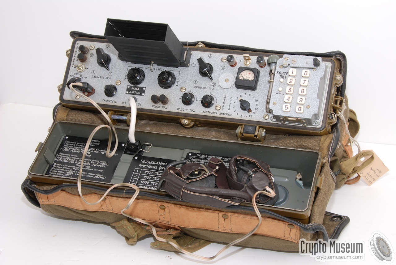
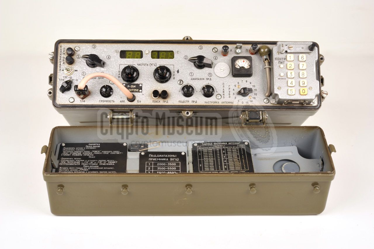
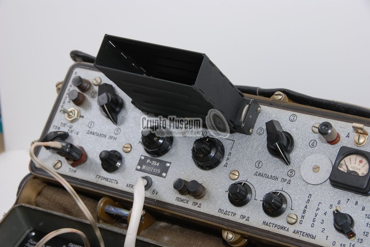
The receiver (left) and the transmitter (right) each have their own controls
and frequency display, allowing split-frequency operation.
A separate viewer
can be fitted to the front panel to improve the
readability of the projection scales.
The supplied headphones should be connected to the 2-pin socket
at the left of the front panel.
A light bulb on a flexible arm is present (right) to allow the
burst transmitter to be operated in the dark.
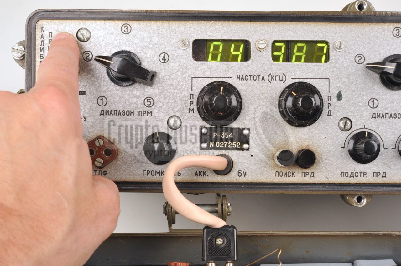
Both frequency displays are projection scales,
altough a later version of the R-354
(modified by Tesla
in Czechoslovakia)
had LED displays.
|
-
The Russian word Шмель (pronounced 'Schmel') means Bumblebee.
|
|
Apart from small manufacturing differences, the following versions are known:
|
- R-354
This is the standard version of the radio set. It was produced in the
Soviet Union (USSR),
probably at the Proton factory in Charkov (Ukraine). This version
has two projection scales for the RX and TX frequency readout respectively.
- R-354/CZ
This is essentially the same version as the one above, but upgraded with
a digital readout. In this version the projection scales have been replaced
with 7-segment displays and the black frame in front of the frequency windows
has been removed. The modified radio still bears the model number 'R-354',
but since the modification was done in Czechoslovakia, by
Tesla, we have added
the 'CZ' suffix, in order to discriminate it from the original one.
|
|
|
Standard version
R-354 Шмель
|
|
|
The diagram below shows the layout of the control panel of the standard
version of the R-354. The control panel is normally covered by the top lid
when the radio is in storage. After opening the top lid, the white power
cable (6V DC) should be connected to the battery
(which is mounted inside the top lid) or to an external 6V DC
power supply unit, or to the 6V battery 1 of a vehicle.
The radio can roughly be divided into four sections. At the left is the
receiver, which has its own tuning knob and frequency readout. AF output
is supplied to a pair of headhones and the volume is adjustable. To the right
of the receiver is the transmitter, which also has its own frequency adjustment
and readout. At the right is the antenna tuning section and the
burst transmitter. A small lamp allows the indicator to be read
when operating in the dark. The lamp is mounted on a spring and is turned ON
by releasing the spring from its storage position under the hook.
|
 |
-
When the R-354 was introduced in the mid-1960s, many cars still had a
6V battery.
|
|
|
Czech version
R-354/CZ Čmelák
|
|
|
In the mid-1970s, some of the R-354 units that had been supplied to
Czechoslovakia (CZ) were upgraded a with a digital readout,
which took the place of the existing projection scales.
The modification was carried out
at the Tesla factory
and consisted of a small unit,
roughly the size of a Eurocard PCB (10 x 16 cm),
and a 5-digit green 7-segment LED display.
The black window pane of the old projection scales was removed and replaced
by clear plastic windows as shown here:
In order to reduce power consumption — the battery of the R-354 didn't
not last very long — the LED display is only turned on when one of the
calibration buttons at the top left is pressed. This also has the advantage
that it does not reveal the position of station operated in the field.
After the modification, the name of the unit (on the name plate at the front)
was not changed. The only way to tell the difference with the original version,
is by looking at the frequency readout. The name R-354/CZ is suggested by
us in order to identify the modified Czech version.
➤ Look inside the Czech version
|
|
|
Sending messages in morse code
|
|
|
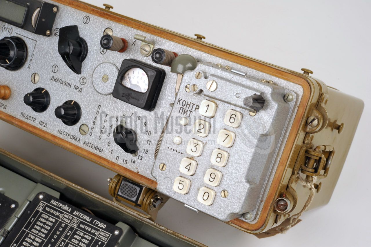
Built-in burst keyer
Like its predecessors,
the R-354 can only send messages in
morse code, using the integrated
morse burst encoder at the front right of the radio.
The morse unit, that can be recognised by the
numerical key pad (0-9) and the manual morse key,
is bolted onto the front panel of the radio.
|
There are three ways for sending messages in
morse code.
(1)
The first method is by using the small black morse key just above the key pad. Messages can be sent directly,
but this was only used in case of an emergency. Furthermore, the key is not very
comfortable, making it rather difficult to send morse messages faultlessly.
(2)
If the operator was not trained in giving morse, he could use the number keys to
send a pre-coded (numerical) message, simply by typing the appropriate numbers.
In case of a mistake, the user would press the ······ button.
|
|
|
(3)
The normal mode of operation however, was by using the built-in morse burst
transmitter which allowed pre-coded numerical messages to be sent
at very high speed, minimising the risk of interception and
radio direction finding.
For this, the messages were first stored on photo film
as a series of punched holes, much like with the R-350 radio
set. Standard 35 mm photographic film was used for this purpose,
as it was readily available in most countries around the world.
Agents in the field could buy 35 mm film
in virtually any store without attracting any attention.
Unlike the R-350 however, the R-354 consumes only half the amount of film,
as the film was first sliced in two halves (of 17.5 mm each) using a supplied
film cutter.
Once sliced, the film was fed through a puncher,
which punched a pattern of
holes in the film, each representing a number (0-9).
Two different versions of the film puncher have been identified:
a large one
and a small one.
|
|
Below are some audio samples of the R-350M, recorded by collector
Karsten Hansky in Germany in June 2014 [2].
The radio was connected to a dummy load and an
ELAD FDM-S1 was used to receive and record the signal. Further sound
processing was done with Audacity (software).
|
In this video, German collector karsten Hansky shows how a perforated
half 35 mm film is used to automatically send a burst messages with the
R-354 radio, with a speed of 250 groups per minute (1250 characters
per minute). The film was prepared with the separate puncher.
Source
Karsten Hansky (KH)
Date
10 January 2025
|
|
|
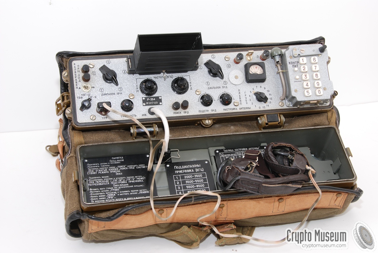
The R-354 was usually supplied in a canvas cover with two shoulder straps
that allowed it to be carried on the back. It was typically used in this
configuration by military personnel, and Special Forces (SF) in particular.
The manpack cover has various pockets in which the common supplies and
accessories were stored. Additional spares and accessories were available
separately.
|
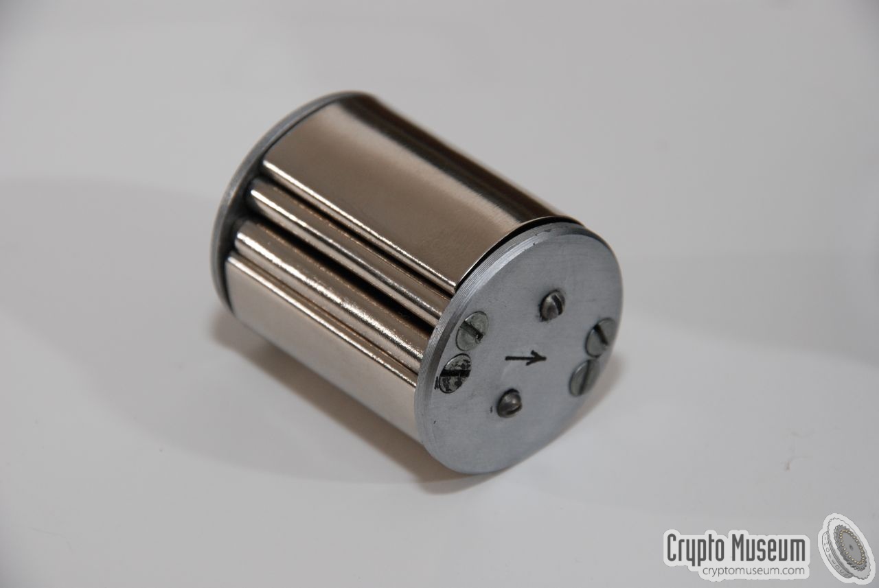
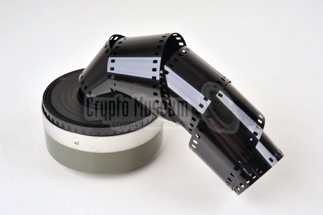
One of the most brilliant features of the R-354 is the fact that ordinary
35 mm photographic film is used for the burst transmitter, just like on the
earlier R-350 spy radio set.
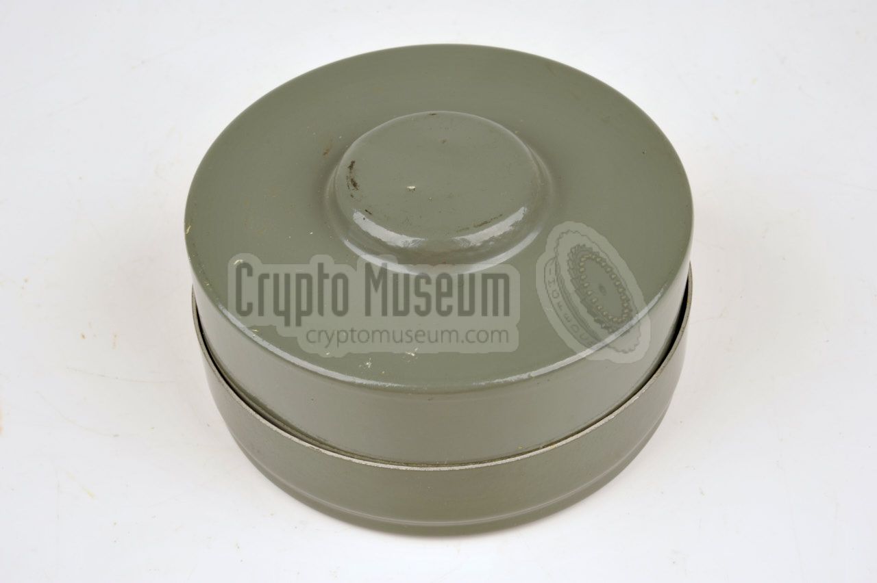
A cylindrical metal can with many metres of 35 mm film is supplied with the
set and is usually stored inside the top lid of the radio. This should be
sufficient for hundreds of short messages. The image on the right shows a
fully loaded film can. If more film was needed, the agent was able to buy
it anywhere in the world, without raising any questions. After all, it was
common film.
|
|
|
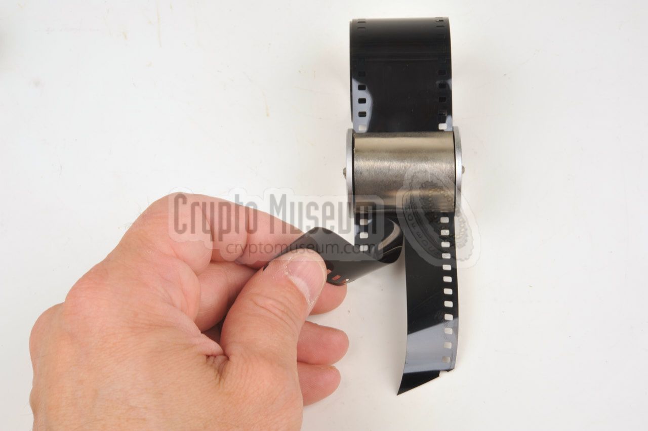
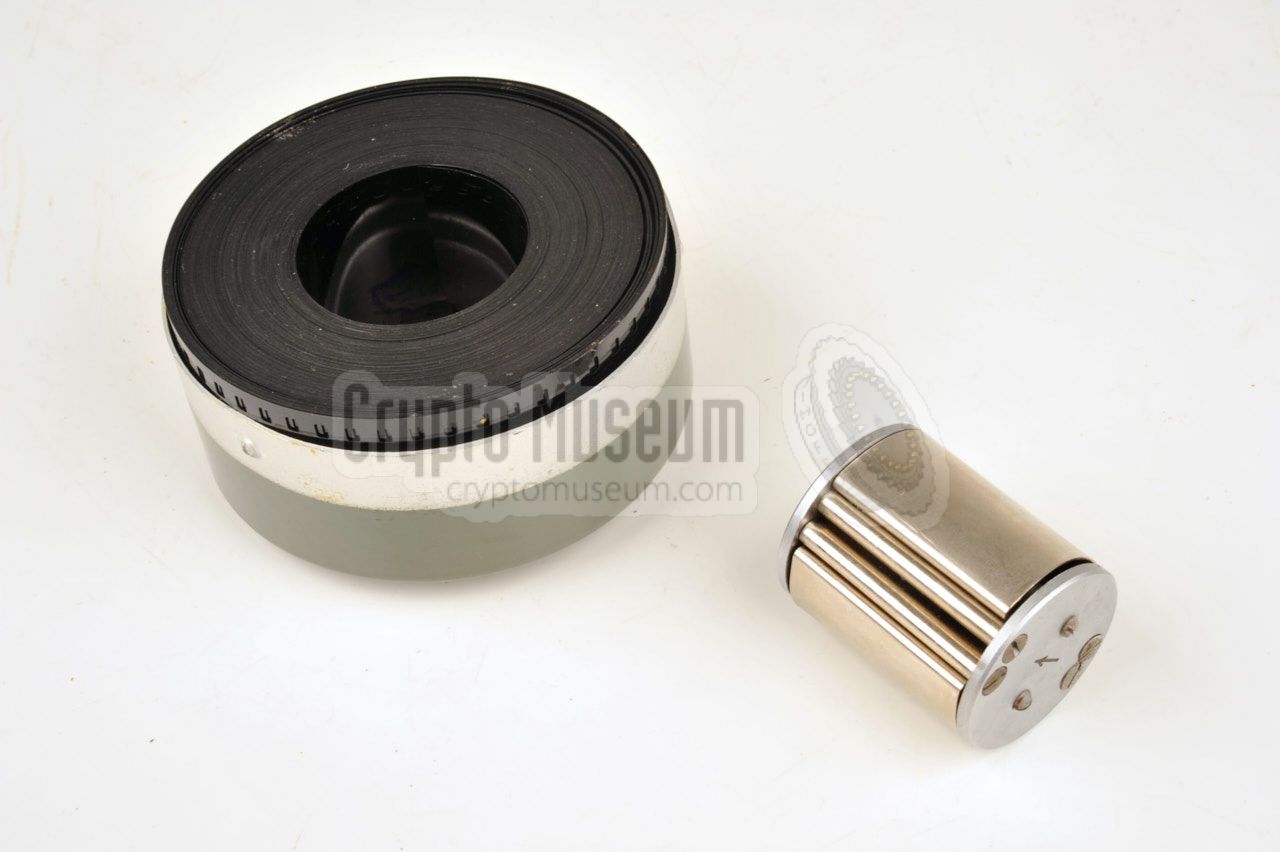
Unlike with the earlier R-350 spy radio set,
only half the width of the film
is needed on the R354. This means that the operator can send twice as many
messages with the same film supply. It also means that the film has to be
sliced in two halves before it can be used.
An appropriate film slicer was supplied with the radio set and was usually
stored inside the film can. For this reason, one side of the film can is
bulged somewhat. The image on the right shows how the slicer is used to split
the film in two.
|
|
|
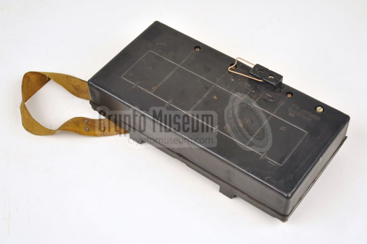
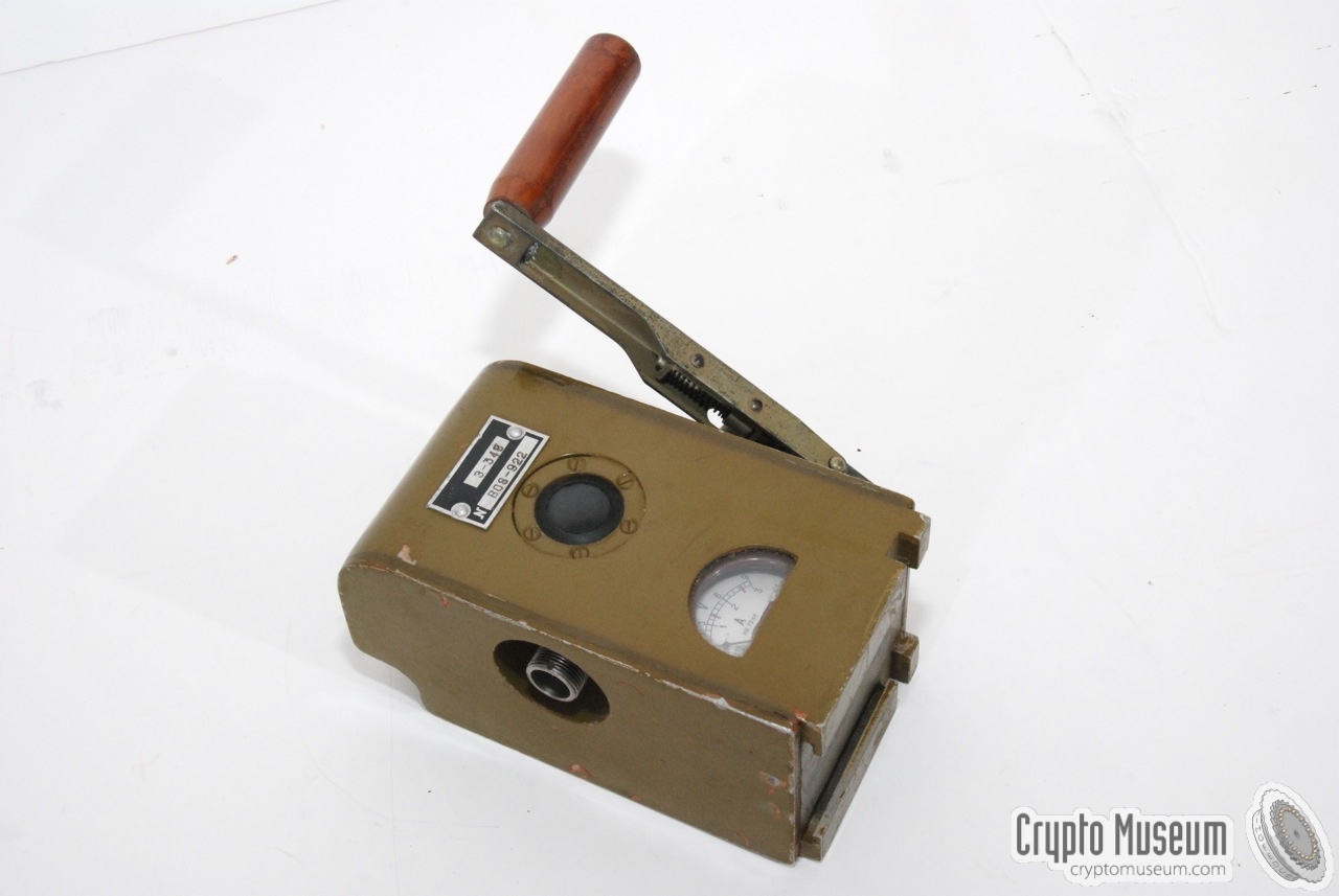
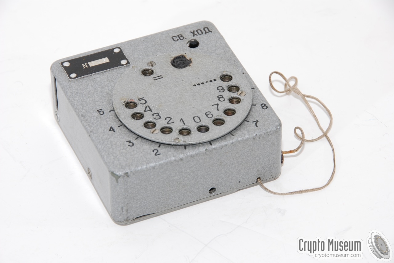
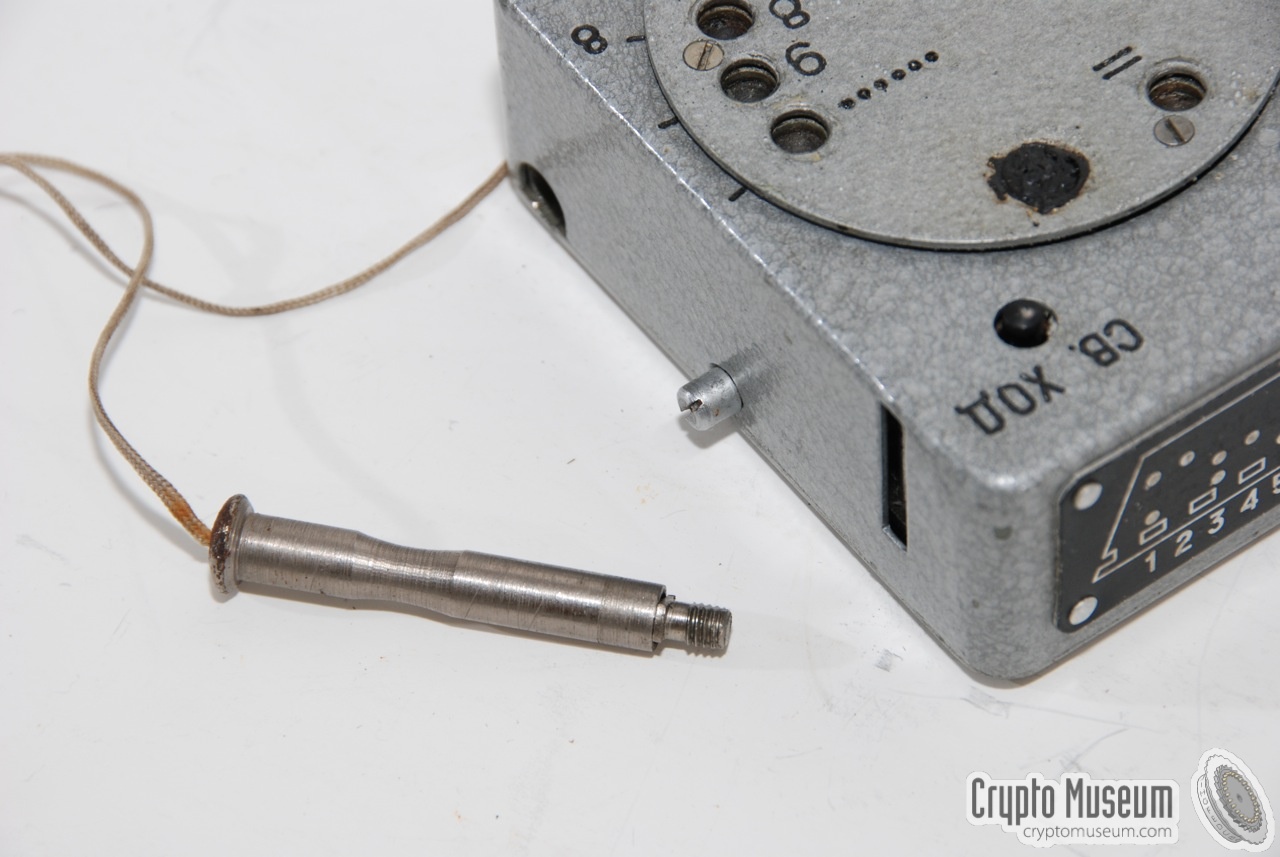
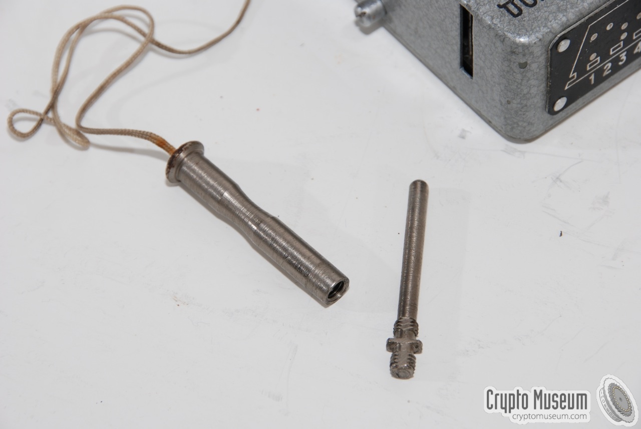
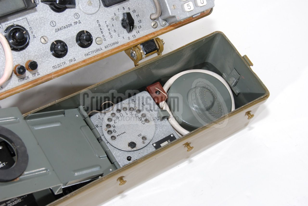
Initially, the R-354 was supplied with the film puncher shown here.
It is a rather bulky square device that is normally stored under a flap
in the top lid of the radio, aside the film container.
The film is fed through the puncher, and a pen (on a string) is
used to enter the digits of a pre-coded message on the rotating disc,
much like dialling a number on an old rotary telephone.
Each number is represented by a series of holes (rather than a single hole,
as on the R-350).
|
|
|
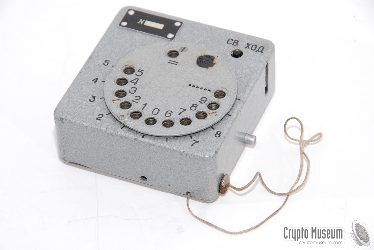
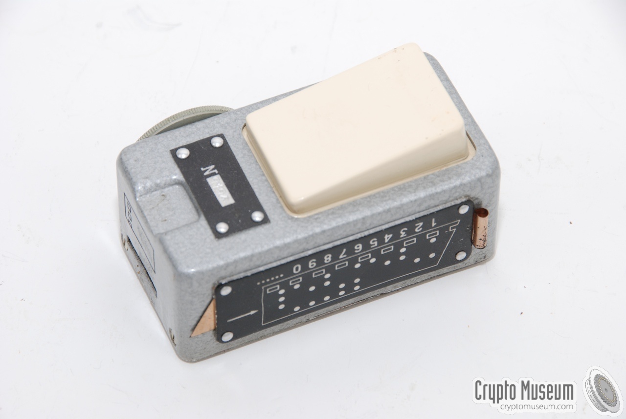
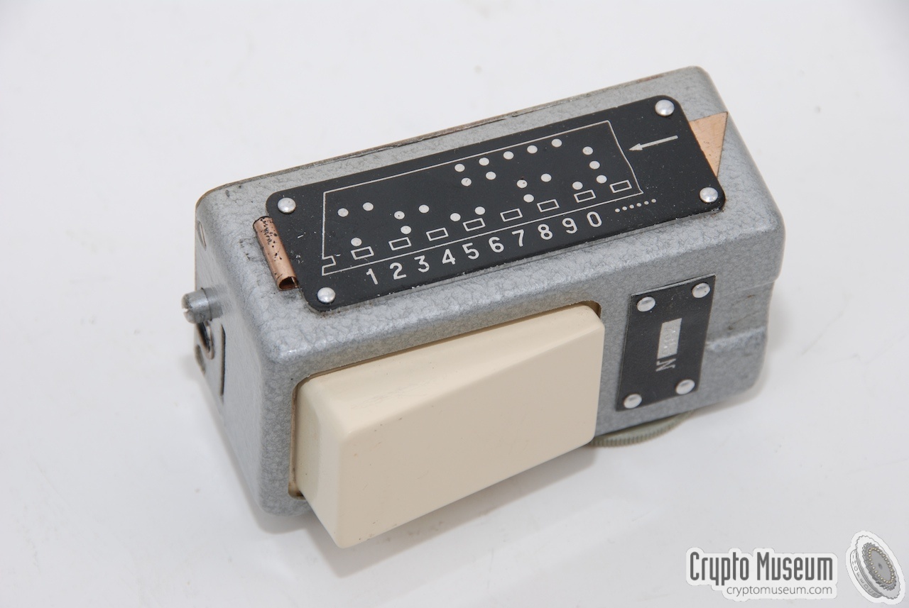
The rather bulky film puncher shown above,
was later replaced by the much smaller one shown here.
It fits nicely in one hand and is stored in the usual bay
of the radio's top lid.
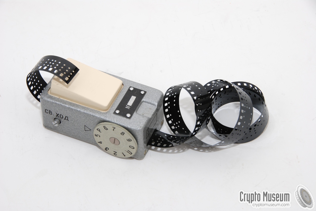
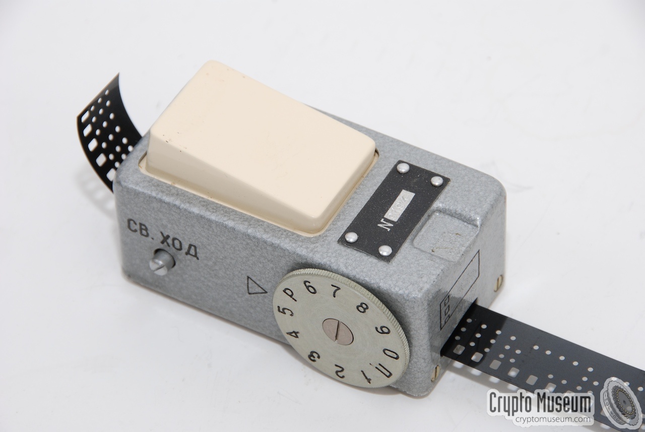
Punching the message works much like a dymo label printer. The wheel is
set to the required number, after which the large white button is pressed.
Each number is represented by a series of holes.
A small copper blade, hidden behind the
black instruction plate, can be used to clear the film path when it gets
obstructed.
|
|
|
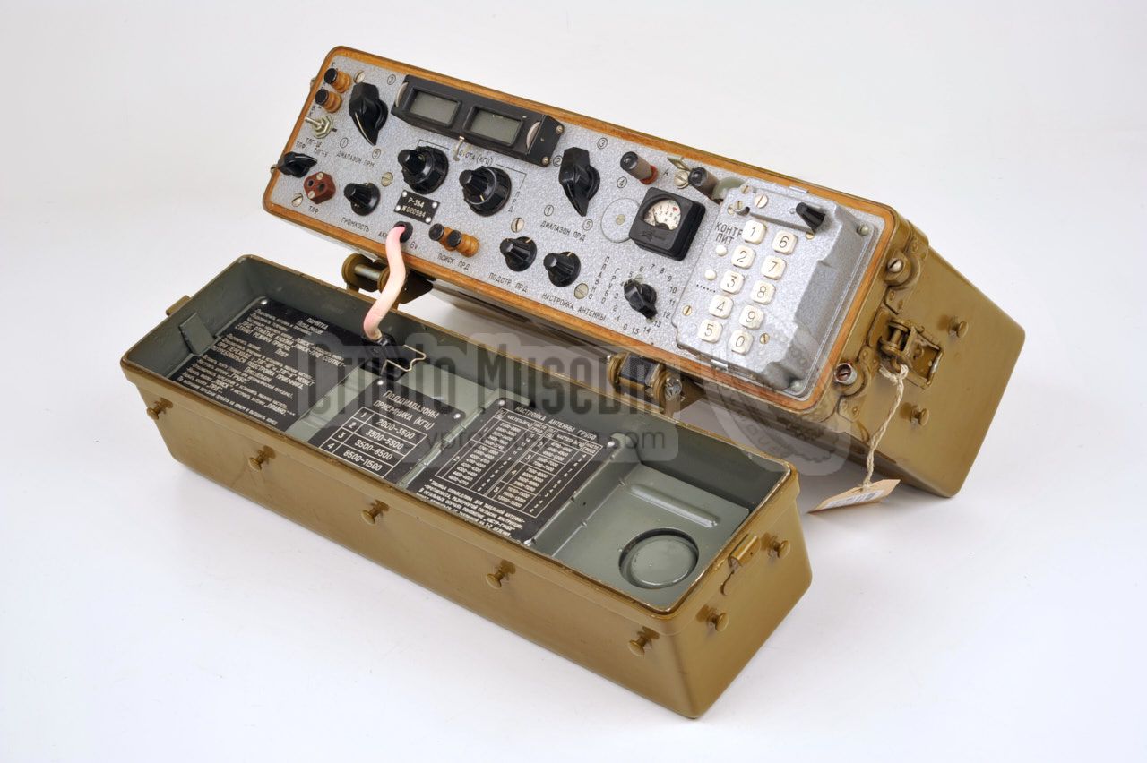
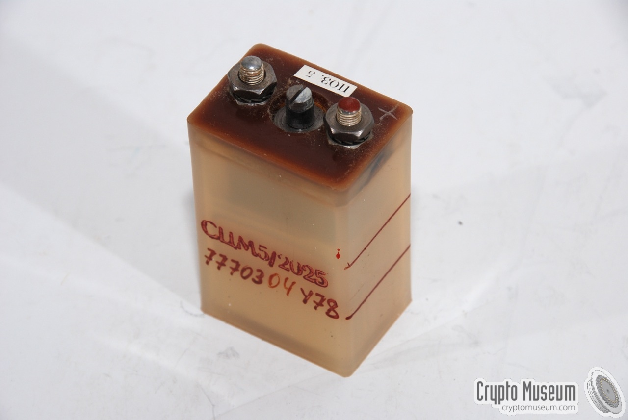
The R-354 was supplied with a so-called 6V 'wet' battery that was stored
inside the top lid of the radio, in such a way that the radio could be
connected to it by means of the short 6V DC cable running of the front panel.
As the R-354's transmitter is rather power-hungry, it can only be operated
for a short period of time, typically just 15 minutes, before the
battery has to be recharged again. For this reason, the R-354 was often
supplied with a hand generator, so that the battery could be recharged
between two sessions.
|
|
|
A short extension lead was supplied to allow the radio to be connected to an
external power source, or to connect the battery to a charger.
The extension lead is only about 50 cm long and has a two pin male plug at
one end, and a matching female plug at the other end. The lead is either stored
inside the manpack cover, or in the top lid of the radio,
in which case is was wound around the film container.
|
|
|
The battery of the R-354 lasted only a few minutes before it had to be
recharged again. Recharging was usually done with a hand generator
or a small mains charger.
Alternatively, the battery could be charged from a standard car battery,
using the supplied battery charger cable shown on the right.
|
|
|
As the projection scale of the R-354 produces a rather faint image,
a foldable hood was supplied that could be fitted in front of the
display, thereby effectively blocking any sunlight.
The hood was normally folded and stored inside the large pocket
of the back pack (at the rear). The images below show how the hood
was used. It was mounted over the display in such a way that both
frequency adjustment thumbwheels were left free.
Note that the viewer is not present with the Czech version of the
radio (R-354/CZ).
|
|
|
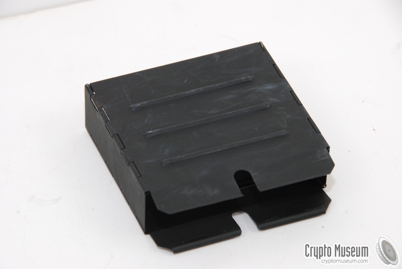
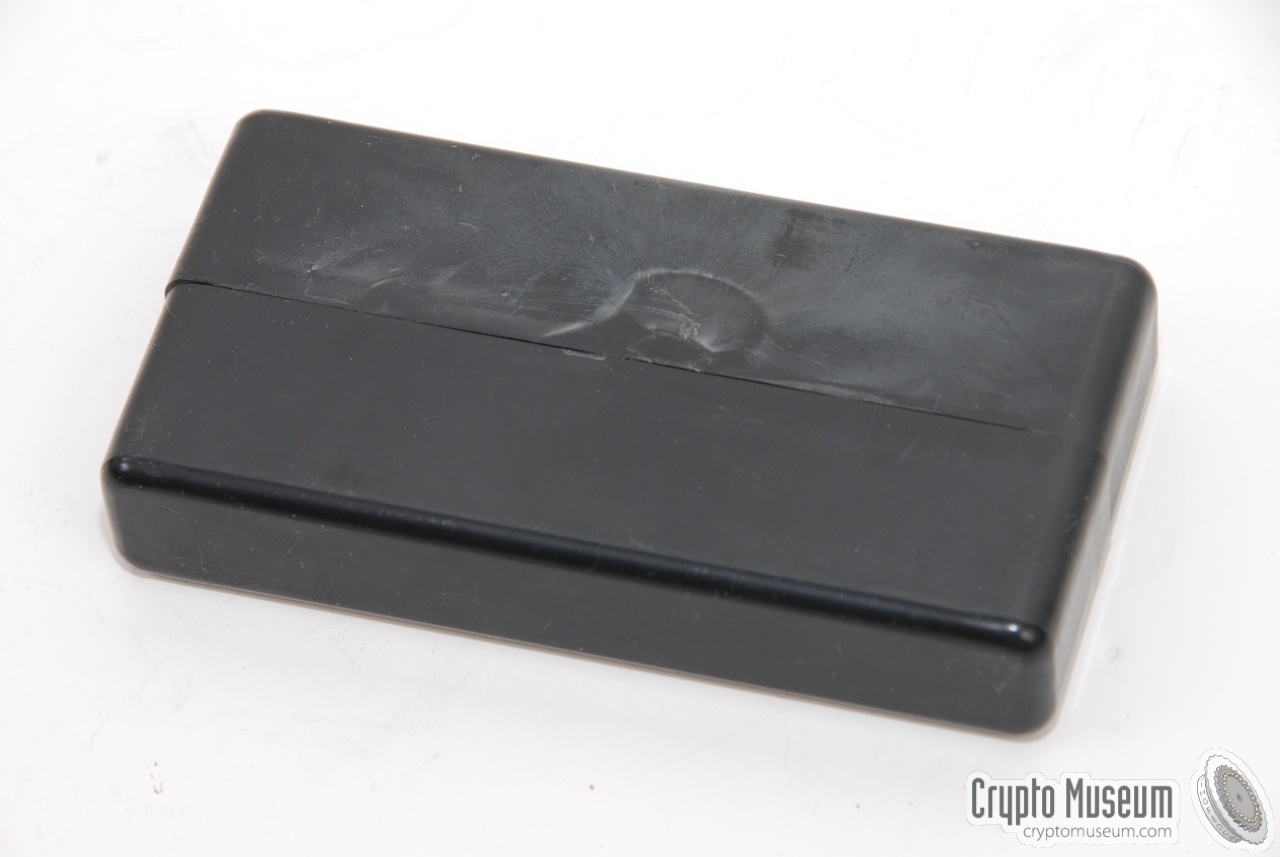
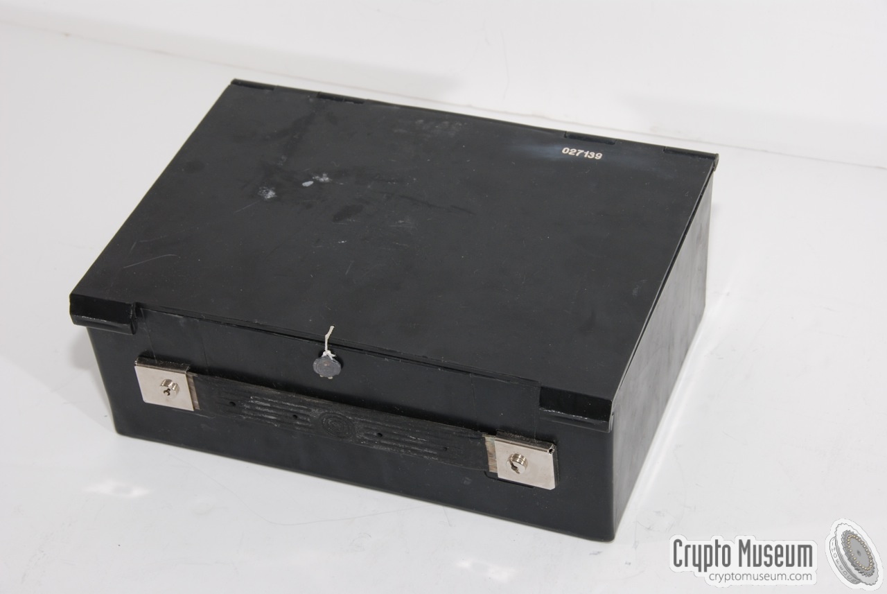
Sometimes a small plastic box with some spares (consumables) is supplied
with the radio. If it is present, it is usually packed inside one of the
pockets of the back pack.
The box contains several light bulbs, fuses and a piece of insulation tape.
As far as we know, the boxes were either black or white (see below).
|
|
|
|
|
Spare parts and accessories
|
|
|
|
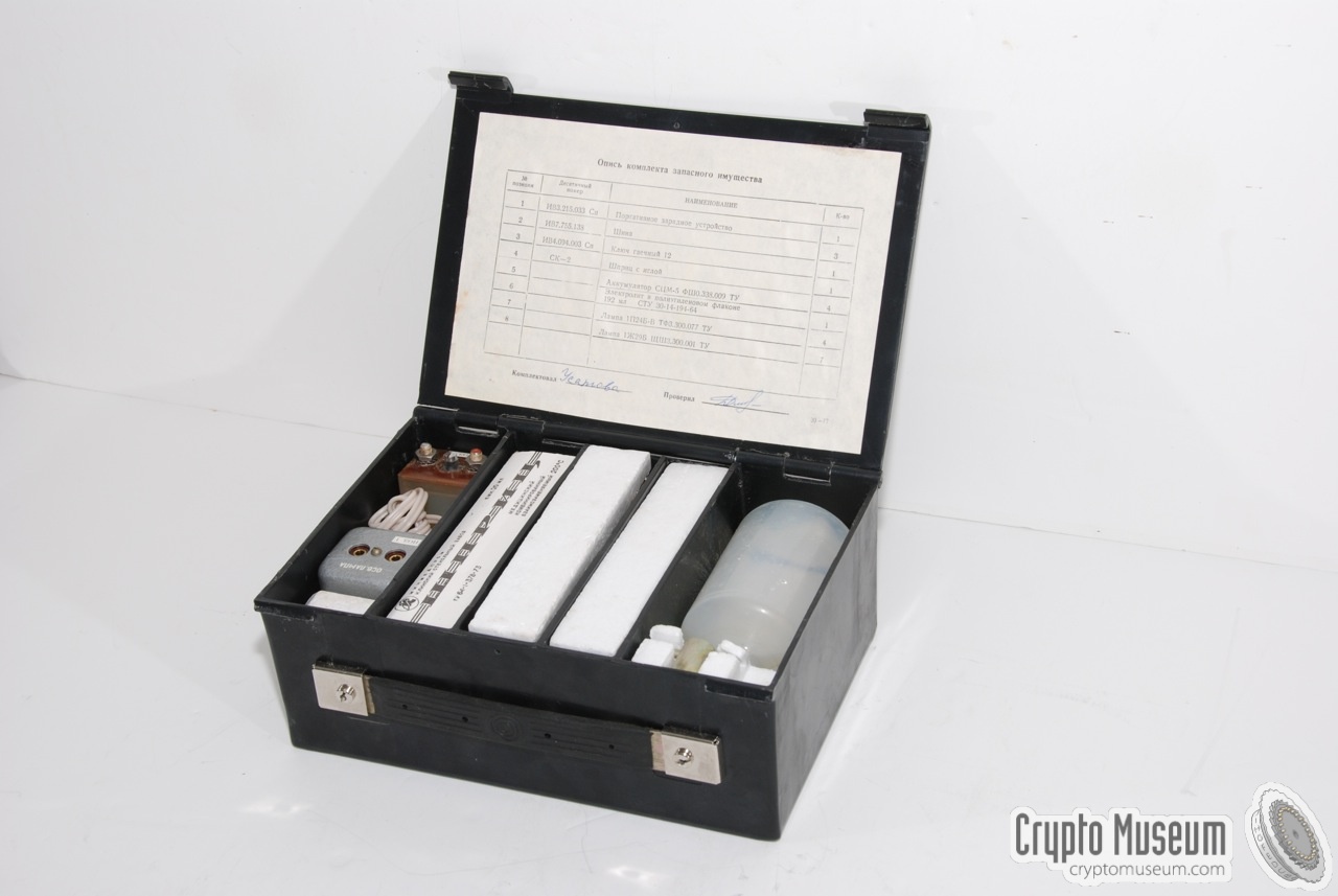
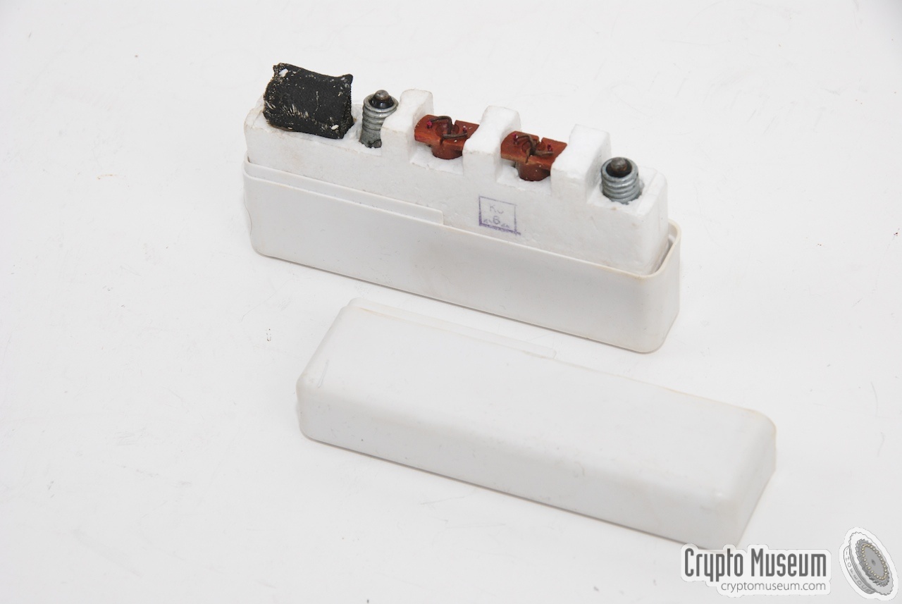
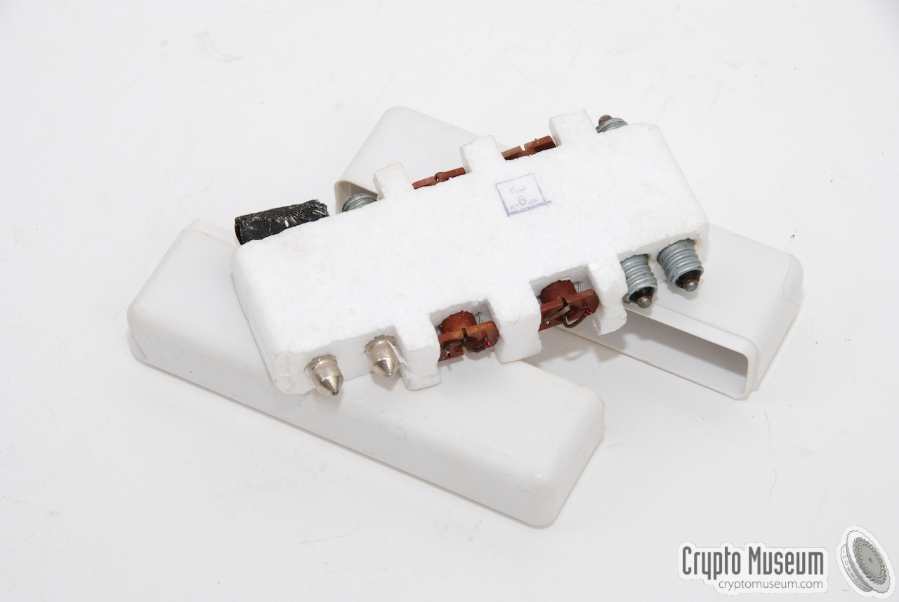
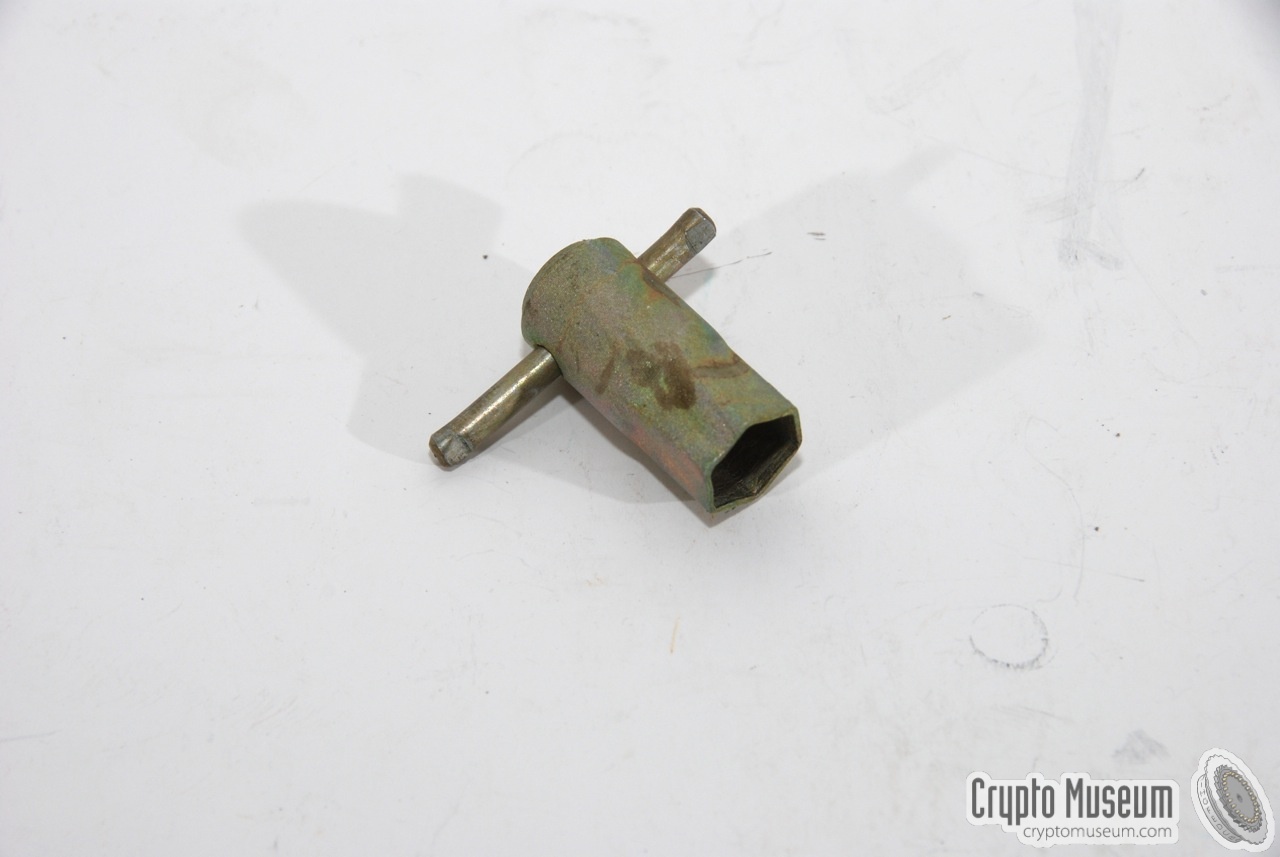
Some R-354 radio sets were supplied with a small bakelite box containing a number
of spare parts, accessories and consumables. A checklist, glued inside the lid of
the box, shows which items should be present. Please note that at least two
different layouts of the spares box exist.
|
The box shown here contains the
following items:
- 4 rechargable batteries
- Battery fluid (container)
- Hex key
- Syringe
- Spare valves (tubes)
- Mains battery charger
|
|
|
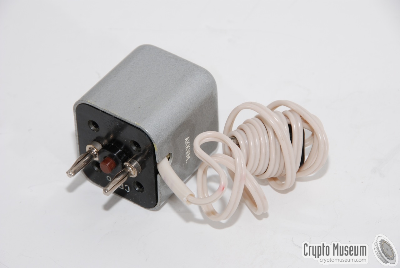
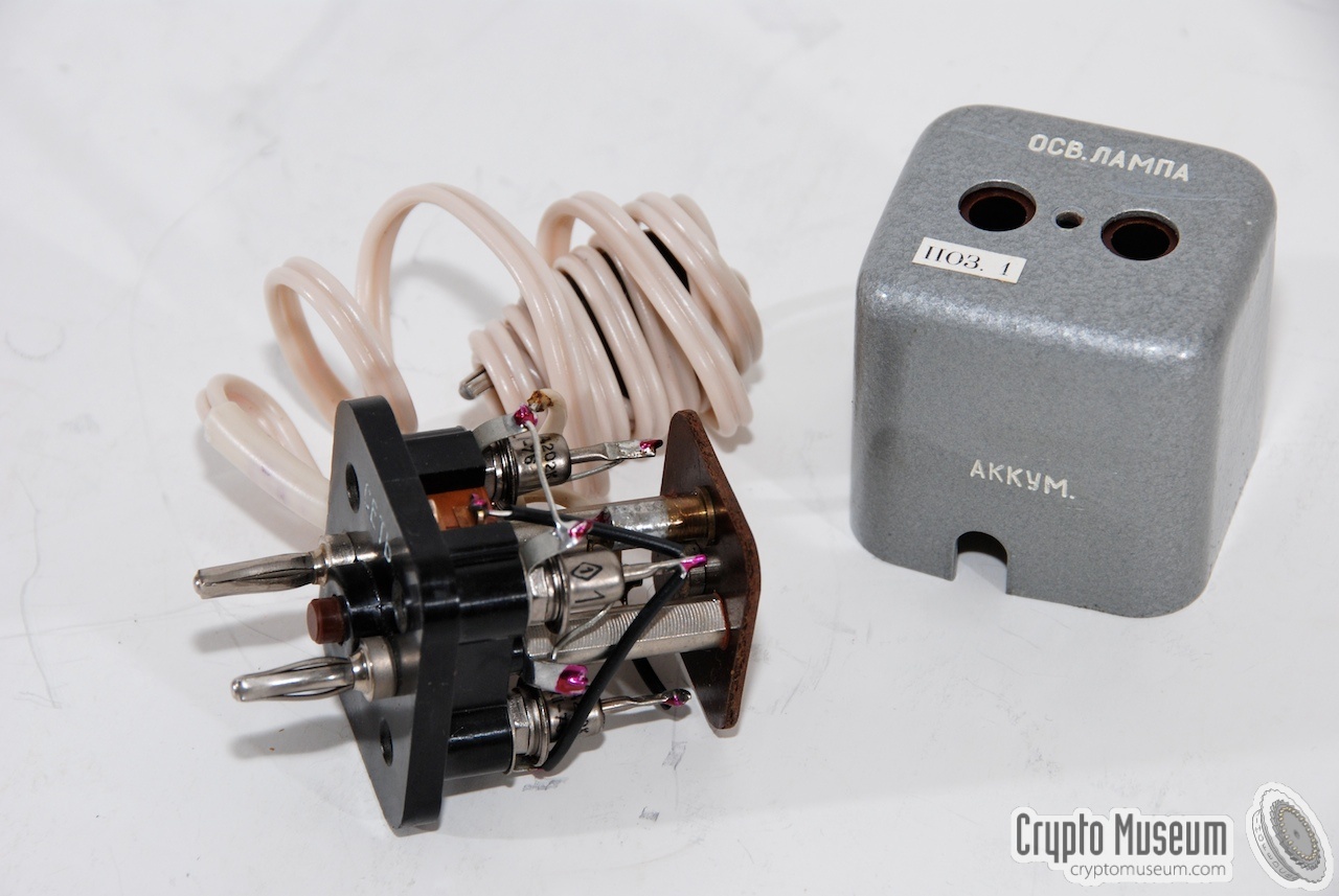
A rather small mains adapter was supplied with the accessory kit (shown above).
It's a small grey cubical box that can be plugged straight into a mains socket.
At the back of the unit is a standard mains socket that allows a common mains
light bulb to be connected. When connected to the battery, the lamp acts as a
current limiter.
|
|
|
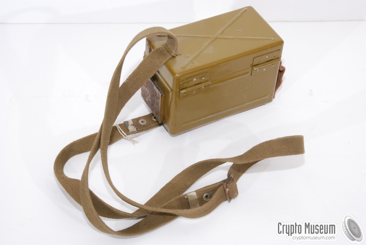
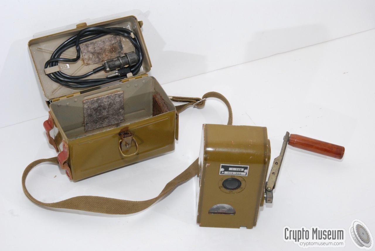
If no mains power is available, the battery can also be charged with a small
crank-operated power generator. Charging the batteries is not an easy task and
takes several hours, for just a few minutes of operation.
The generator is normally stored inside a carrying case with a canvas strap.
The power cables are stored inside the top lid of the case.
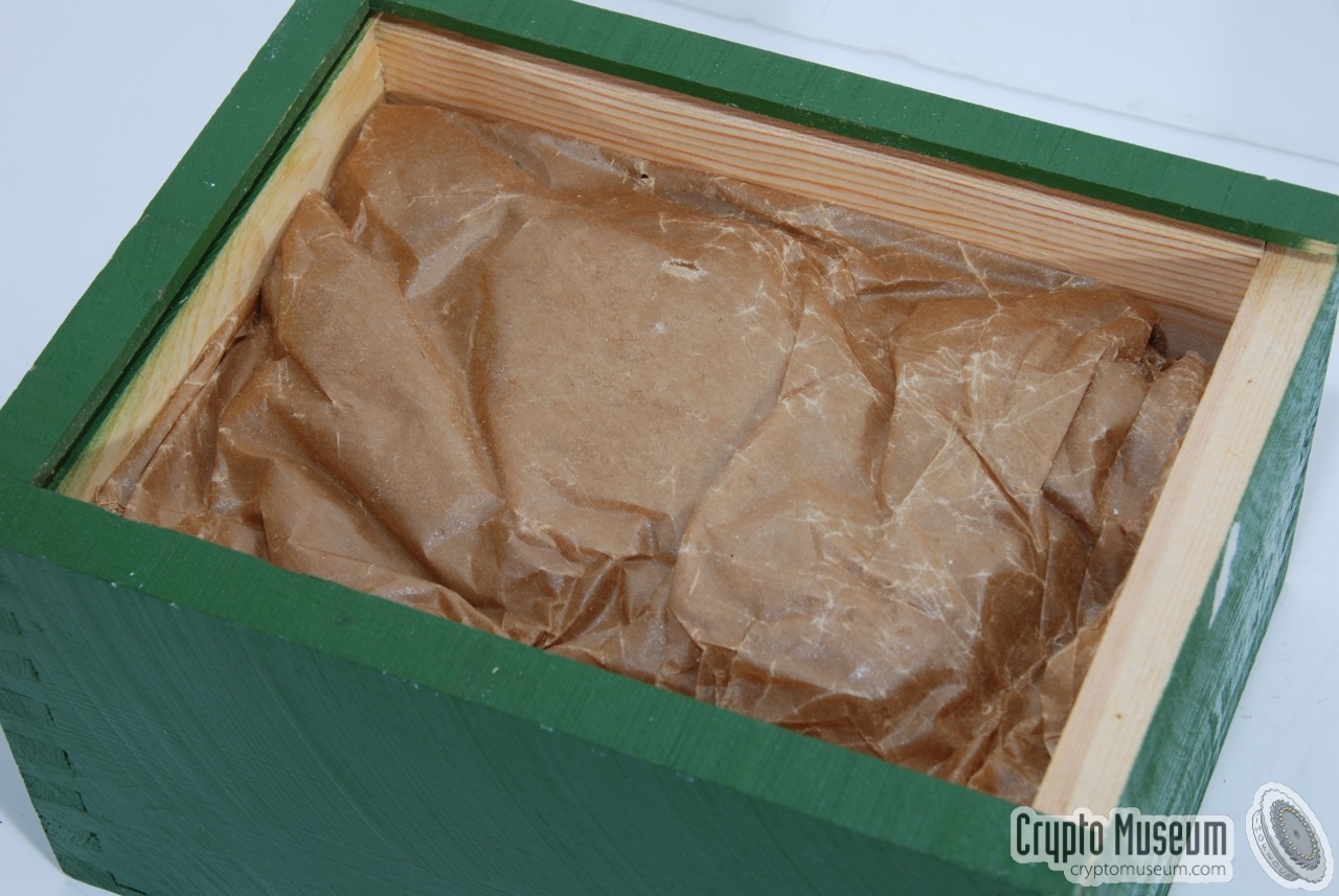
New generators were generally supplied in grease paper, stored inside in a green
wooden box, together with a checklist and instructions.
|
|
|
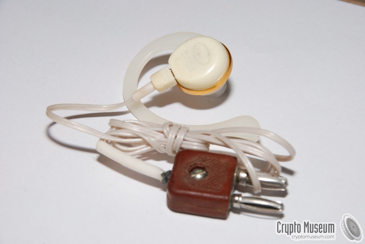
Almost any type of headset can be used with the R-354.
In most cases, a common USSR military headset was supplied, with rubber ear
pads and elastic head bands. Such headsets are commonly used with military
radio sets in tanks etc., as they can be worn under a helmet.
The headsets is connected to the two-pin socket on
at the far left of the radio's front panel.
Some sets were used with a small earpiece
such as the one shown below.
|
|
|
For proper operation of the transmitter and the receiver,
it is important that a long wire antenna and a suitable
counterpoise are connected to the radio. A suitable wire antenna
is supplied with the set and is usually stored inside one of the pockets
of the manpack cover.
The image on the right shows the antenna that was typically supplied with the
set. It has a nylon fishing line with a throwing weight at the end, that allows
the antenna to be fitted in between two trees easily. Instruction for
setting up and tuning the antenna are provided in the manual.
|
|
|
To ensure that the antenna wire is as free as possible from ground and obstacles,
one or two supporting masts are supplied with the radio. These masts are usually
stored inside a canvas bag that is strapped to the bottom of the radio.
The mast is constructed of glass fibre and consists of several telescopic segments.
It is light weight and can be erected in seconds.
|
|
|
When the R-354 was used in a military context, which was usually the case,
it had its own canvas 'raincoat' with pockets for the accessories.
It has two strong shoulder straps that allow the entire radio
station to be carried on the back.
The canvas raincoat also protects the radio against the environment and is
padded to make carrying slightly more comfortable for the radio operator.
The image on the right shows a typical canvas manpack cover. It is attached
to metal nails on the circumference of the radio.
|
|
|
Provisions have been made to allow an R-354 radio station to be dropped-off by
parachute. This was considered useful when supplying army troups,
Special Forces (SF) (operating behind enemy lines), resistance groups
and agents.
The image on the right shows a typical R-354 parachute bag in exceptionally
good 'as new' condition, with all of its padding still intact.
In practice, the padding of the surviving parachute bags has commonly
decomposed after many years of storage.
|
|
|
Each R-354 was supplied with a set of manuals, complete with user instructions,
circuit diagrams and maintenance information. In some cases, maintenance
logbooks or passports for the radio and the batteries were also present.
In practice, original manuals in the Russian language are extremely rare,
but thanks to Bjorn Forsberg [A], we now have them available:
➤ Download manual
➤ Download circuit diagrams
|
|
|
|
Although the R-354 is rather heavy, it is a well constructed electronic hybrid
that shows the clever combination of valves (tubes), transistors and digital building
blocks. After loosening the four large bolts at the sides of the front panel,
the radio can be lifted from its enclosure.
|
All building blocks are mounted to the front panel, so that the
radio remains fully operational when being serviced.
At the top are a tuning capacitor, a band selector,
the antenna tuner and part of the power supply.
Left of the center are the two projection scales.
At the far right is the digital block that holds the burst transmitter.
At the bottom are the smaller electronic circuits,
like the various stages of the receiver.
Although transistors are used at various places inside the R-354,
some of the more critical circuits are still built around sub-miniature
values (tubes).
|
|
|
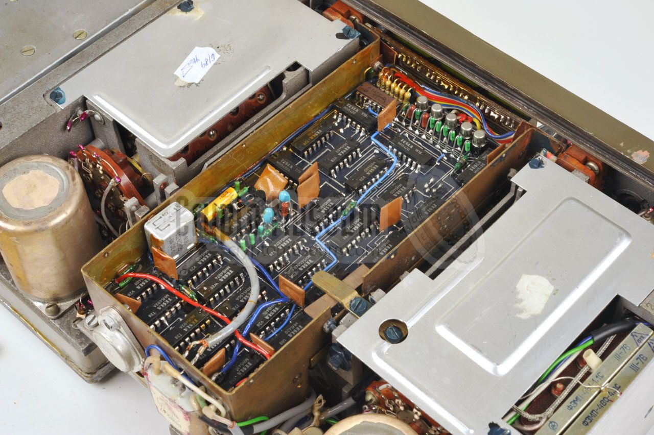
The radio is beautifully compartmented,
using a die-cast aluminium alloy frame to hold the various circuit
boards at the bottom. Also at the bottom is the remaining part of the
power supply. To the left of the power supply
is the transmitter PA-stage,
consisting of three sub-miniature valves connected in parallel.
At the far right of the front panel is the key panel with its
integrated film reader. Behind the switches is a
nice die-cast assembly with the micro switches.
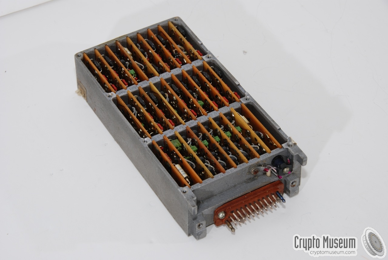
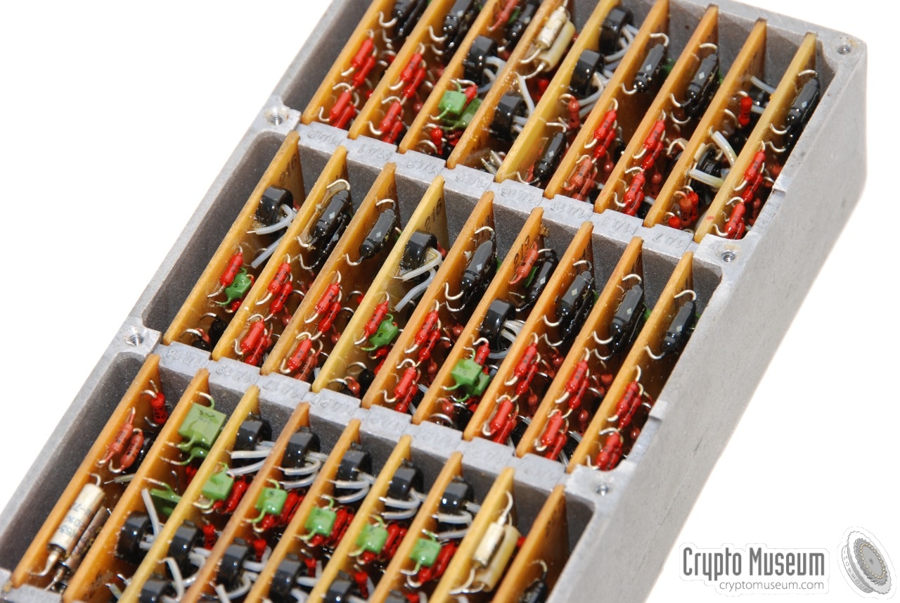
To the rear of the film reader is the actual burst transmitter that
is housed in a
large rectangular aluminium sub-assembly.
Inside the block are 27 small PCBs,
each of which contains a digital circuit. The block connects
to the film reader by means of a 31-pin connector at the front.
|
|
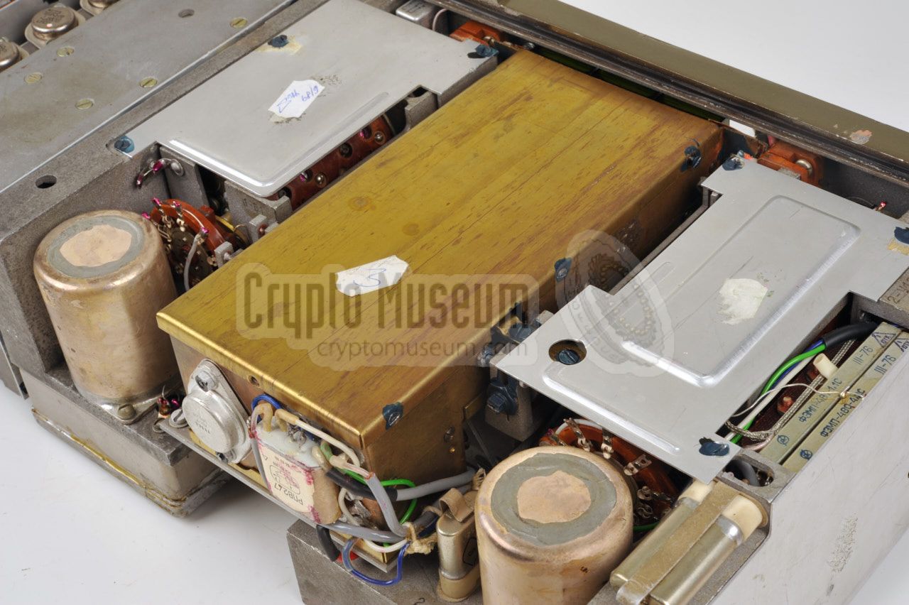
The Czech version of the R-354 is largely identical to the standard version.
In fact is is a standard version which was modified at the
Tesla factory
[3] in the mid-1970s. As part of the modification,
the projection scales were removed and their space was used
to accomodate a digital readout.
|
The modification consists of a brass box that is fitted in the
space that was previously used by the projection scales. A large power
transistor and a relay are fitted to the rear of the box. The box is open
at the front, so that the displays are visible though the windows
in the front panel.
The circuit is mainly built with Tesla
parts, such as the MH5400 series ICs,
which are the military variants of the well-known 7400 family [4].
In order to reduce power consumption, the displays are disabled by default
and the user has to press one of the calibration buttons to enable them.
|
|
|
Pressing the upper calibration button will cause the display to show the
current receive frequency (RX). The left window will show the MHz part of the
frequency, whilst the kHz part will be visible through the right window.
In the same way, the lower calibration button should be pressed to monitor
the TX frequency.
The TX and RX frequencies are both free running and can be altered
in the usual way by turning the dials below the display.
The display is merely a frequency counter.
|
- Power Supply: 6 Volt, 3-8 Amp.
- Frequency range: 2.5 - 15 MHz (in 5 ranges)
- Modulation: A1A, A3A
- TX Power Output: 10 Watt (CW)
- Range: 1500 km
- Weight: 12 kg
|
-
Original scanned manual kindly supplied by Bjorn Forsberg.
-
Scanned by Crypto Museum, 1 October 2023.
|
|
|
|
Any links shown in red are currently unavailable.
If you like the information on this website, why not make a donation?
© Crypto Museum. Created: Friday 04 December 2009. Last changed: Tuesday, 04 March 2025 - 11:31 CET.
|
|

|
|
|