|
|
|
|
|

|
|
WWII RX NL Oranje
Clandestine midget receiver · Radio Oranje
Panter 1 was a clandestine single-valve receiver
for the Long Wave (LW) radio band, built during
World War II (WWII) by amateur radio operator MP (Mart) Rooth
(callsign: PA0MPR) in Rotterdam (Netherlands). It was used to clandestinely
listen to the British Broadcasting Corporation (BBC)
on 1500 metres (200 kHz), and in particular to the programs of the
Dutch government in exile that were aired daily by the BBC European Service
under the name Radio Oranje (Radio Orange). 2
|
|
It is one of the simplest and smallest designs of a clandestine radio of
WWII. It uses just one valve and – interestingly – it uses just one DC
power voltage – 4V – that was supplied by an external battery or a
flashlight (4.5V).
A cable with Edison E10 thread at one end is
present to 'steal' the power from a flashlight by screwing the E10-end
directly into the flashlight's E10 lamp fitting.
|
The valve – a simple triode – is used way outside its specified
range and produces only a weak signal into a
pair of high impedance (4000Ω) headphones,
that are connected to the banana sockets at the left edge.
The two banana sockets at the right edge are for antenna and ground.
During WWII, the Germans had made it illegal to listen to foreign radio
stations. As most people ignored this, the Germans issued a directive
on 13 May 1943 that made it illegal to possess a receiver. People who
didn't hand in their radio, risked high fines or even the death penalty.
|
|
|
|
The receiver shown here is part of a series of three different designs, all
built by amateur radio operator Mart Rooth (PA0MPR) in Rotterdam (Netherlands)
during WWII, and based on the same circuit diagram.
The other two are housed in a small wooden cube and a
matchbox respectively.
|
-
As this homemade device does not have a name, we have nicknamed it
Panter after the brand name of the cigar box it is housed in.
An identical receiver from the same maker has also been found inside
a (same-size) cigar box with the brand name Radio [2].
-
Named after the Dutch monarchy's House of Orange-Nassau. ➤ More
|
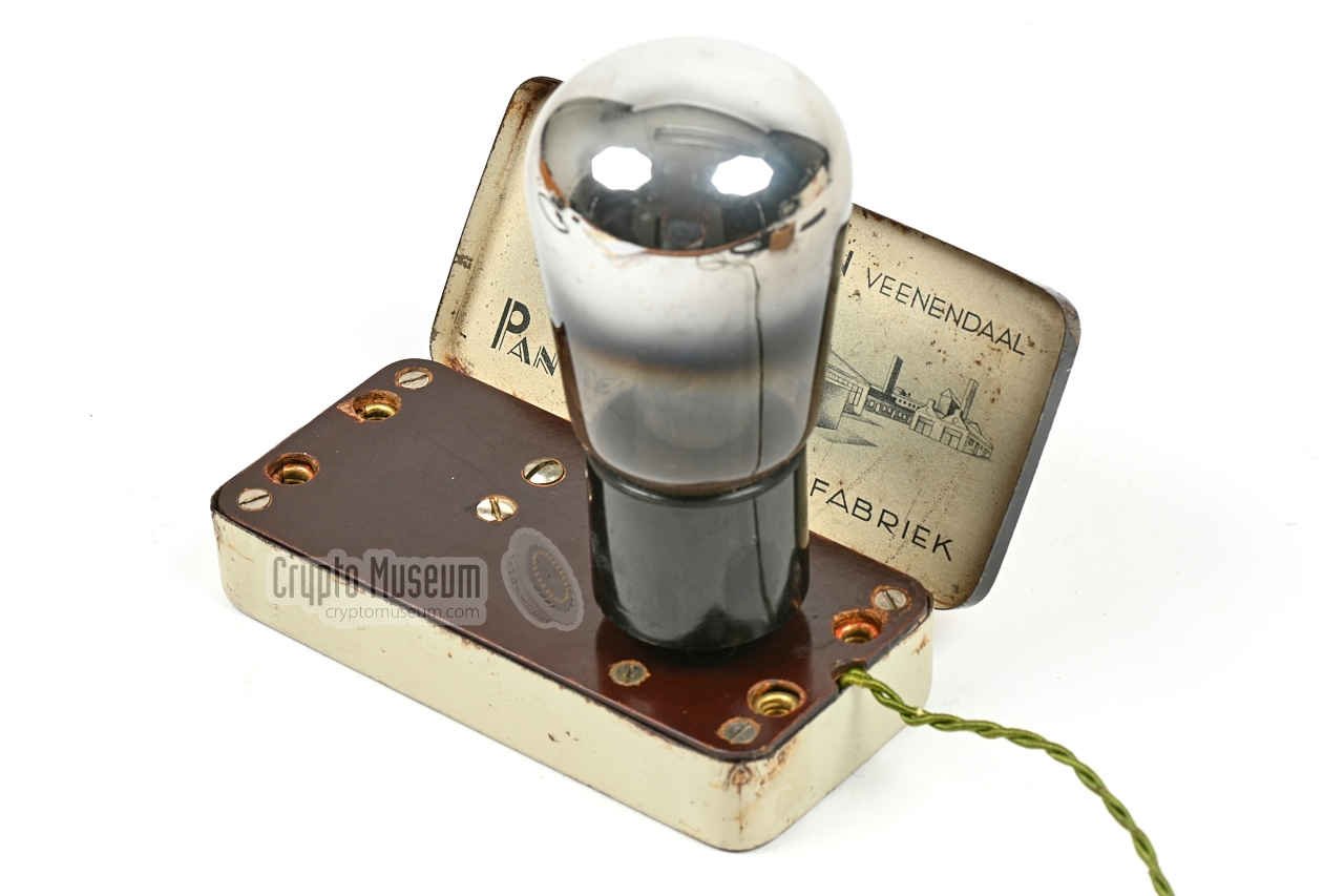
The image below shows how the Panter receiver was used. The receiver
was first removed from the metal cigar box. The cable was then unrolled and
the receiver was put back in the cigar box. Next, the valve was installed in
the 4-pin socket and a pair of high-impedance headphones was connected.
A long wire – often hidden under the rooftop of the house – was used as
the antenna, whilst the ground terminal was connected to the earth
— usually the metal pipe of the water tap.
Power was provided by an external rechargeable 4V battery, or by the 4.5V
battery of a flashlight. In the latter case, the existing lamp was removed
from the flashlight and an adapter cable was
fitted in its place. The adapter cable was then
connected to the power terminals of the receiver.
|
Below is the circuit diagram of the receiver, as it was found inside a
similar Radio Oranje receiver from the same maker and featured chapter 12
of Louis Meulstee's
Wireless for the Warrier Volume 4 - Supplement
[2].
This circuit has been verified against the actual device featured here.
It is a regenerative receiver with a space-charge detector (V1) and a
feedback coil (L2) – connected in series with the anode of V1 – that is
located above the coil (L2) of the tuned circuit (L1/C2). The feedback
coil (L1) can be positioned with a screw, so
that the regeneration level is adjustable.
What makes this design special, is the fact that a single 4V DC power
supply is used both for the filaments and the anode. Although this is
much lower than the minimum specified anode voltage of 50V [5], it
actually works. This is done by using the valve in space charge mode
[3][6][7].
Low-cost designs like this, were very popular
in the 1930s, as they did not require HT voltages [4].
|
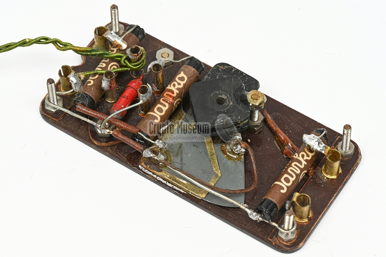
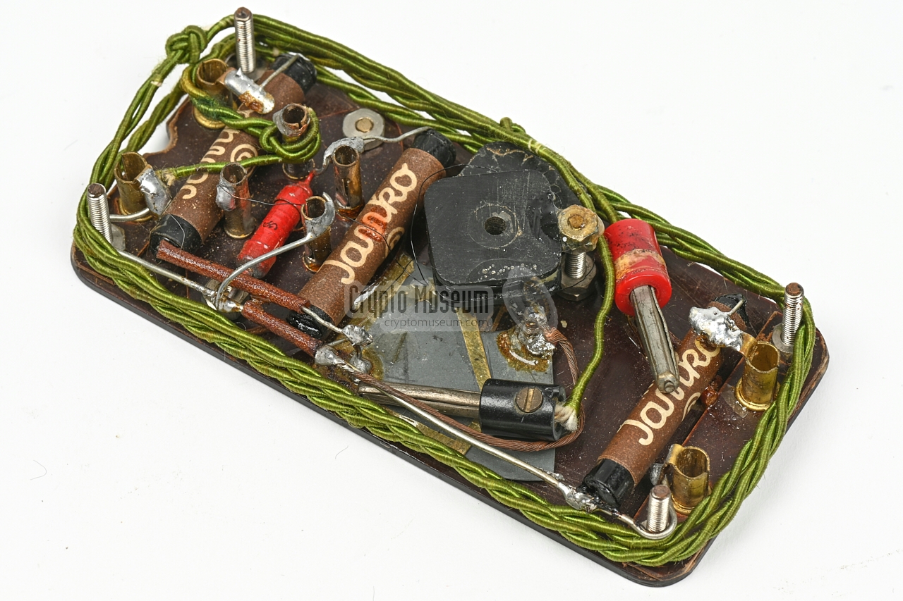
The interior of the receiver can be accessed simply by holding opening
the metal cigar box and holding it upside down. With some help, the
interior should come out. The image below shows a bottom view of it.
All passive parts are mounted to the bottom side of the brown pertinax panel.
At the four corners are 3 mm screws that act as spacers. They ensure that
pertiax panel lines up with the metal cigar box, and prevents contact
between the metal parts and the bottom panel of the cigar box.
For extra isolation, a piece of thick black paper is present at the bottom
of the box.
At the heart of the receiver are two movable parts: a homemade adjustable
capacitor (C2) and movable coil (L2), each of which are adjustable from the
top surface. C1 is used to adjust the frequency, whilst L2 is just to adjust
the regeneration level. The valve (V1) is installed at the top.
|
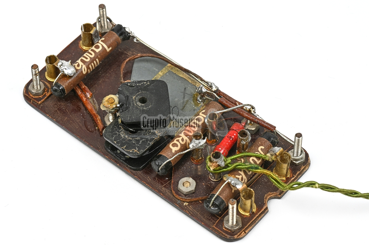
When we obtained the receiver in March 2021 [1], it was in well-preserved
condition, with the original wartime parts still present.
The only problem was that the
movable coil (L2) had come off
the rotatable shaft and was floating
around inside the case. This was probably caused by frequent
handling of the device in the 76+ years that had passed since the war.
As this would eventually cause the thin wires of the
coil to break, it was necessary to refit the coil to the rotatable shaft.
In the original situation the coil was held in place by hot wax or paraffine,
but this does not offer a long term solution, especially when the device is
kept under varying environmental conditions (hot, cold, moisture, etc.).
For this reason we cleaned the shaft and the body of the coil, and applied a
small drop of a modern two-component adhesive. The result is shown in the
images above. The radio has since been tested with a signal generator and is
now fully operational again.
|
- Movable coil (L2) refitted to the axle
|
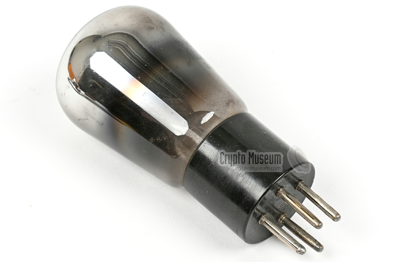
B405 was a 4-pin directly-heated triode valve (tube) with a 4V filament,
introduced by Philips in 1927 for use in pre-amplifier and/or
power amplifier stages. It has an anode voltage range of 50-150V,
but could also be used in space-charge mode, with an anode
voltage of just 4V [6][7]. The regenerative single-valve receiver
featured above, uses the valve in this mode.
Below is the pinout of the B405 as seen from the bottom.
Usable alternatives are the A415, A425 and B415.
➤ B405 datasheet
|
Device Radio receiver Purpose Clandestine reception of Radio Oranje via the BBC Era WWII Years 1943-1944 (est.) Purpose Reception of BBC broadcasts at 200 kHz (1500 m) User(s) Civilians (clandestine) Band Long Wave (LW) Frequency 160-200 kHz (1500 - 1875 m) Design MP (Mart) Rooth (PA0MPR) Principle TRF with reaction Valve B405 or similar Power 4V from battery or flashlight (4.5V) Output High impedance headphones (2000-4000Ω) Dimensions 106 x 53 x 19 mm Weight 98 grams (bare receiver, without valve)
|
- Metal cigar box for 10 mignor cigars (branded 'Panter')
- Receiver base unit (fitted inside cigar box)
- Valve B5405 or similar
- Headphones (4000&Ω) with 2-pin plug
- Power cable with E10 fitting (optional)
- Antenna and ground leads
|
- Cor Moerman, Miniature Radio Orange receiver in Panter cigar box - THANKS !
March 2021.
- Louis Meulstee, Clandestine Midget Receivers #5
Wireless for the Warrier,
Volume 4, Supplement chapter 12.
Version 1.00 may 2015.
- Jeff Duntemann, Low-Voltage Tubes — Low-Voltage Operation with ordinary tubes 1
Retrieved September 2021.
- One-Tube Set Works on Six Flashlight Cells 1
Popular Mechanics, September 1936. pp. 420-421.
- Philips Miniwatt B 405 (datasheet)
Philips, date unknown.
- Wikipedia, Vacuum tube — Space charge of a vacuum tube
Retrieved September 2021.
- Wikipedia, Space charge
Retrieved September 2021.
- Peter Kievits (PE1RUF), Personal correspondence
September 2021.
|
-
Brought to our attention by Peter Kievits [8].
|
|
|
|
Any links shown in red are currently unavailable.
If you like the information on this website, why not make a donation?
© Crypto Museum. Created: Monday 04 January 2021. Last changed: Wednesday, 05 November 2025 - 12:08 CET.
|
 |

|
|
|


