|
|
|
|
|

|
|
Finland Sweden Kyynel M-7 →
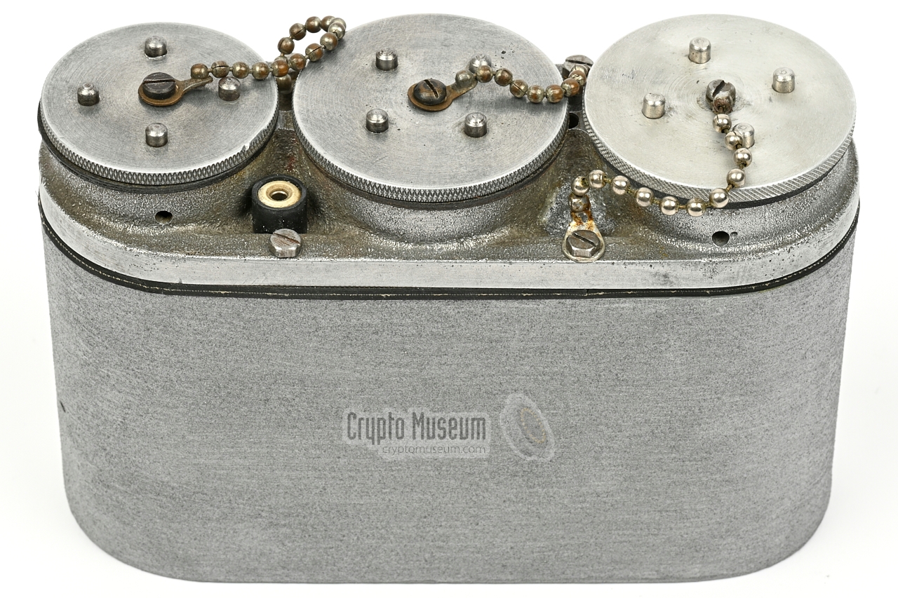
The M-5 is housed in a die-cast aluminium enclosure that measures
150 x 100 x 56 mm and weighs 550 grams. It is watertight, so that
it can be stored for a longer period of time in an underground cache
or even under water. At the top are the controls and connections,
hidden underneath three removable watertight caps.
The device is a single-valve (tube) free-running oscillator that operates
between 3.5 and 6 MHz and produces an output power of 500 mW.
The image on the right shows a typical M-5 unit in its watertight die-cast
aluminium enclosure.
|
|
|
The unit is powered by 1.5V DC (LT) and 120V DC (HT), either from a
battery pack or an external power supply unit (PSU). Two reels with 21 m long
wires were used as a symmetric antenna. The wires could be shorted to match
higher frequencies. Also supplied was a miniature morse key.
Some devices had a socket for connection of the receiver, allowing them
to share the antenna.
Based on surviving serial numbers,
it is likely that no more than 100 units were manufactured.
The design of the M-5 transmitter was later also used
in the Kyynel M-10 and M-11 radio sets.
➤ History of the Kyynel radio sets
|
-
In cooperation with other radio amateurs.
➤ More
-
Kyynel is the Finnish word for tear.
|
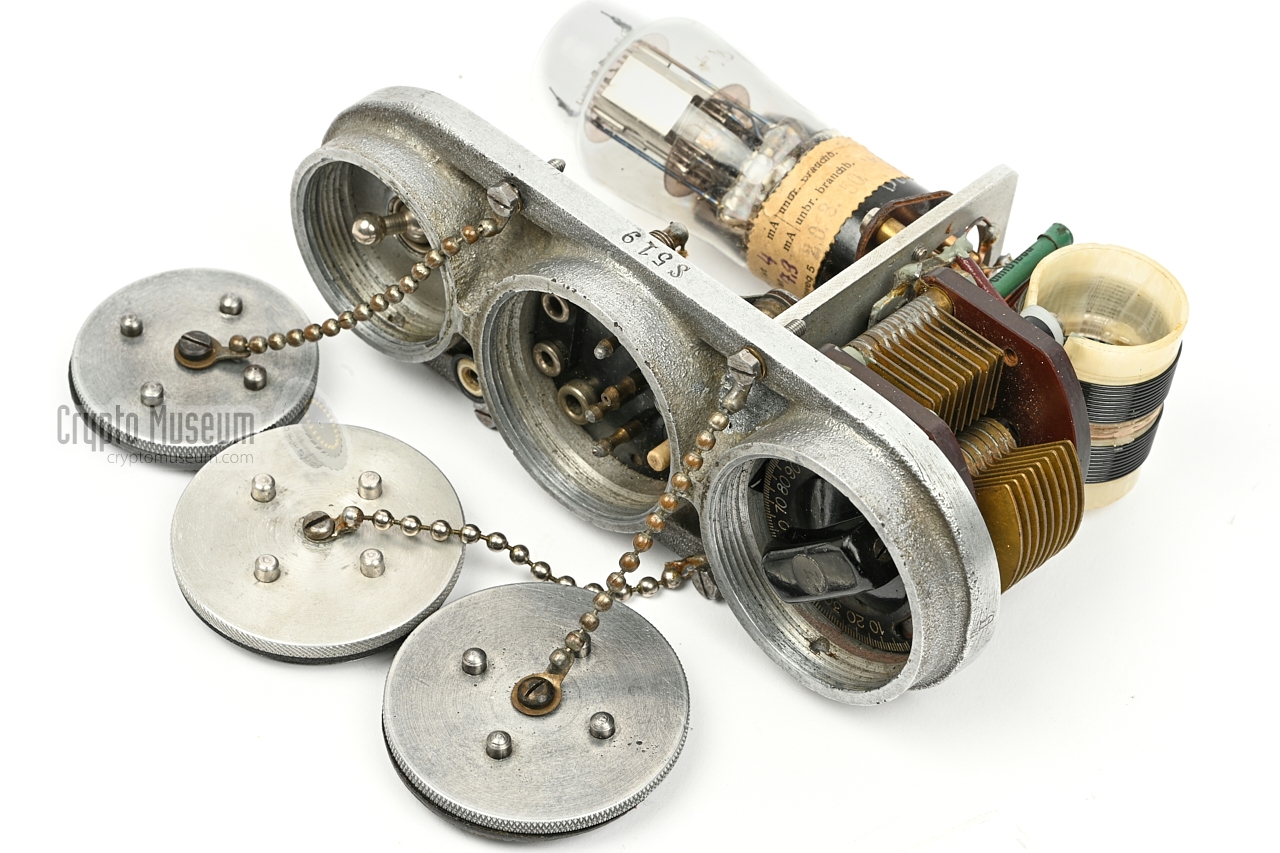
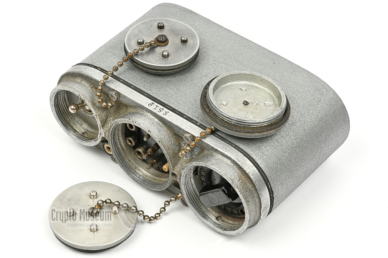
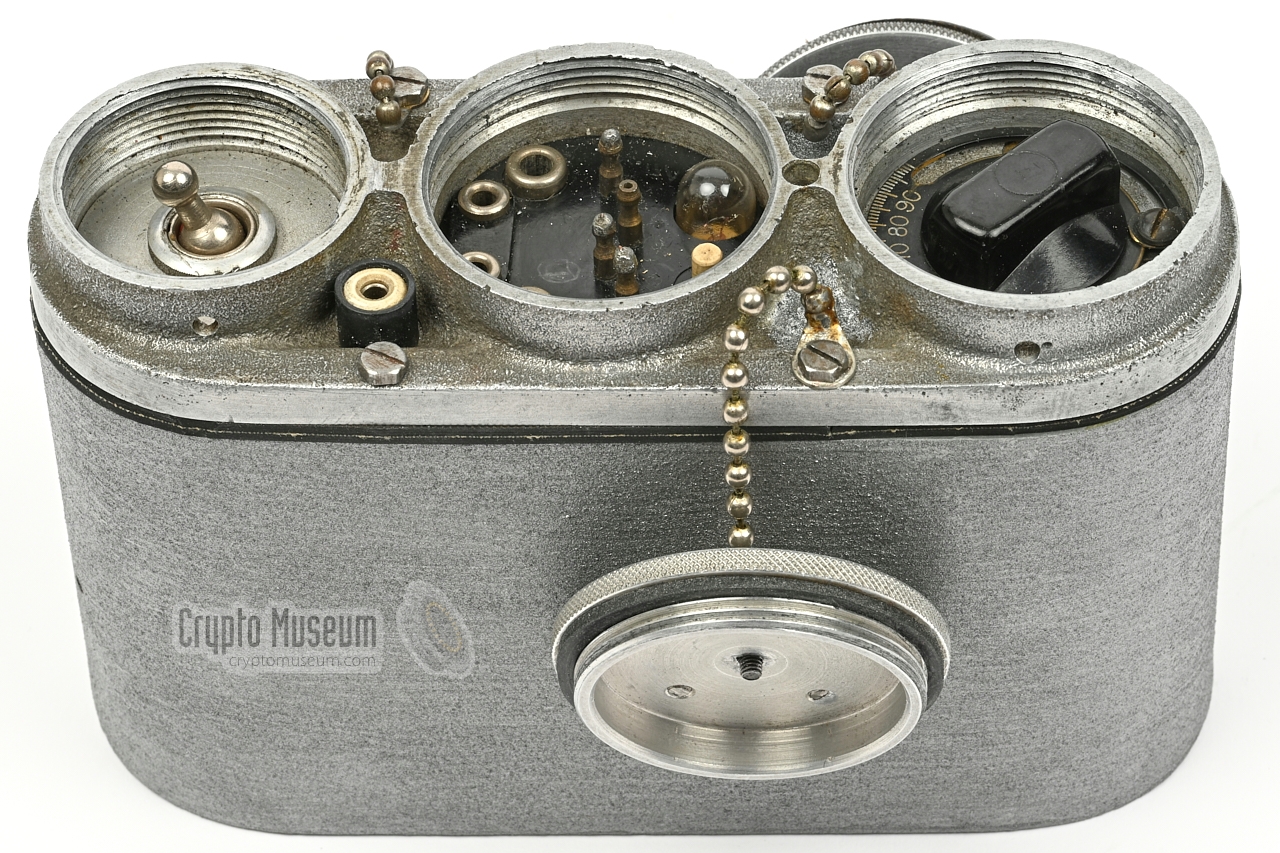
The image below provides a quick overview of the controls and connections
of the Kyynel M-5. The compartment at the centre holds the connections to the
outside world, such as the power supply unit, the morse key and the
antenna wires. It also holds a tuning aid, which consists of a push-button and
a light bulb. When the button is depressed, the bulb acts as a tuning indicator.
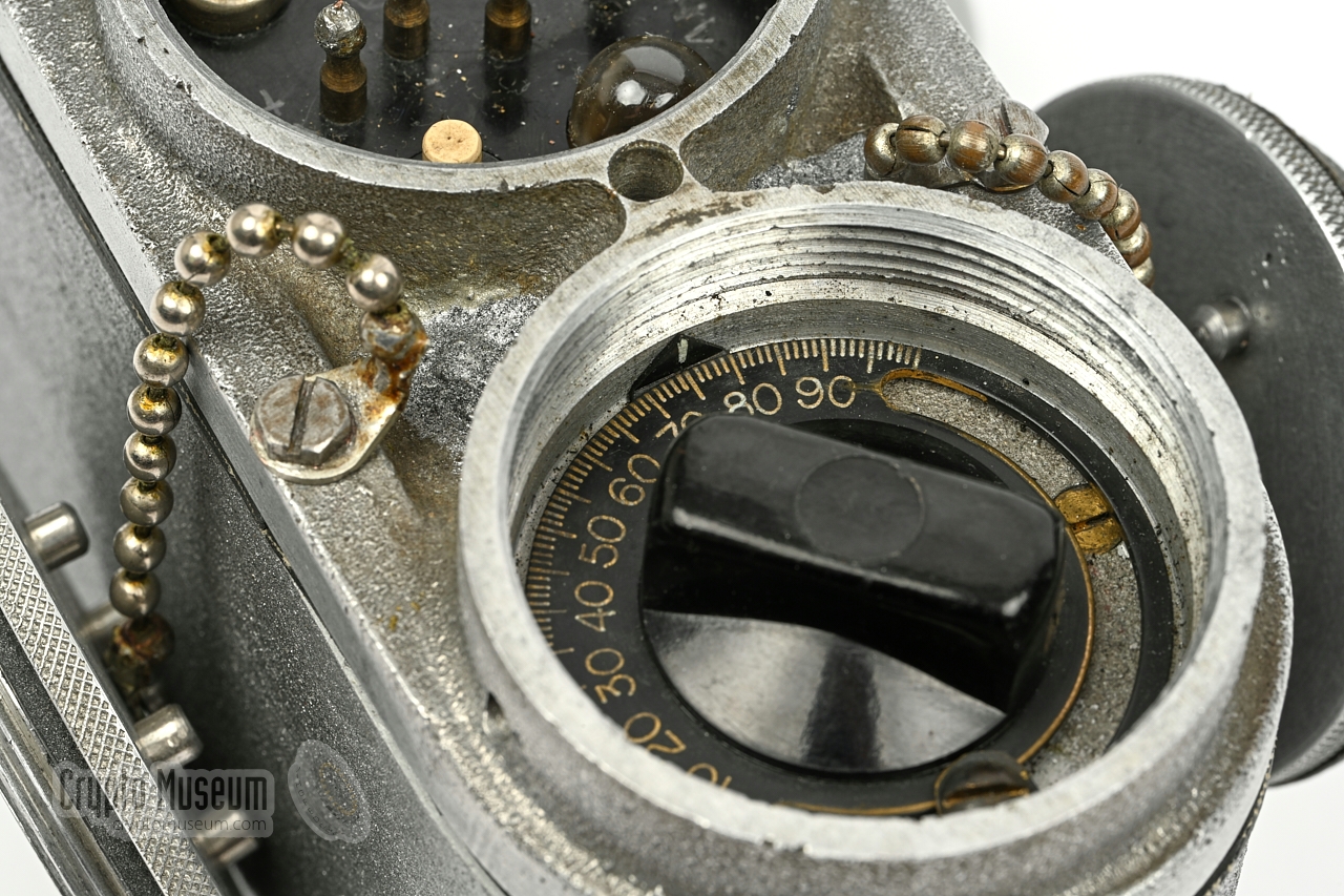
The outer two compartments hold the power switch and the frequency dial
respectively. The linear frequency scale is marked from 0 to 100, which
– on the device shown here – corresponds to a frequency range from
3.38 to 5.53 MHz. With a properly tuned antenna, the device should provide
an output power of approx. 500 mW. The power switch interrupts the 0V rail,
which is the common rail for the 1.5V and 120V power supplies.
The circuit is not connected to the chassis.
|
The Kyynel M5 was supplied with a miniature morse key, such as
the one shown in the image on the right. It has a short cable
that terminates in a bakelite plug with two 3 mm pins.
The morse key should be
connected to the leftmost socket
of the Kynnel M5.
|
|
|
The M5 was powered by external LT and HT batteries that should
be connected to the 4-pin header
in the middle compartment.
The power cable is currently missing.
|
|
|
Two wires of 21 metres each were used as a dipole antenna.
They were supplied on spools and could be configured for various
lengths, depending on the selected wavelength.
The antenna wires are currently missing.
|
|
|
Each Kyynel M5 came with an individual tuning chart that allows
the user to convert the desired frequency or wavelength to the
corresponding value on the
linear schale of the tuning knob.
The chart also specifies the optimum length of the antenna wires
for each frequency range.
An original tuning chart is currently missing.
|
|
|
Below is the circuit diagram of the Kyynel M-5 as it has appeared
in some publications, which is different from the one presented
by Antero Tanninen in [2]. The circuit consists of a DLL21 (V1) double pentode
that is configured as an oscillator. Note that the antenna output is symmetric and that the tuning button (S2) is connected in parallel with the
lamp (La) and not in series as in [2].
Below is the actual circuit as it was taken down by Thomas Höppe (DJ5RE)
in October 2021 from the Kyynel M-5 with serial number S519 [3].
The main difference is that the 0V line is switched (S1)
rather than the +1.5V line. Furthermore, the 0V rail is not connected
to the chassis (ground).
|
| |
Circuit of the Kyynel M-5 with S/N S519
|
In addition, C2 has a value of 200pF (rather than 500pF)
and an extra mica capacitor is connected in parallel to the 200pF
tuning capacitor (C3), probably to alter the frequency range somewhat.
In this configuration, the measured frequency range is from 3.38 MHz
(scale set to 0) to 5.53 MHz (scale set to 100).
Also note the extra antenna socket (Ar)
to which the receiver can be connected. This 3 mm banana socket is located
between the left and middle compartment at the front panel, but was not present
on early devices. Later devices also had a ground socket for the receiver.
|
|
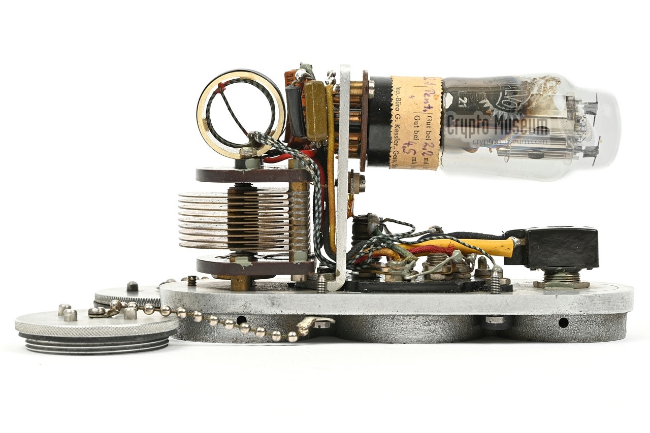
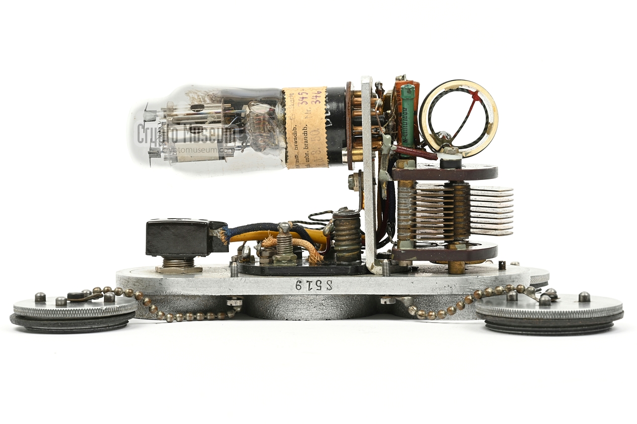
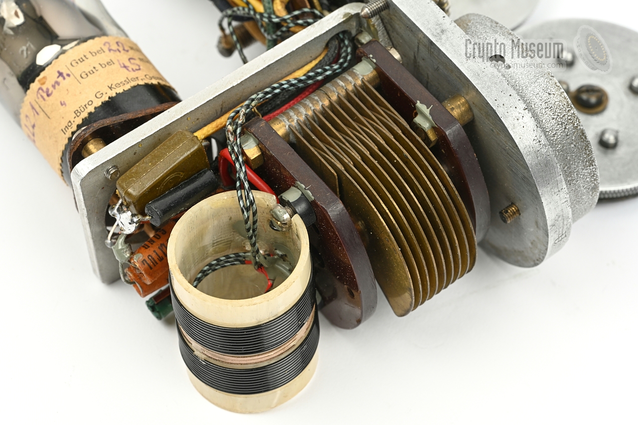
The Kyynel M-5 is housed in a die-cast aluminium enclosure that consists
of two parts: the front panel and a case shell, separated by a rubber
gasket and held together by four screws at the front panel. Three of these
screws also hold the chains to which the watertight caps are mounted.
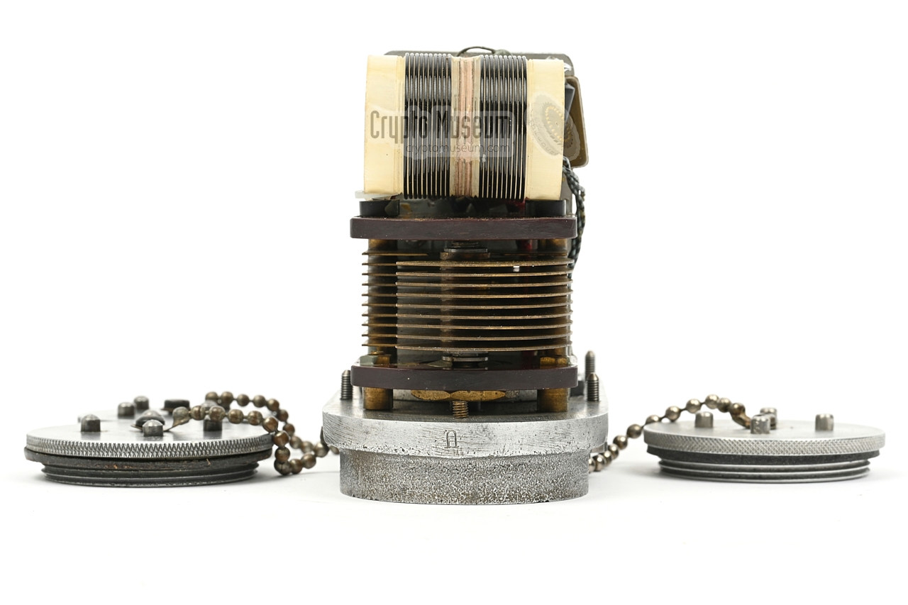
After removing these four screws, the front panel
can be lifted from the case shell. All components are mounted to the front
panel, or to a vertical aluminium panel that is mounted to the front panel.
|
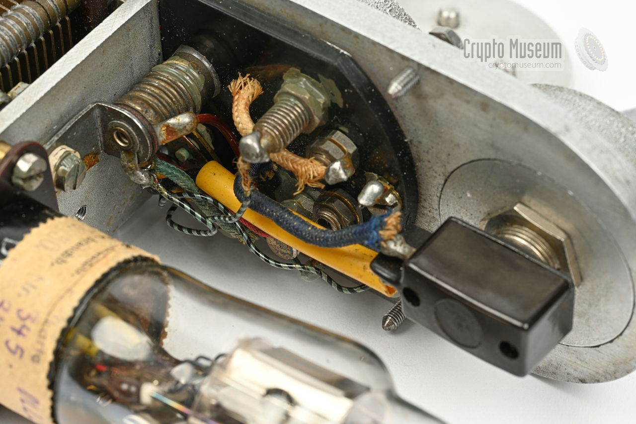
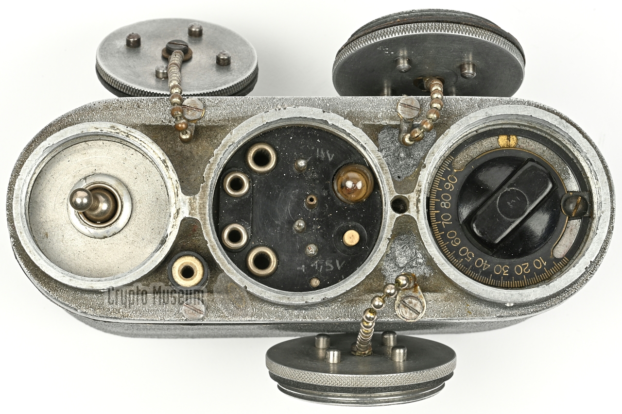
All connections of the transmitter are hidden under the middle cap.
At the the left are two 3 mm sockets for connection of the morse key
and two 4 mm banana sockets for connection of the antenna wires (A1, A2).
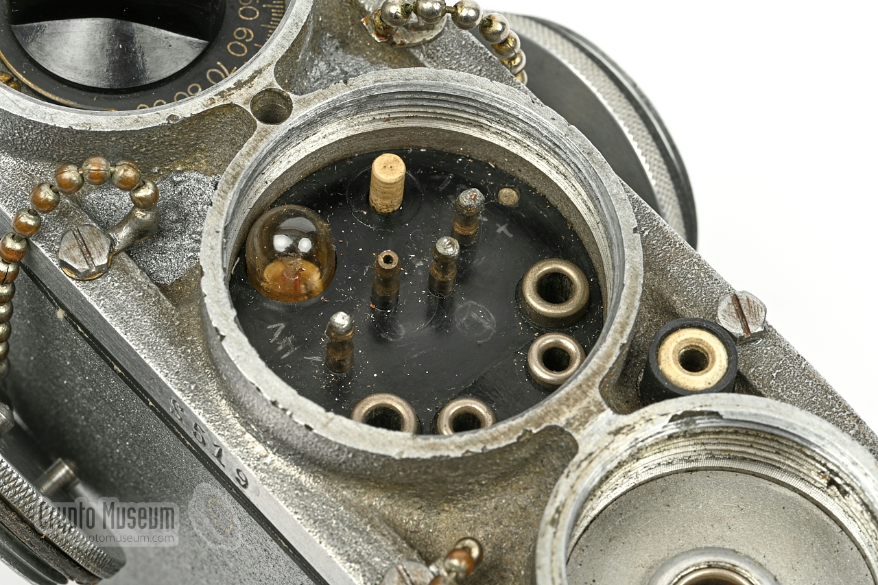
At the centre are four 3 mm contact pins for connection of the (external)
power sources.
The second pin from the top is not used. At the right is the
antenna tuning indicator, which is a regular light bulb.
It is active as long as the tuning push-button is pressed.
At the front edge of the device, between the leftmost two compartments,
is a 3 mm socket for connecting the receiver to the antenna of the transmitter.
On some versions of the device, for example S/N S5100 [1],
an extra 4 mm socket is available for connecting the receiver to ground.
|
Device Clandestine transmitter Model Kyynel M-5 Design Holger Jalander (and other radio amateurs) Manufacturer Finnish Army Depot Company Munkkiniemi Year 1940/41 Purpose Intelligence and guerrilla patrols Type Free-running push-pull oscillator Valve DLL21 Frequency 3.5 - 6 MHz (3.38 - 5.53 MHz) 1 Modulation CW Output 500 mW Power +1.5V (LT), +120V (HT) Current 100 mA (LT), 15 mA (HT) Antenna 2 x 21 m wire (adjustable to 10 lengths) Dimensions 150 x 100 x 56 mm Weight 550 grams
|
-
Measured from the device with serial number S519.
|
|
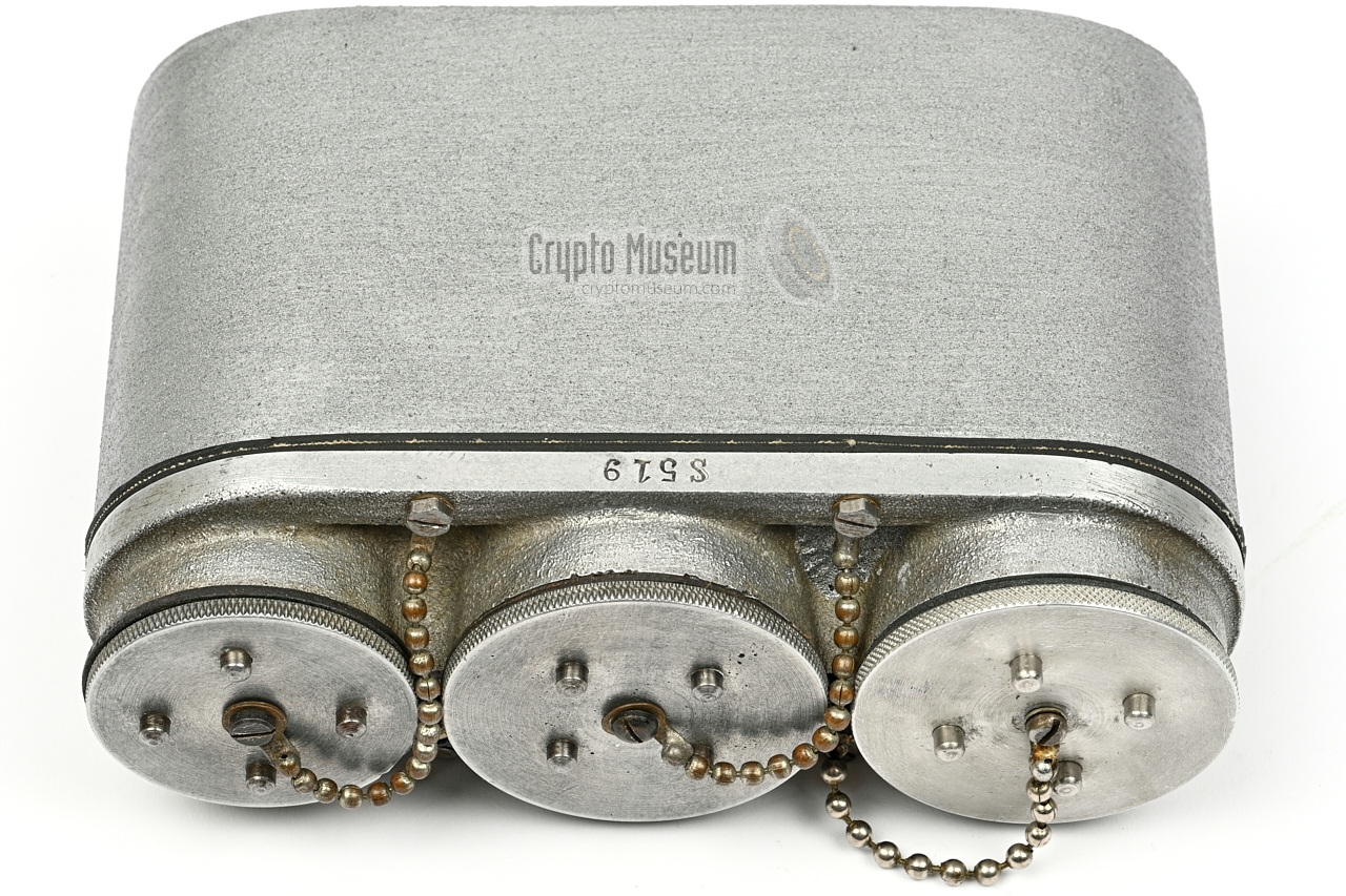
The serial numbers all start with S5, which stands for
Sändaren (transmitter) type 5, followed by a sequential number.
Below is a list of all surviving units that are currently known [4][3].
If we assume that the first one (S/N 0) is a prototype, and that S/N 100
is the highest number found, it seems likely that
around 100 units were manufactured.
The serial number is
engraved in one of the long edges of the front panel
and in most cases also in the aluminium case shell. 1
|
S50 War Museum (Finland) S51 Radio Museum Petäjävesi (Finland) S519 Crypto Museum (Netherlands) S526 Private collector S535 Private collector S536 Private collector S543 Unknown (featured in [1]) S551 Private collector S569 War Museum (Finland) S572 Private collector S575 Private collector S579 War Museum (Finland) S591 Kouvola Military Radio Museum (Finland) S598 Private collector S5100 Private collector (featured in [1])
|
-
Note that the prefix letter 'S' is not always present.
Also note that on some devices the
letter 'U' is imprinted
in one of the short edges of the front panel.
The meaning of the 'U' is currently unknown.
|
- Original morse key
- Tuning chart
- Wire antennas
- Operating instructions
|
|
|
|
Any links shown in red are currently unavailable.
If you like the information on this website, why not make a donation?
© Crypto Museum. Created: Monday 22 June 2020. Last changed: Wednesday, 05 November 2025 - 12:07 CET.
|
 |

|
|
|


![Circuit diagram of the Kyynel M-5 with S/N S519 as taken down by Thomas Höppe [3]](svg/m5_circuit_S519.svg)