|
|
|
|
|

|
|
Finland Sweden Kyynel ← M-10
Like the M-10, the M-11 is largely built with (German) parts from WWII
production, such as the large black
Telefunken metal valves (tubes).
Unlike the M-10 however, the M-11 came in a waterproof metal container,
rather than a cardboard case. It can be operated from within the
container, and all controls and connections are basically identical to
those on the M-10, except for the crystal socket,
which only accepts
smaller crystals with thinner pins.
Such crystals were available in abundance in Europe at the end of
the war, mainly from American military surplus.
|
|
|
|
In addition, the filaments of the valves are series-connected,
and are driven by 3V rather than 1.5V. Furthermore, the two halves
of the double-pentode PA valve (DLL21) are connected in parallel, whereas
in the M-10 they are used in a push-pull configuration.
It is believed that the
first M11 units were manfuactured in low quantities in the early
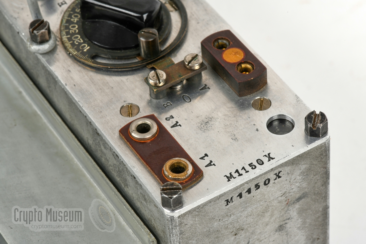
1950's. The M-11X featured here, has
serial number M1150X and was made
in 1955. The radios were in production until at least 1959.
It was the last one made in series production. In total, ~300
units were made [2] 2.
|
-
The receiver has a slightly wider range from 3600 to 4800 kHz.
-
M-10(X) and M-11(X) together.
|
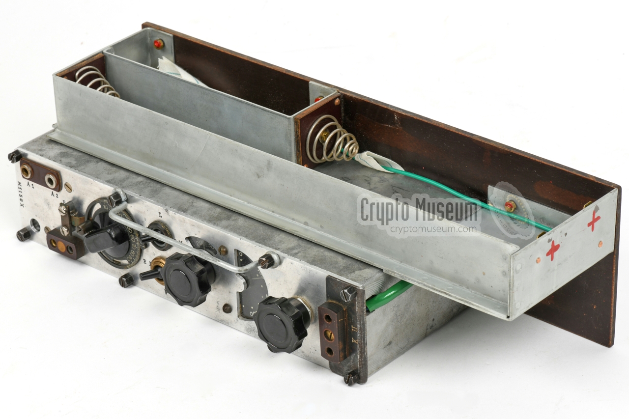
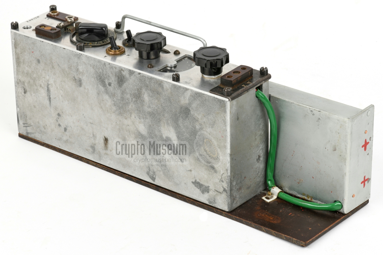
The image below gives an impression of the features of the Kyynel M-11.
The actual transceiver, located at the bottom left, is nearly identical
to its predecessor, the Kyynel M-10, with only minor (internal)
differences.
A rectanglular battery holder is mounted to its top. When the device
it fitted inside the metal container, the batteries are retained by
one of the sides of the container.
A small compartment at the top left, protects the crystal socket,
and provides additional storage space.
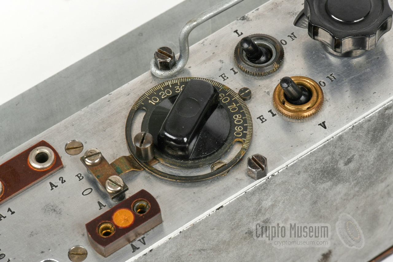
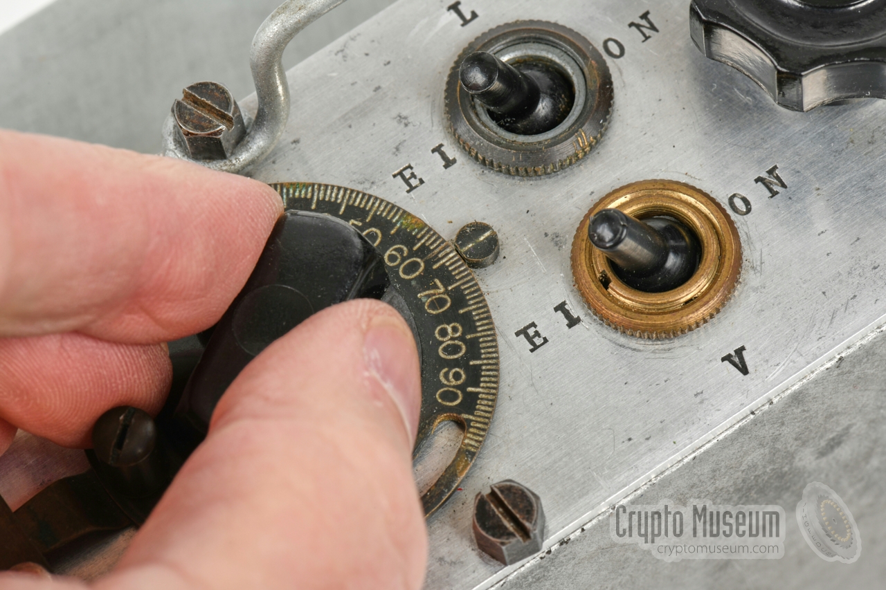
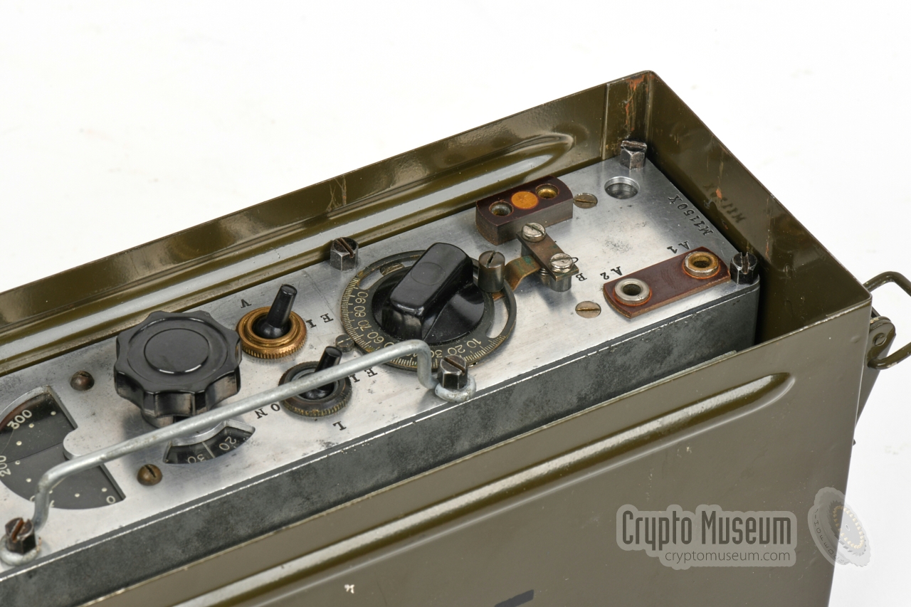
All other connections and controls are at the front panel. At the top left
is the antenna socket
– marked A1/A2 – to which the wire antenna (dipole)
should be connected. At the bottom left is the
socket for the morse key, marked AV.
At the far right is the
socket for the headphones (KU).
|
- VRHAG — M-10
Initial version, first made in 1942, based on the M5 transmitter and
M7 receiver. Supplied in a cardboard container. 25 units were
sold to Sweden during the war. Also known as VRHAG and as P-12-24.
- VRHAG — M-10X
Crystal version of the M-10, first made in 1944. Towards the end of the
war, some M-10X units were manufactured in Sweden, after the workshop had
been relocated. The serial numbers of the sets that were made in Sweden
have the suffix 'B'. They were also known by their Swedish designator
1 W Br m/44.
- VRHAI — M-11
Post-war version of the M-10, first made in the early 1950s. Housed in a metal
container and uses 3V for the filaments of the valves, rather than 1.5V
(filaments in series). Also known as VRHAI.
- VRHAI — M-11X
Post-war version of the M-10X, first made around 1955. Suitable for the smaller
CR-5/U crystals that were available from American military surplus after the
war. Not suitable for M-10X crystals.
The set featured here is of this type.
It has serial number M1150X.
|
|
|
Differences with the M-10
|
|
|
- Metal storage container 1
- Different crystal socket
- Filament wiring (2 x 1.5V battery in series with centre contact)
- PA valve (double pentode) in parallel rather than in push-pull (also in M-10X)
- Receiver reaction control by means of variable capacitor rather than potentiometer
- Different battery compartment
|
-
Initially, the M-11 was supplied in a cardbox suitcase, similar to the one
that was provided with the M-10. The metal container was probably issued
in the mid-1950s.
|
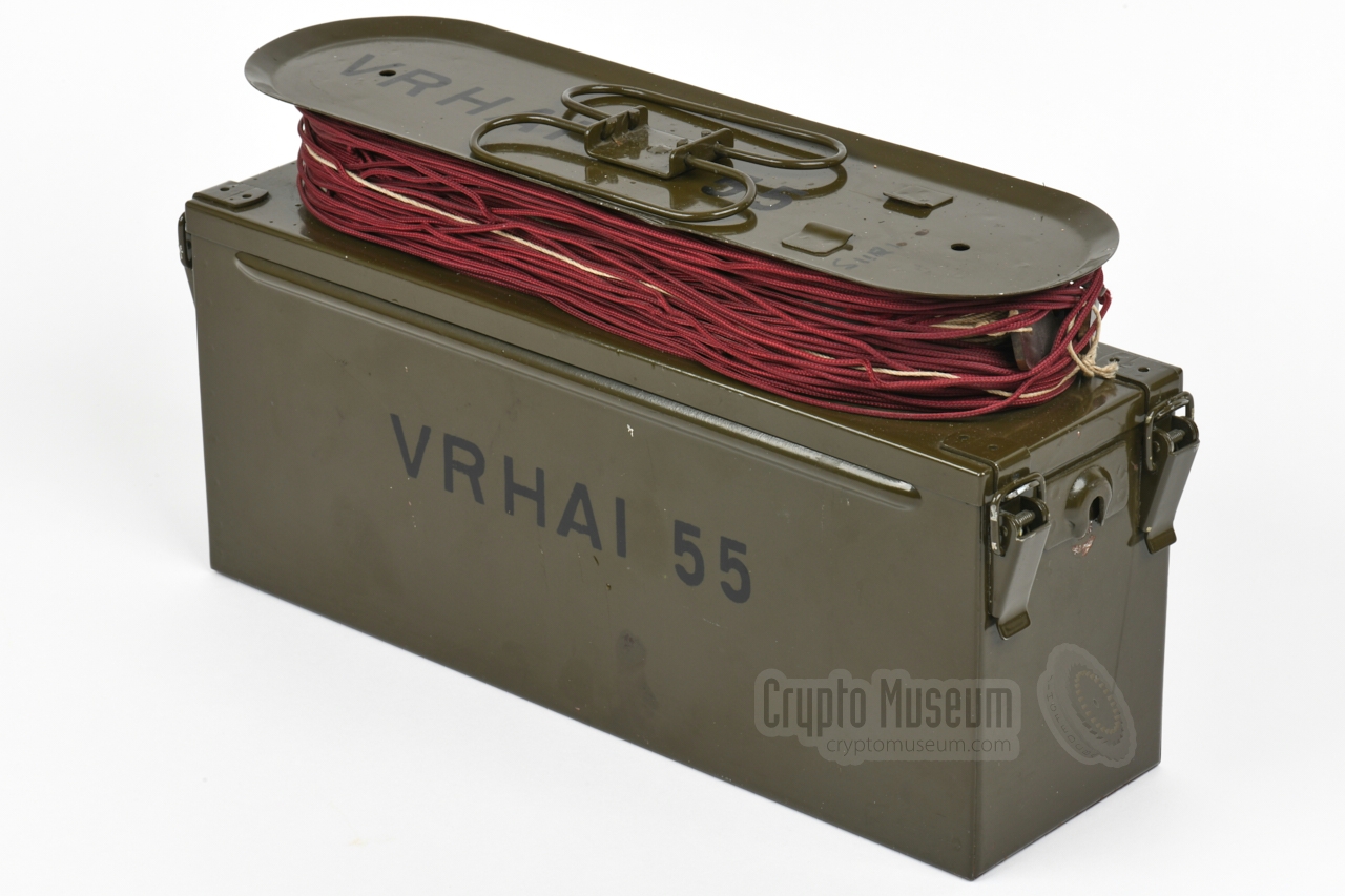
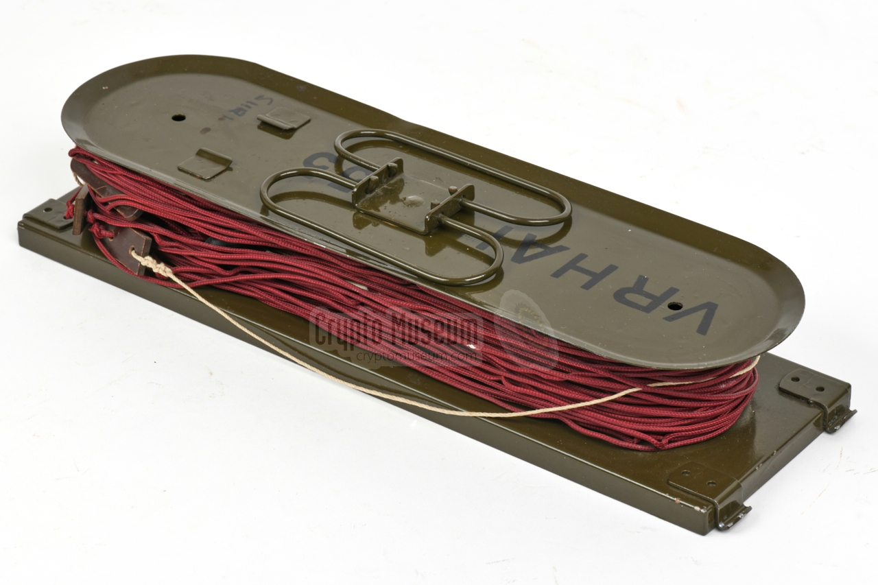
The M-11 was supplied in the waterproof green metal storage
container show in the image on the right. It measures 340 x 180 x 97 mm
and weighs approx. 5.6 kg, batteries not included.
A canvas strap can be attached to the sides,
so that it can be converted into a carrying case.
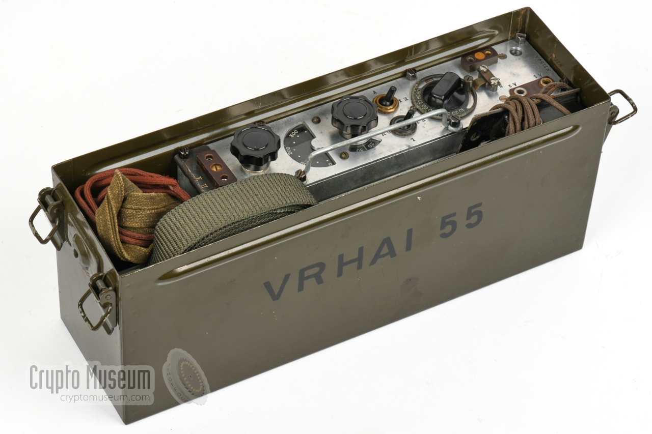
The device can be operated from within the container.
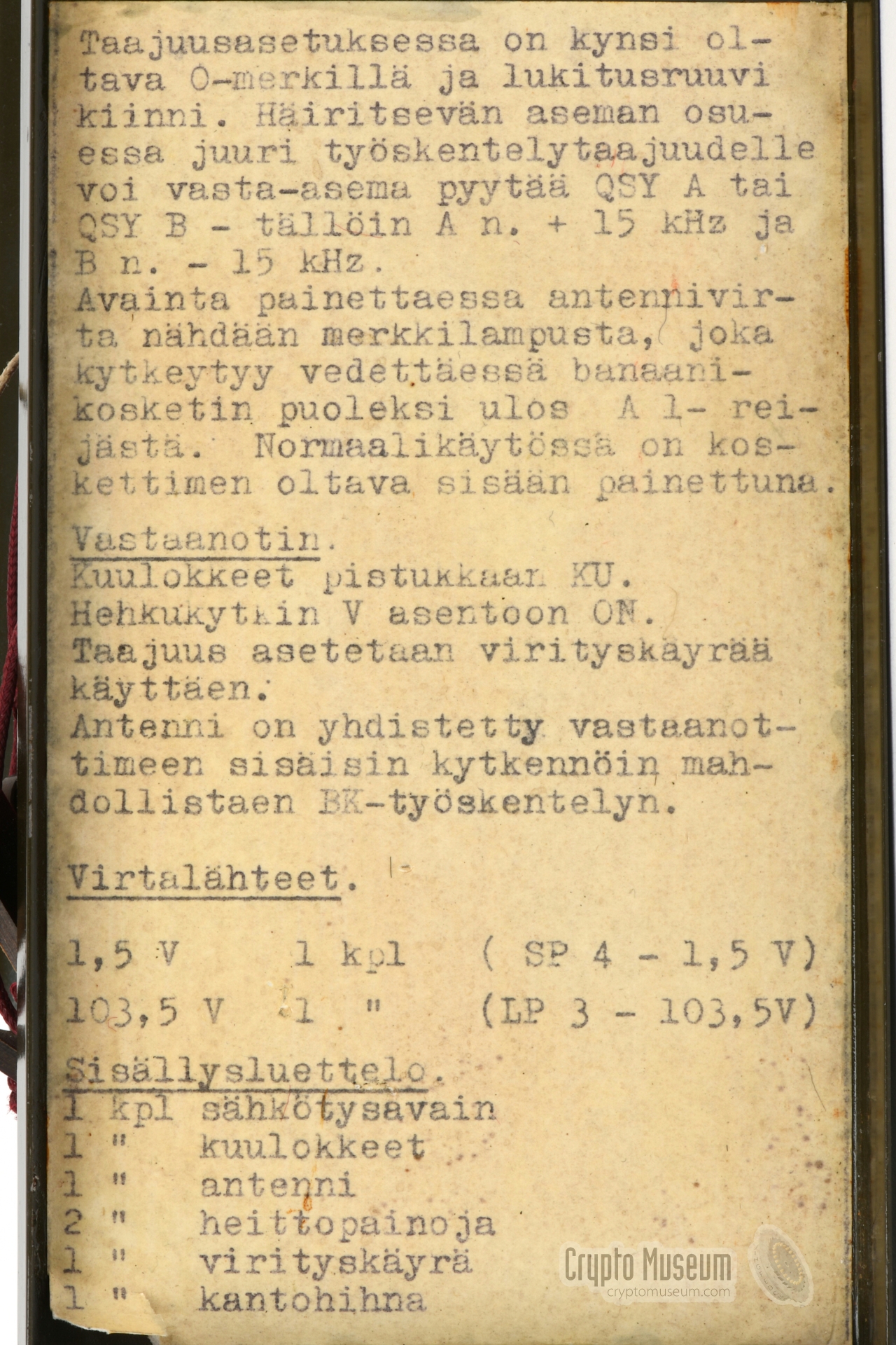
The case is closed at the top with a removable waterproof lid, that
also acts as a spool for the antenna wires and ropes. Inside the lid
are two pages with operating instructions.
➤ Instructions page 1
➤ Instructions page 2
|
|
|
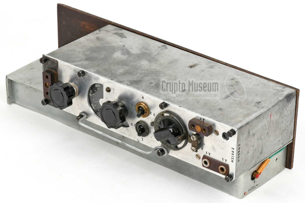
The actual M-11 radio set is visible in the image on the right.
It is mounted onto a thick brown pertinax base plate, and has an
open battery compartment mounted at its top. The (green) wiring
to the batteries is fixed (not removable).
The radio needs two voltages for its operation: 120V DC for the
anodes of the valves (HT), and 3V for their filaments (LT).
Note that the crystal should be
inserted at the side of the device,
in the small compartment that is visible at the top.
|
|
|
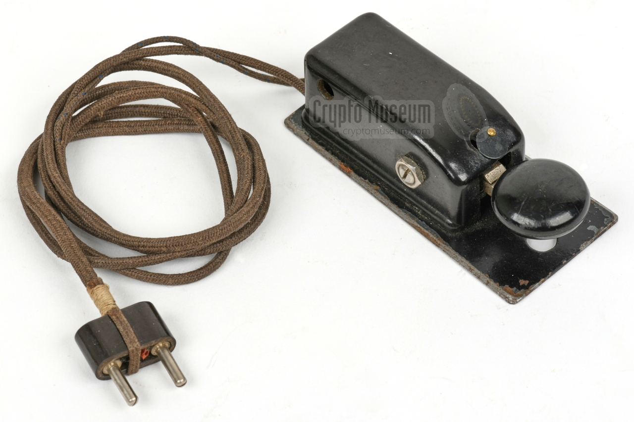
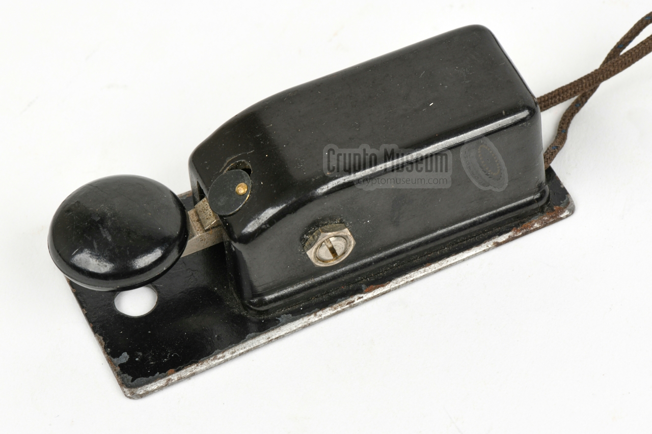
The Kyynel M-11 was supplied with the same miniature morse key as
the M-10. It has a tapered bottom panel that can be
fitted to the two rails
on the top lid of the metal container, so that it
can be operated more easily.
The morse key can be connected to the
socket at the lower edge
of the front panel. When unused, it can be stowed inside the metal
container.
The key is connected in series with the anode of the
DLL 21 transmitter valve and directly switches the 120V supply
to the transmitter on and off.
|
|
|
The Kyynel M-11X was supplied with a pair of 600 ohm high-impedance
speakers, mounted to a canvas strap that allows them to be worn on
the head. The headphones are connected to the
2-pin socket at the right
of the front panel.
The image on the right shows the original headphones that were supplied
with the Kyynel M-11X featured on this page.
|
|
|
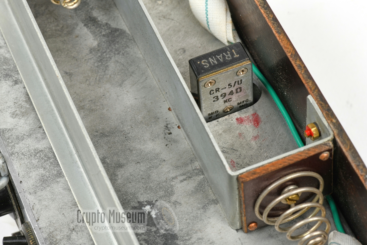
The M-11 has been adapted for smaller crystals with thinner pins,
such as the CR-5/U shown in the image on the right. Such crystals
were widely available after WWII had ended, mainly from American
military surplus that had been left behind in Europe.
Note that the crystal sockets are not suitable for the
larger crystals (with thicker pins)
that were used with the wartime M-10.
|
|
|
Each M-11 came with an individual tuning chart that shows the
tuning details of the device. In particular it shows the settings
of the antenna matcher knob for each frequency.
The double-sided printed chart measures 75 x 106 mm and comes
in a plastic sleeve. The curve is hand-drawn.
➤ Hi-res scan of the tuning card
|
|
|
The antenna basically consists of two wires of 20 metres each. Depending on
the frequency in use, the wires can be adjusted at 4 different lengths.
When not in use, the wires are stored on the oval spool that is part of the
top lid of the container.
The instructions – at the inside of the lid –
show how to setup and use the antenna. With aid of a separate
rope and two throwing weights, the
wires are effectively used as a dipole.
|
|
|
These two throwing weights were supplied with the set, and were usually
stowed in the storage compartment of the metal container.
They can be
attached at the end of the two ropes that are stowed on the oval spool
on the top lid of the metal container,
and can be used to mount the antenna wires between two trees.
|
|
|
|
The M-11 is housed in the same die-cast aluminium enclosure as the M-10,
developed during WWII by Finnish reserve-captain Holger Jalander.
The interior is mounted to the rear of the front panel, and can be accessed
by releasing the eight black hex-bolts at the edges of the front panel.
|
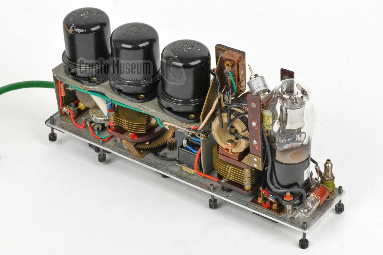
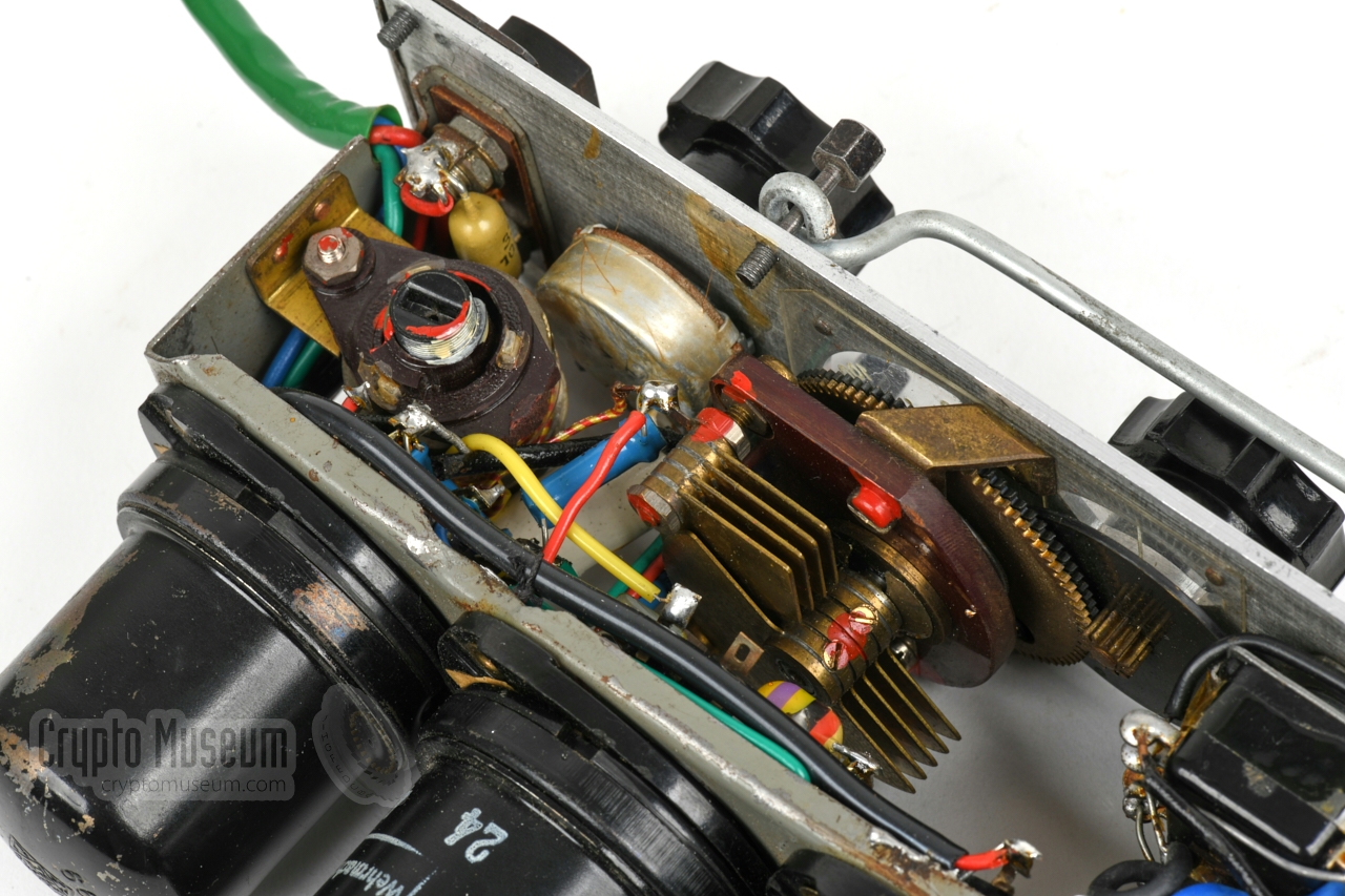
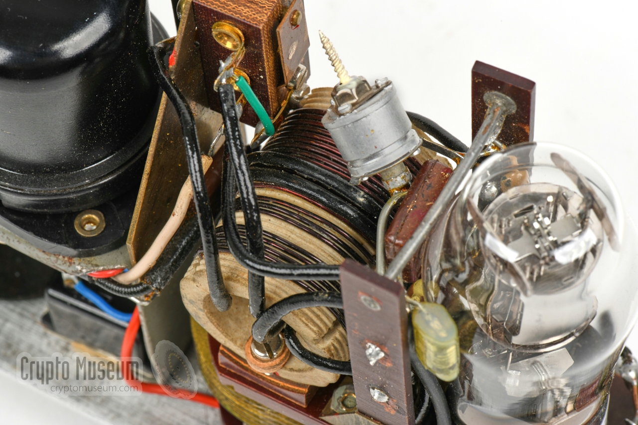
The image on the right shows the interior of the M-11
in front of the die-cast enclosure, with the front panel facing down.
At the far right are the three German black metal valves of the
receiver – DF11 and DDD11 – mounted on a sub-chassis.
At the front left is the DLL21 transmitter valve — a dual pentode —
with the tuned circuit directly behind it. A similar valve was used in
the WWII German Abwehr
radio set SE-109/3, albeit in a small
form factor (DLL22T).
As this is the crystal version, an crystal socket is mounted between the
tuned circuit coil and the first receiver valve.
|
|
|
|
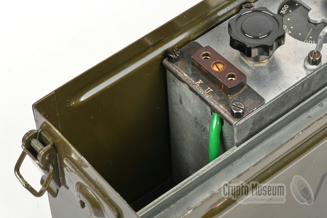
The set is powered by two voltages — 120V (HT) and 3V (LT) — for which an
improvised battery compartment is bolted to the side of the device.
A small section of the
battery compartment is shielded-off to accomodate the crystal socket,
which is also at the side of the radio. It allows the crystal to remain permanently installed, whilst the
radio is stowed inside the metal container.
|
Below is the circuit diagram of the transmitter, which is built
around a DLL21 double-pentode, of which the two halves are connected
in parallel. At the top is the tuned circuit, which consists of a large
coil (L1), a variable 140p capacitor and several fixed ones. Note that
the two capacitors that are shown in grey, were added later – probably
in the late 1950s – to adapt it for amateur use [1].
At the top right are the antenna sockets (A1/A2). In receive mode, A2 is
connected to ground. When the antenna is inserted half-way into socket A1,
the lamp can be used as a tuning indicator. When the plug is fully inserted,
the lamp is shorted. Switch S1(A/B) is shown in receive mode.
Note that the two filaments of the DLL21 are each powered by a separate 1.5V
telephone battery, with the common contact connected to ground. For this reason,
the filament voltage is specified at 3V. Also note that the +120V anode voltage
(HT) is switched directly by the morse key, which should be connected at the
bottom left. The transmitter can be used in free-running mode, in which case
L3 and L4 are used as a feedback loop, which is connected to g1/1 and g1/2.
When inserting a crystal into the socket,
switch S3 is engaged, which replaces L4 by the crystal.
The diagram above shows the circuit diagram of the receiver, which is built
around two DF11 valves and one DDD11. The first DF11 is used as an aperiodic
RF amplifier. At the center is the second DF11, which is used as a regenerator
and detector.The circuit is very similar to that of
the M-10,
but uses a variable capacitor (C2) for controlling the reaction,
rather than a potentiometer.
At the far right is the audio (AF) amplifier stage, which is built around
a DDD11 double-triode.
|
- Exterior cleaned
- DLL21 valve mounting posts fixated
|
The DLL21 is a double pentode that is the only valve (tube) that is used in
the transmitter.
It is similar to the DLL22T that was used in the
German SE-109/3 spy radio set
of the era, albeit in a larger enclosure and easier to obtain.
In the M-10 the two halves of this valve are used in a push-pull configuration,
but in the M-11 they are simply connected in parallel (just like in the M-10X).
|
The DF11 is a black metal valve (Stahlröhre), first made in 1940 by
Telefunken, of which two are used here.
It is a directly heated Penthode that
is suitable for RF, IF and AF applications.
It has an LT voltage of 1.2V and a typical Anode voltage of 90V.
Below is the pinout of the DF11.
Note that the unused terminals (marked n.c.),
may be used as a mounting hub for other components.
➤ DF11 datasheet
|
DDD11 was a metal double-triode valve (German: Stahlröhre),
first made in 1940 by Telefunken.
It was used during and after WWII, typically in the AF section of
a receiver.
➤ DDD11 datasheet
|
TX frequency range 3800 - 4800 kHz (79 - 63 m) RX frequency range 3600 - 4800 kHz (scale 1-300) 1 HT voltage 120 V DC LT votlage 3V RX anode current 7 mA TX anode current 28 mA Filament current 100 mA TX power output 0.5 - 1 W Weight 5.6 kg Range 100 - 200 km
|
All Kyynel radio sets have their
serial number engraved in the front panel,
and commonly also in one of the sides. The diagram below shows how the
serial number is constructed. It consists of a model number, a serial
number and (optionally) one or more suffixes.
|
M11 50 X 1955 Crypto Museum M11 71 X 1959 Antero Tanninen
|
|
|
|
Any links shown in red are currently unavailable.
If you like the information on this website, why not make a donation?
© Crypto Museum. Created: Sunday 07 June 2020. Last changed: Wednesday, 05 November 2025 - 12:07 CET.
|
 |

|
|
|


