|
|
|
|
|

|
|
Cold War DDR Stasi
The set consists of a transmitter
– suitable for frequencies between 3.15 and 8.5 MHz – a
mains power supply unit, a high-speed keyer, a
burst encoder
and several accessories and spares.
The set does not contain an HF receiver, as it was assumed that the
agent already had one. In the early 1960s, a short-wave capable receiver,
such as the Grundig Luxus Boy 200 E,
could easily be purchased in a local store without attracting attention.
The agent used the receiver for receiving instructions via the
One-Way Voice Link (OWVL),
also known as a Numbers Station.
|
|
|
|
Communication from the agent to the DDR spy base,
was usually done via dead drops.
The transmitter would only be used in case of an emergency, for
example when the dead drop area was
compromised. To avoid discovery – for
example during a house search – it was usually hidden in a predetermined
underground hiding place, known as a cache.
The agent had coded instructions (printed with invisible ink)
on where to find the cache. He also
had printed instructions on how to use the set, and had several
One-Time Figure Pads (OTFP)
for the encryption of the messages.
|
Using a clandestine transmitter from within the host country, is not
without risk. If the enemy is able to intercept the transmission, it might be
possible to determine the transmitter's location by means of
radio direction finding (RDF), which could potentially lead
to the arrest of the agent.
For this reason, a so-called burst encoder
was included in the set. It allows a coded message to be stored as
morse code numbers
on a piece of regular audio tape by means of a puncher.
Once the message is complete, it can be played back at high speed
with a manually operated keyer.
|
|
|
|
In the past, transmitters of this type
have reportedly been found by the
Bundeskriminalamt (BKA)
and by the Bundesamt für Verfassungsschutz (BfV)
in forgotten caches throughout Germany [4].
They have also been found in Austria and Switzerland, and perhaps in
other countries as well [2].
The one shown here, was found in 2018 in a
forgotten cache in a West European country.
Based on the manufacturing codes on some of the components,
it was probably manufactured in 1962.
|
-
The official name of this radio is currently unknown, which is why we use
the nickname 'DDR Type 2' as coined by Louis Meulstee in 2004 [2].
-
OTS = Operative Technische Sektor (Operational Technical Division).
|
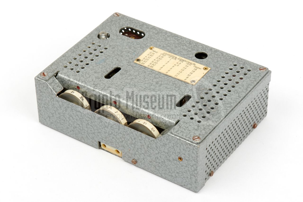
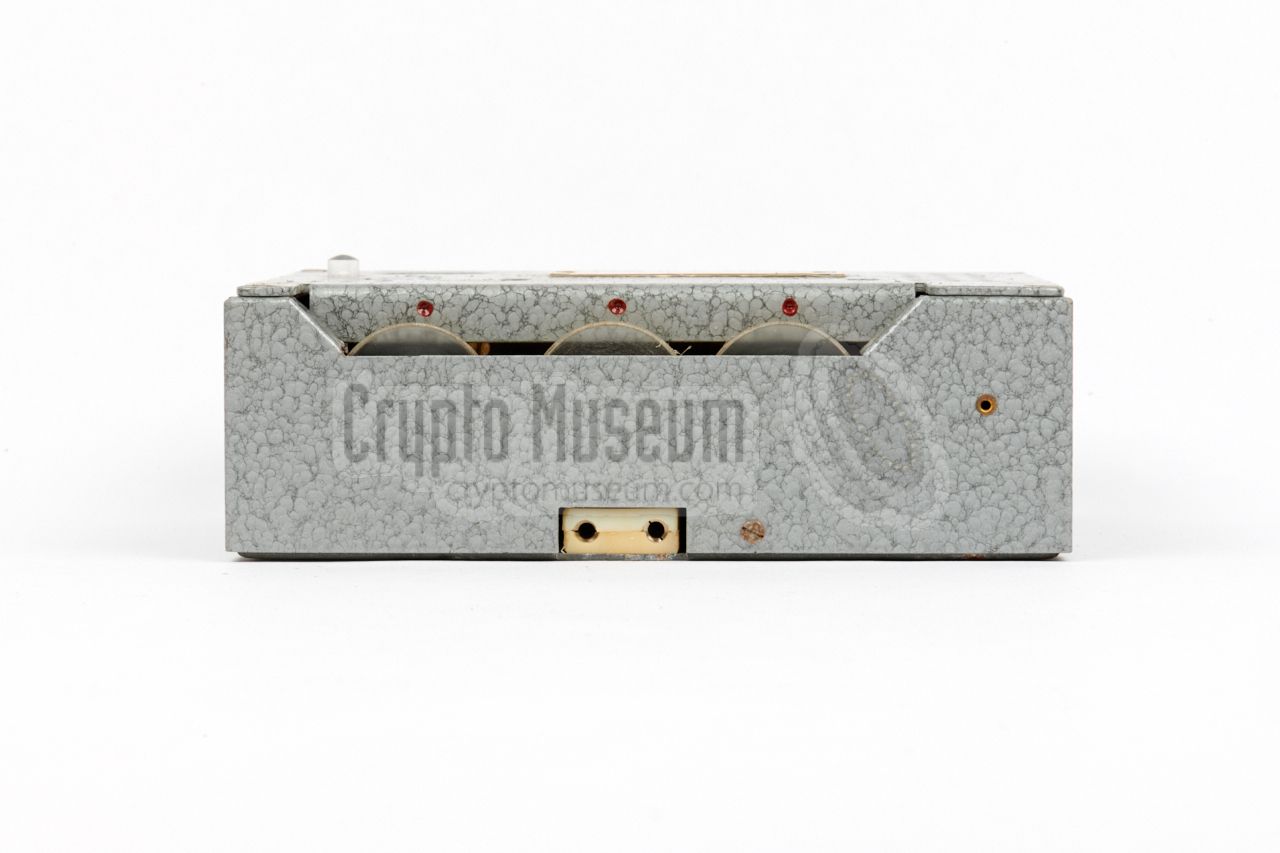
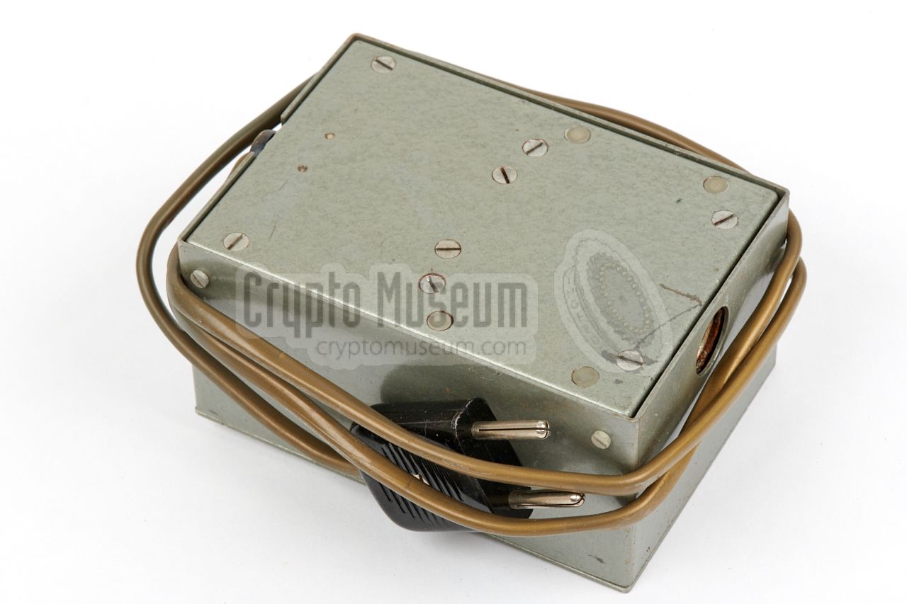
The transmitter measures 150 x 105 x 50 mm and is housed in a grey hammer paint metal enclosure.
The diagram below gives an overview of the controls and connections on the
body of the device. At the left is a 5-pin 240° DIN socket
for connection to the PSU (which has an identical socket).
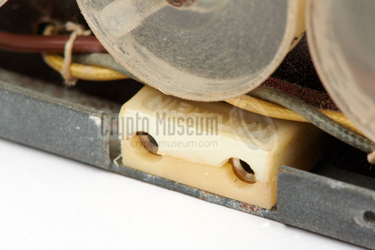
At the front bottom is a 2-pin Kathrein socket
for connection of the manually operated burst keyer.
The transmitter has four controls:
three recessed knobs for adjusting the
frequency, and a push-button
at the top left. The latter is used to enable
the transmitter whilst tuning the oscillator and PA circuits.
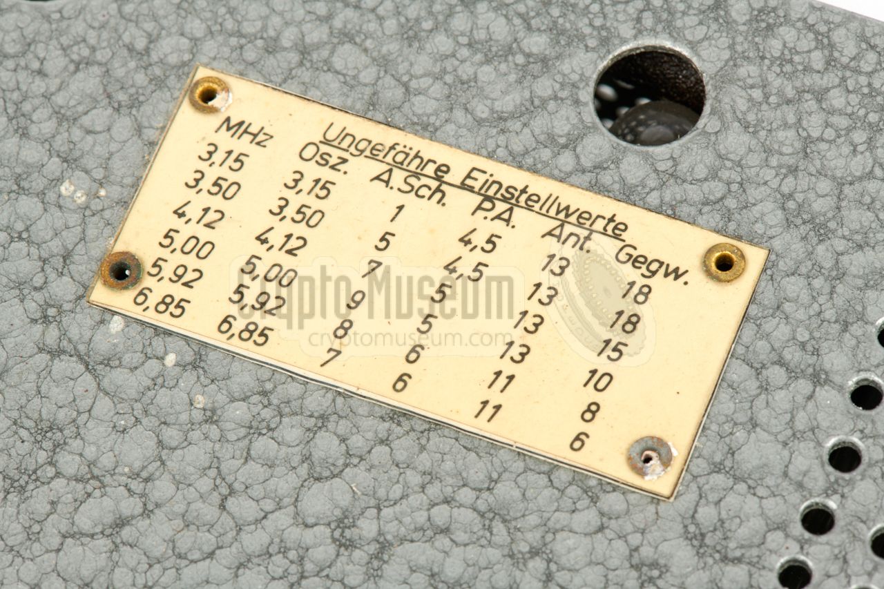
The tuning table
on the top surface gives a rough pre-set for each frequency. It also specifies
which taps on the wire antenna
and the counterpoise should be selected for each band.
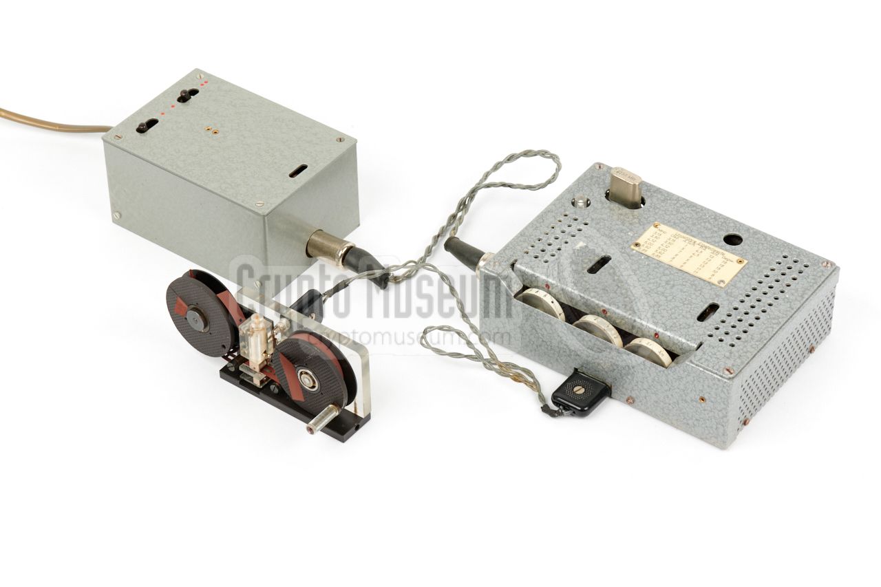
The image above shows a typical setup for sending a message. At the
right is the transmitter,
which is powered from the 220V AC mains via the
power supply unit (PSU) at the left.
A crystal for the desired frequency is
installed in the crystal socket
at the top left of the transmitter and the tuning knobs
have been set to the values given in the table. Antenna and counterpoise
wires are connected at the rear (not shown here).
At the front is the manually operated tape-based keyer.
The PSU has two switches: one for enabling the HT voltage, and one for
selecting the desired HT voltage and, hence, the RF power output — 10 or 20W.
The 6.3V AC LT voltage is always present.
In order to send a message, the clear text is first translated into numbers
using some kind of conversion scheme. It is then encrypted by means of the
so-called One-Time Pad (OTP),
also known as a One-Time Figure Pad (OTFP).
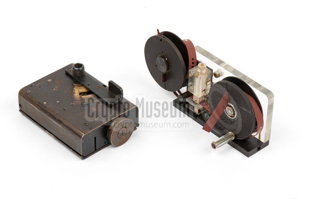
The hand-puncher
is then used to record the numbers onto a regular ¼"
magnetic (audio) tape, by punching them out
as morse code characters.
Once the message is complete, the tape is installed on the keyer
and played back at very high speed.
|
The transmitter is the heart of the clandestine radio station. It is
suitable for the 3.15 to 8.5 MHz frequency range, and delivers an output
power of approx. 20 Watts in CW (morse).
It is crystal operated and has a socket for a HC-6U format
crystal at the top left. Suitable crystals
were supplied with the set.
For each frequency, the three knobs at the front should be adjusted,
using the table at the top as a guide. Indicator lamps are present to
find the optimal settings.
|
|
|
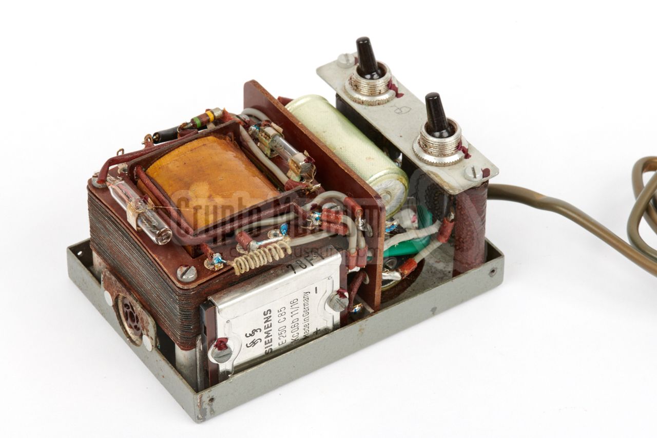
The PSU shown on the right provides the LT and
HT voltages for the transmitter. It is suitable for the 220V AC mains only,
which implies that the set was intended for use in Western Europe, e.g. in
West-Germany, Austria, Switzerland, etc..
As soon as the PSU is plugged into the mains, it provides the 6.3V LT
voltage for the filaments of the valves. The first switch
( ● ) enables the HT voltage, whilst the second one
( ● |
●● )
selects between +235V and +415V, which corresponds to an RF output power
of 10 or 20W respectively.
|
|
|
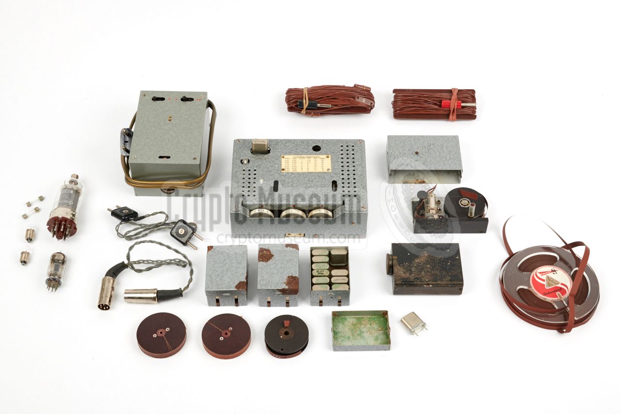
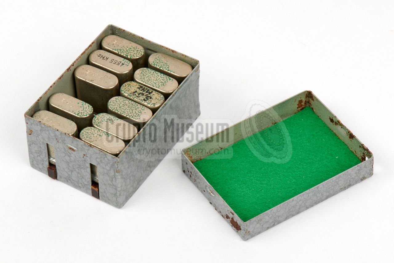
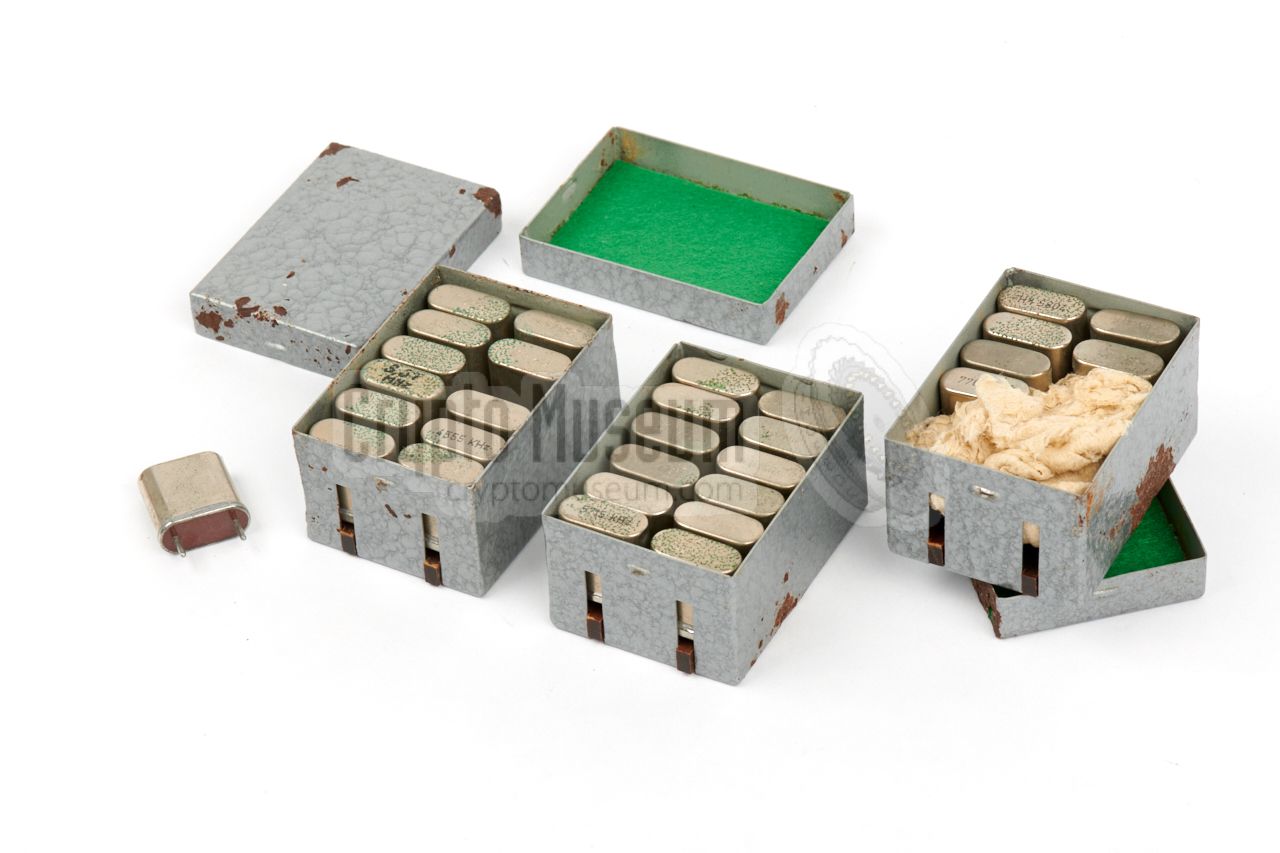
The transmitter came with 30 quarz crystals, spread over three metal
storage boxes that were basically copies of the crystal boxes supplied with
West-German spy radio sets like the SP-15.
The first two boxes contain 24 crystals for the 3.15 to 7 MHz frequency
range, but the third box contains 6 crystals from 7.087 to 8.370 MHz,
which is above the specified range.
➤ List of frequencies
|
|
|
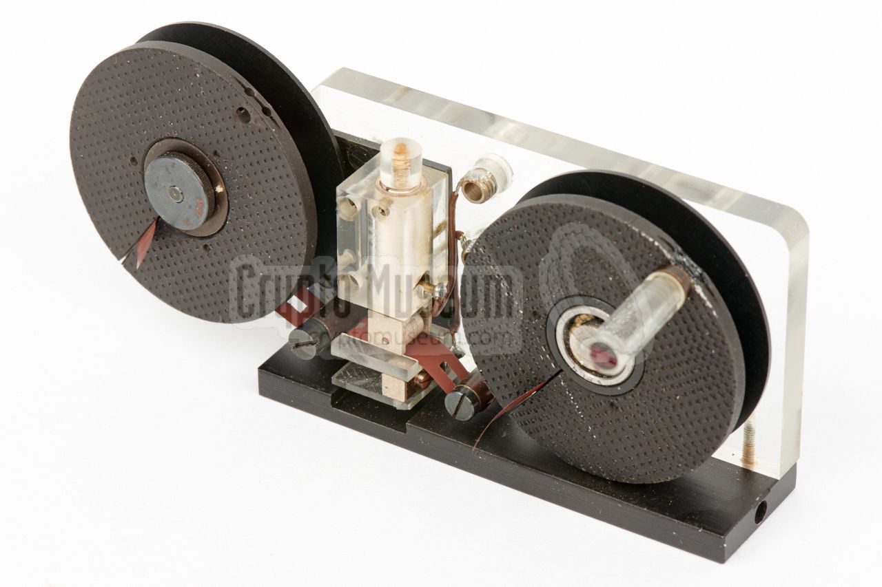
Messages are first converted from letters to numbers, and then encrypted
by means of a One-Time Pad (OTP).
The encrypted message is then stored onto
a regular piece of ¼" audio tape, by means of the puncher shown here.
The knob on the left is used to select a number (0-9) after which a
lever at the back is pressed.
The number is then punched into the tape as a series
of holes that represent the morse code
of the number. E.g. '4' is punched as
➤ More information
|
|
|
Once the message is complete, the tape is wound onto an empty reel
that is installed on the left arm of the keyer shown on the right.
The lever is then used to wind the tape from the leftmost reel to the
pickup reel at the right, whilst the holes in the tape are read by
a switch at the bottom. As this switch is connected to the key
input of the transmitter, the numbers on the tape will be transmitted
in morse code.
➤ More information
|
|
|
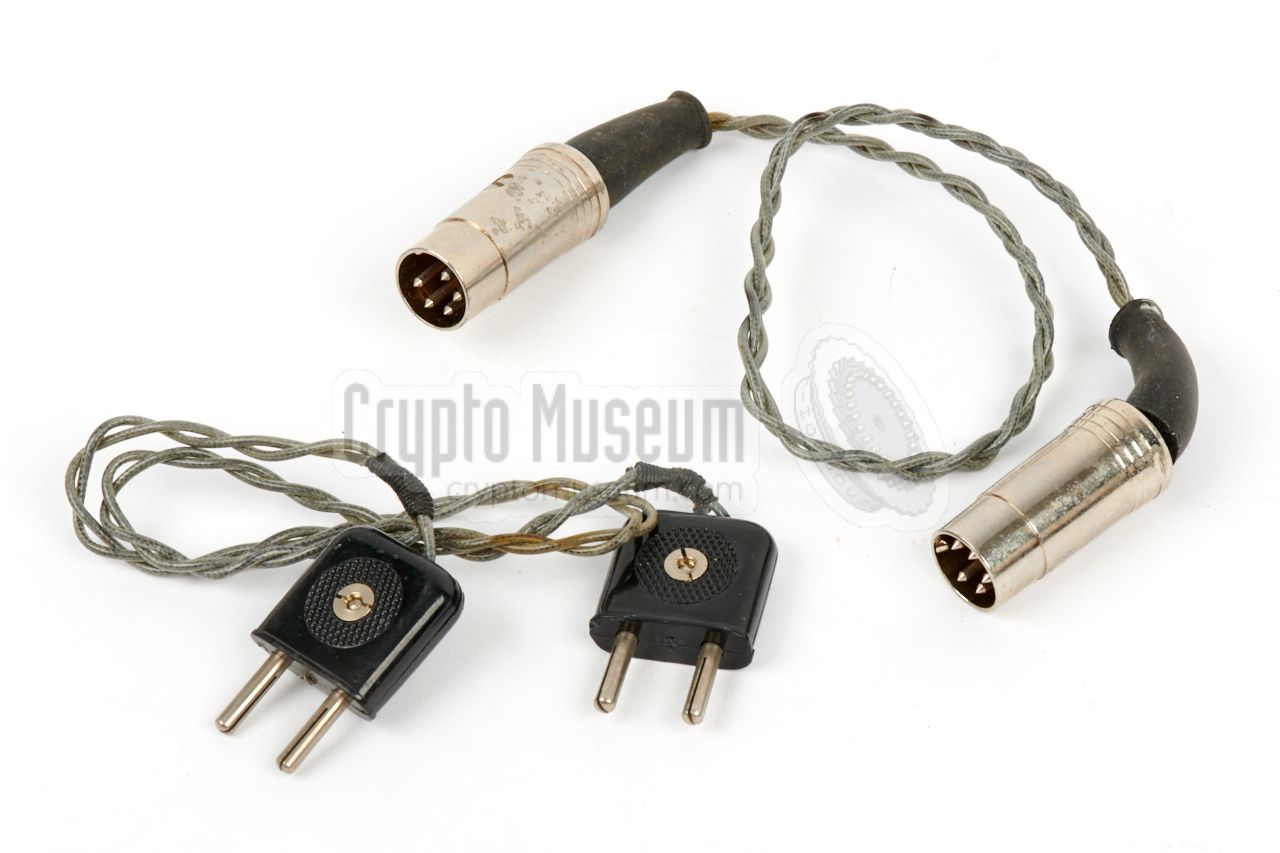
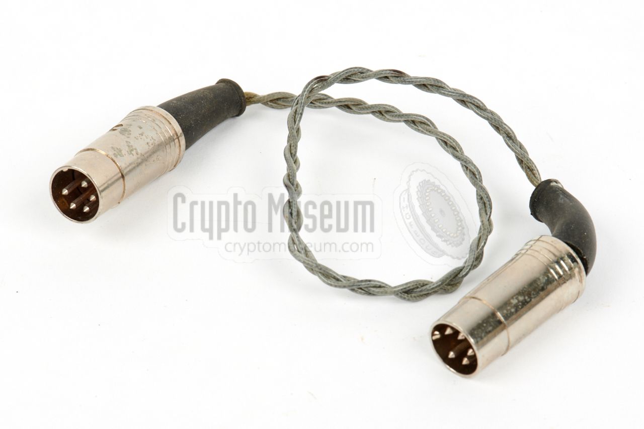
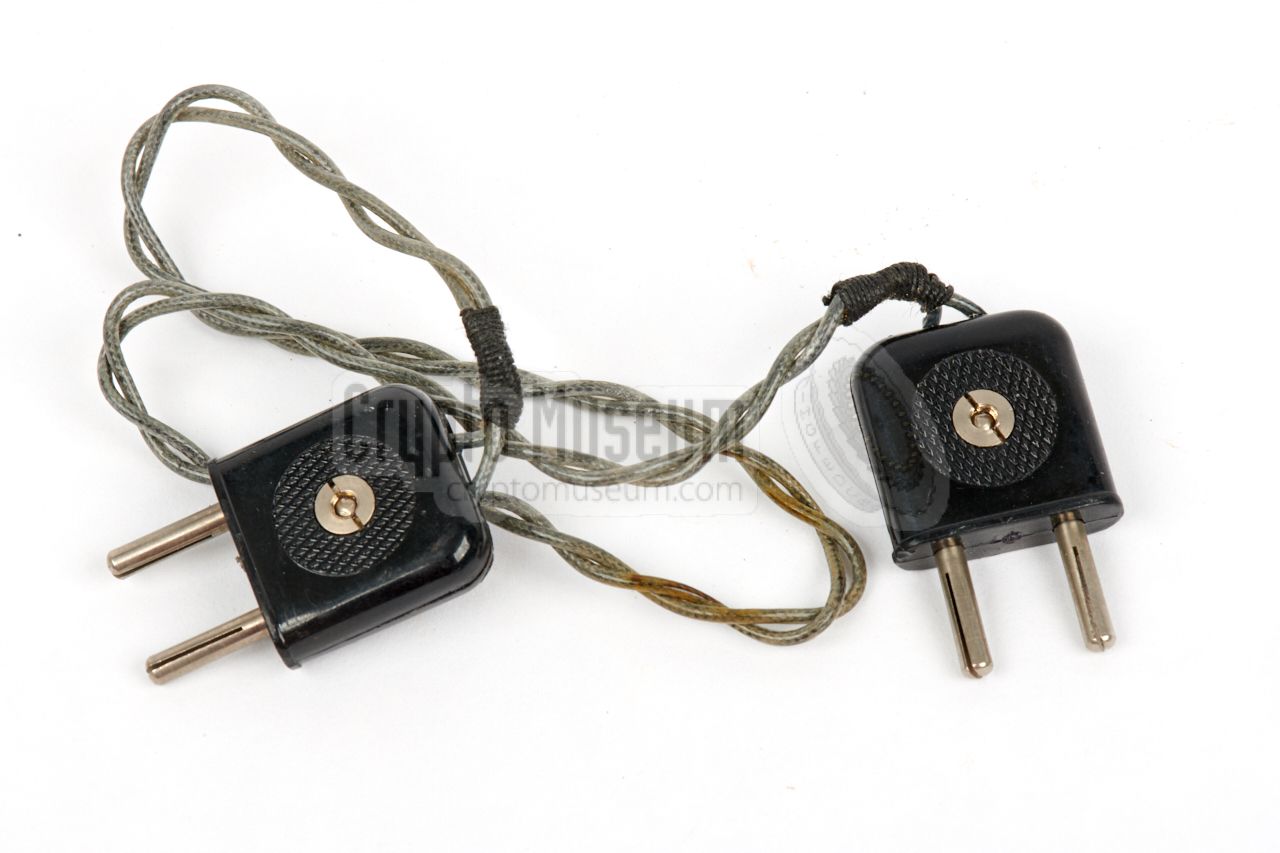
Two short cables were supplied with the kit: a DIN-DIN cable for connection
of the transmitter
to the PSU, and a 2-wire cable for connection of the
keyer
to the transmitter.
The pinout of the 3-wire DIN-DIN power cable is specified below.
Note that none of the wires is connected to the chassis of the transmitter.
The polarity of the 2-wire cable is irrelevant.
➤ Connections
|
|
|
For a proper operation, a wire antenna and a suitable counterpoise should
be connected to banana sockets at the rear of the transmitter. The length
of each wire depends on the desired transmission frequency.
The image on the right shows the antenna and counterpose wires, each wound
onto a pertinax (paxolin) card. The wires have several taps – each marked with
a number – that correspond to the tuning table
at the top of the transmitter.
|
|
|
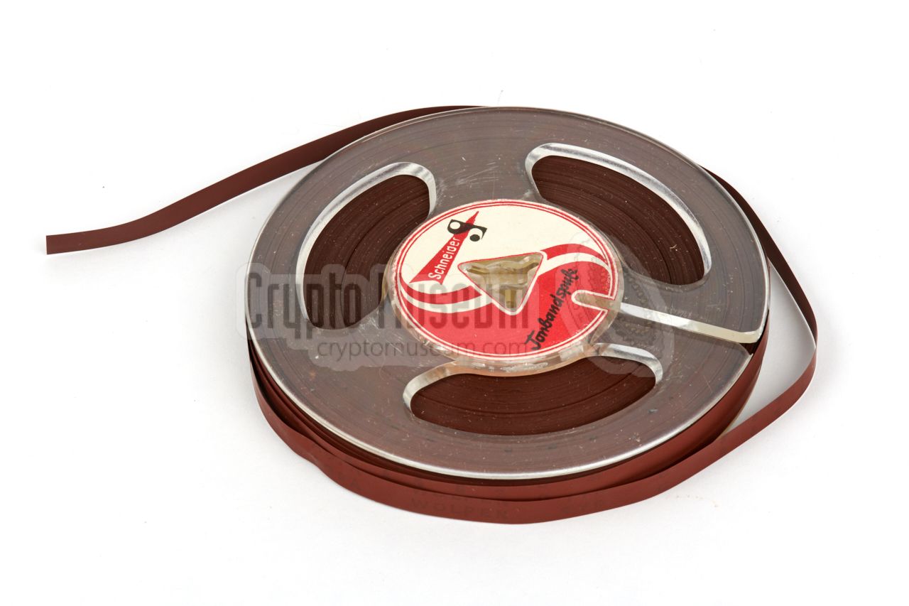
To allow the agent to send multiple messages, and re-use the transmitter
again in the future, a lot of extra magnetic tape was supplied with the kit.
First of all there were three small reels, two of which were filled with
regualar ¼" ferro tape.
In addition, a large reel with additional tape was supplied as spare.
Assuming that the messages were relatively short, this must have been more
than enough for a large number of messages.
And even if that was not sufficient, the
agent could get a new supply from any regular audio store in the West,
without attracting attention.
|
|
|
In order to allow the operator to repair the PSU and the transmitter
in case of a faillure, some spare parts were supplied as part of the kit.
This only involves socketet parts, which can easily be swapped by the agent.
The large valve is used in the transmitter's PA stage. The
smaller one is used in the oscillator.
The items were wrapped in paper and stowed in the cache containers without
further protection.
|
|
|
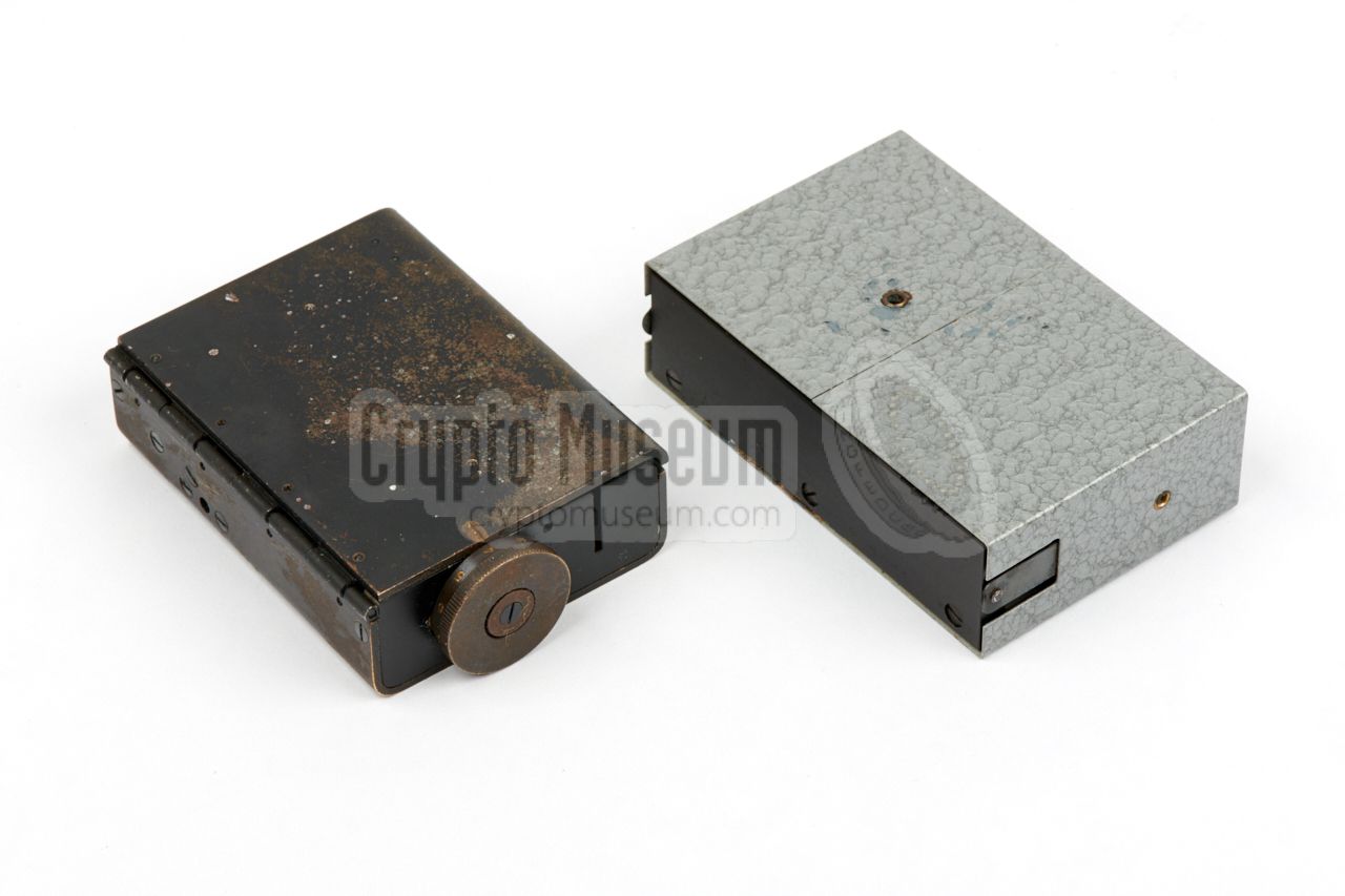
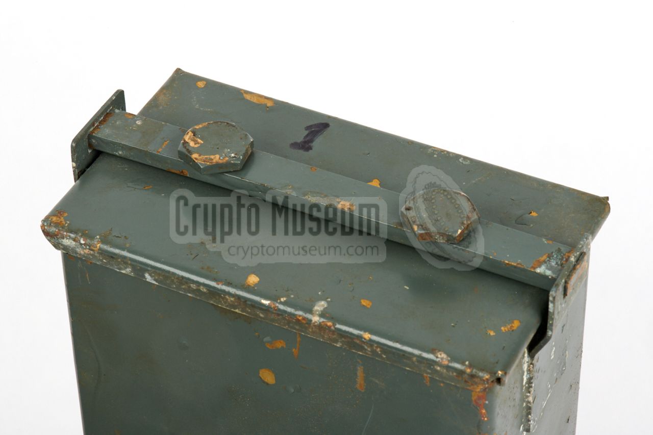
The complete radio station (except for an SW receiver) was stored in the two
watertight brass containers shown in the image on the right.
Each container has a rectangular lid that is
padded on the inside with
rubber. The lid is held in place by a
metal bracket with two hex bolts,
allowing it to be closed firmly. The colours are painted in traditional
Wehrmacht grey.
|
|
|
|
|
Concealment
cache container
|
|
|
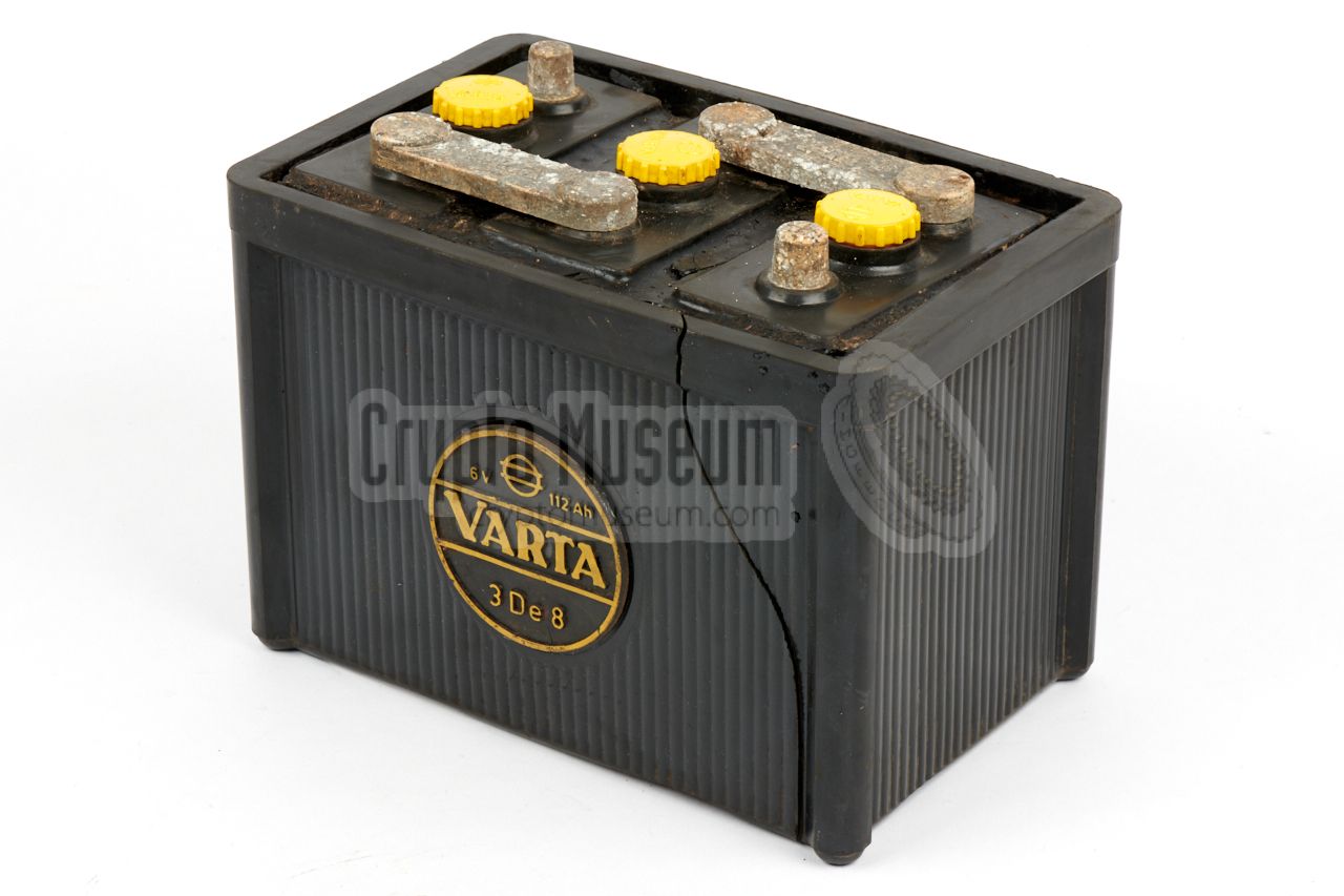
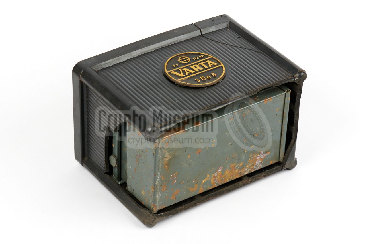
When the radio system was hidden in a secret underground cache, it was usually
hidden in some kind of common object that acted as a
concealment container.
In the case of the radio station featured here, it was hidden inside
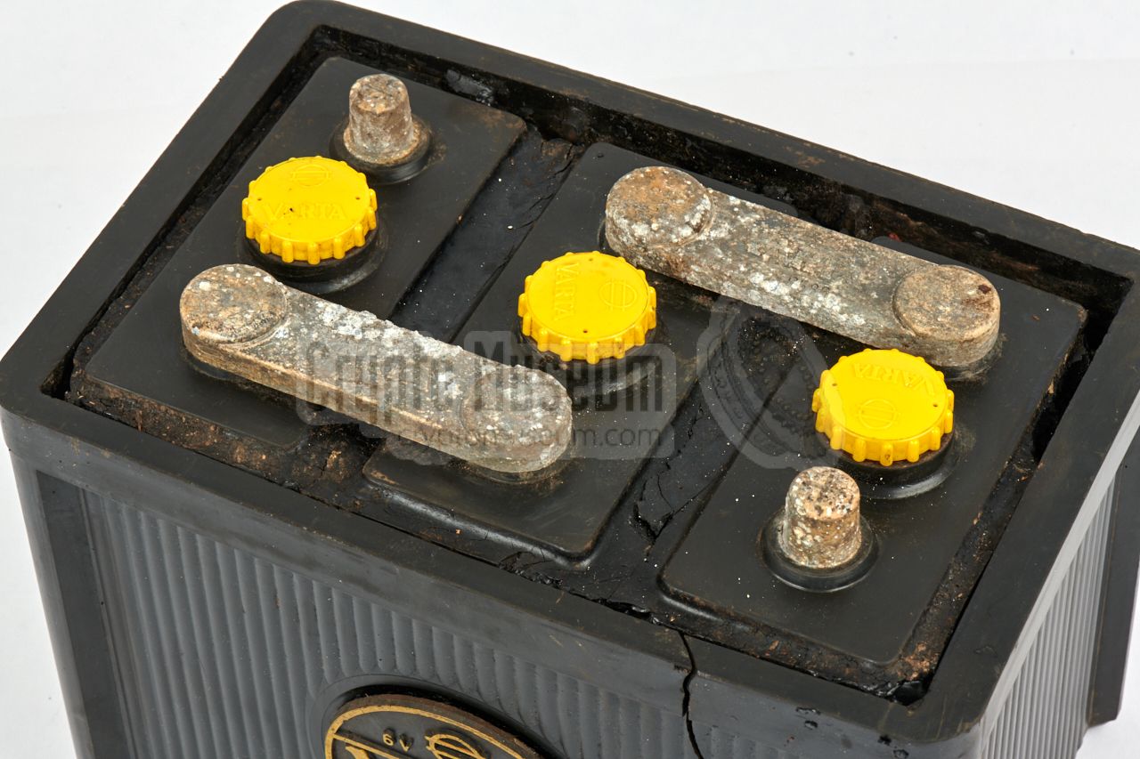
the regular VARTA 6V car battery shown here.
In fact, the concealment with the complete radio station shown here,
was found in a real cache in a
West-European country, as late as 2018.
➤ Read the full story
|
|
|
|
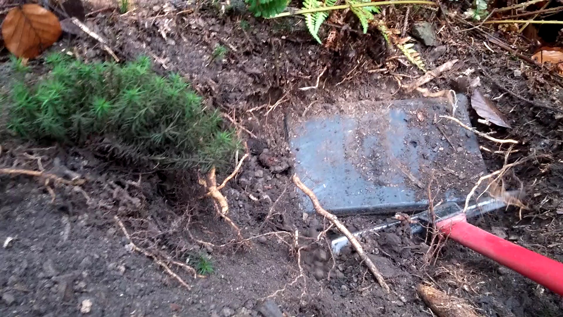
The spy radio set featured on this page, was (re)discovered in 2018 in a
West-European country, close to the border of The Netherlands.
It was found in a forest, burried approx. 20 cm deep, in a
secret underground hiding place, also known as a cache.
It had been there for nearly 60 years [1].
|
The cache was discovered by a fanatic amateur-archeologist by means of
a metal detector, and was concealed as a
VARTA 6V car battery of the 1960s.
At first sight, it seemed to be a regular battery that had been thrown
away a long time ago. Apparently undamaged and unmodified,
it even had the appropriate weight for a battery.
Curious about why someone would want to burry a regular car battery, and because
he heared a rattling sound when he turned the battery over, the archeologist
decided to knock out the sides with his pickaxe, and investigate the internals.
|
|
|
|
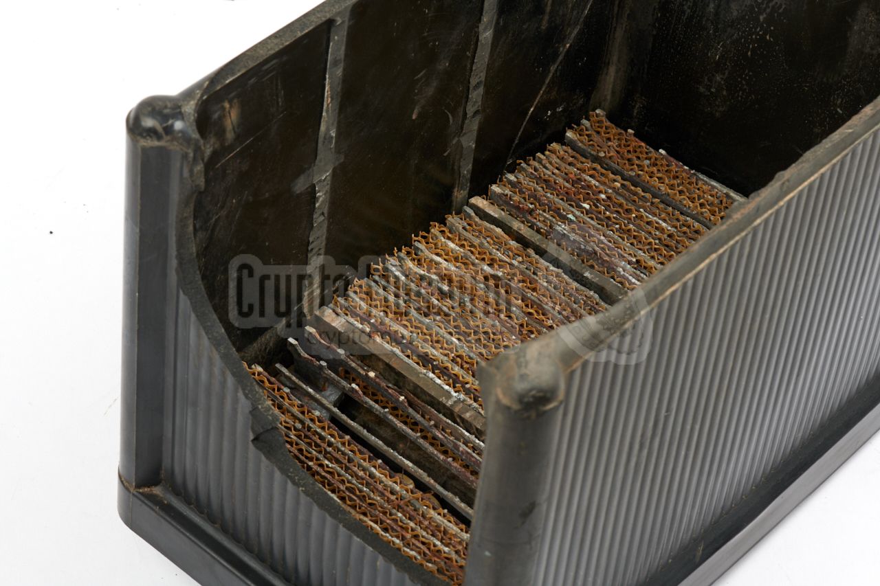
To his great surprise, there were
two rectangular watertight containers inside
the battery, padded with sheets of lead
to give the battery a more convincing weight.
At that point it became clear to him that this was not a regular car
battery, but more likely a secret cache
from the Cold War era.
|
The image on the right shows the concealment after the bottom and part of
one side of the battery had been cut away. Although the kit had been burried
in the ground for nearly 60 years, the two containers showed only minor signs
of corrosion, which proves that the concealment (i.e. the battery case)
has worked as intended.
After removing the two metal containers from the concealment,
it became clear that it might have been better to access it from the top,
by removing the tar rig between the top panel
and the outer case. The top can then be taken off.
|
|
|
The containers are marked 1 and 2 respectively and contain half the radio
set each. Some items are wrapped in paper, but the crucial parts – the
transmitter
and the PSU
– are each packed in a hermetically sealed plastic
bag. Note that the semi-transparent plastic bags feel sticky, which suggests
that the plasticizer used in the PVC base material has meanwhile become
volatile.
The PSU has been well protected by the plastic bag, as no corrosion
is found on the exterior. Inside the PSU,
the mains transformer exhibits
minor traces of rust that eare easily brushed off.
|
|
|
|
This proves that even though the items are packed in a hermetically sealed
bag, which is stored in a watertight container, which in turn is packed in
a watertight concealment, some air molecules will still be able to penetrate
the packaging and cause corrosion, especially after nearly 60 years.
|
In order to protect the delicate parts of the transmitter, its chassis
is made of zinc-plated metal. Furthermore a large
moisure eater is packed with
it inside the plastic bag. This way, the zinc on the chassis is used as a
sacrificial electrode, similar to a ship's sacrificial anodes.
The image on the right shows the corrosion at the bottom side of the
transmitter. As the parts inside the transmitter
are still 'as new' – even the silver-plated variable capacitors – this
method seems to have worked well.
With that in mind, it should be clear that the items of this particular
cache find are in exceptionally good condition.
|
|
|
|
Although there is some rust on the crystal boxes
and their lids, the crystals themselves are still in immaculate condition.
Surprisingly, the rubber bands
that keep the antenna wires on the paxolin
cards, are still fully elastic and have not become brittle over time.
More under Restoration below.
|
Looking at the remains of the concealment container, it becomes clear how
it was made. The Stasi
had taken an off-the-shelf 6V 1 car battery from the
West-German manufactuer VARTA, which would not raise any suspicion when
found in a free West-European country.
After removing the tar seem at the
top of the battery,
the interior (i.e. the
lead plates) was removed. The walls between the three battery cells were
removed, and the lead plates were cut-off. Only the parts of the interior
directly below the three filling points, were left intact.
|
|
|
|
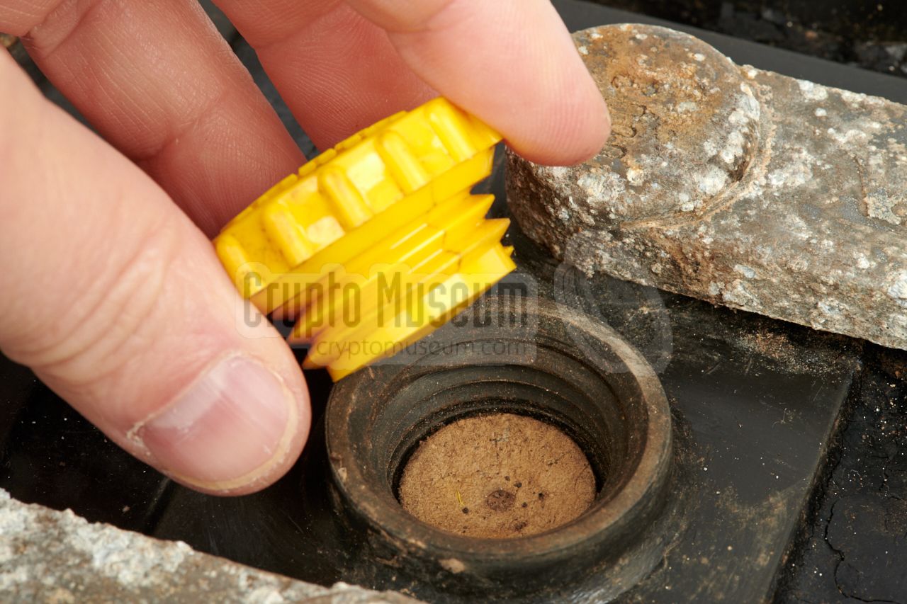
This way, it would still seem like a regular battery when someone would
remove one of the yellow caps and
look inside.
The two metal containers
– which were probably purpose-made – were then stowed in the hollowed-out
base, padded with some of the
original lead plates to give it a more
convincing weight. The top was then re-installed and the seem was sealed
again with black tar.
|
As an aside note, it is interesting to realise how every effort was made to
hide the fact that the transmitter was made in the DDR.
Although the DDR had its own electronics industry
(e.g. RFT),
only parts from Western manufacturers (mainly German and British) was used.
The main valve
in the transmitter was supplied by Haltron (UK), the
selenium rectifiers in the
PSU are from Siemens,
and the antenna current lamp is made by Osram.
The plugs and sockets are all made by
Kathrein and Hirschmann, and most of
the resistors
and capacitors are made by British manufacturers.
|
|
|
|
The transmitter and the PSU are extremely well-built, with is emphasized
by the fact that it still works after nearly 60 years of underground
storage under uncontrolled conditions. In the section
Restoration,
it is described how the device was brought back to life at
Crypto Museum in 2018.
|
-
Unlike today, where most cars have a 12V battery, many cars in the early
1960s still had a 6V battery. VARTA was one of the main suppliers of car
batteries in Western Europe.
|
|
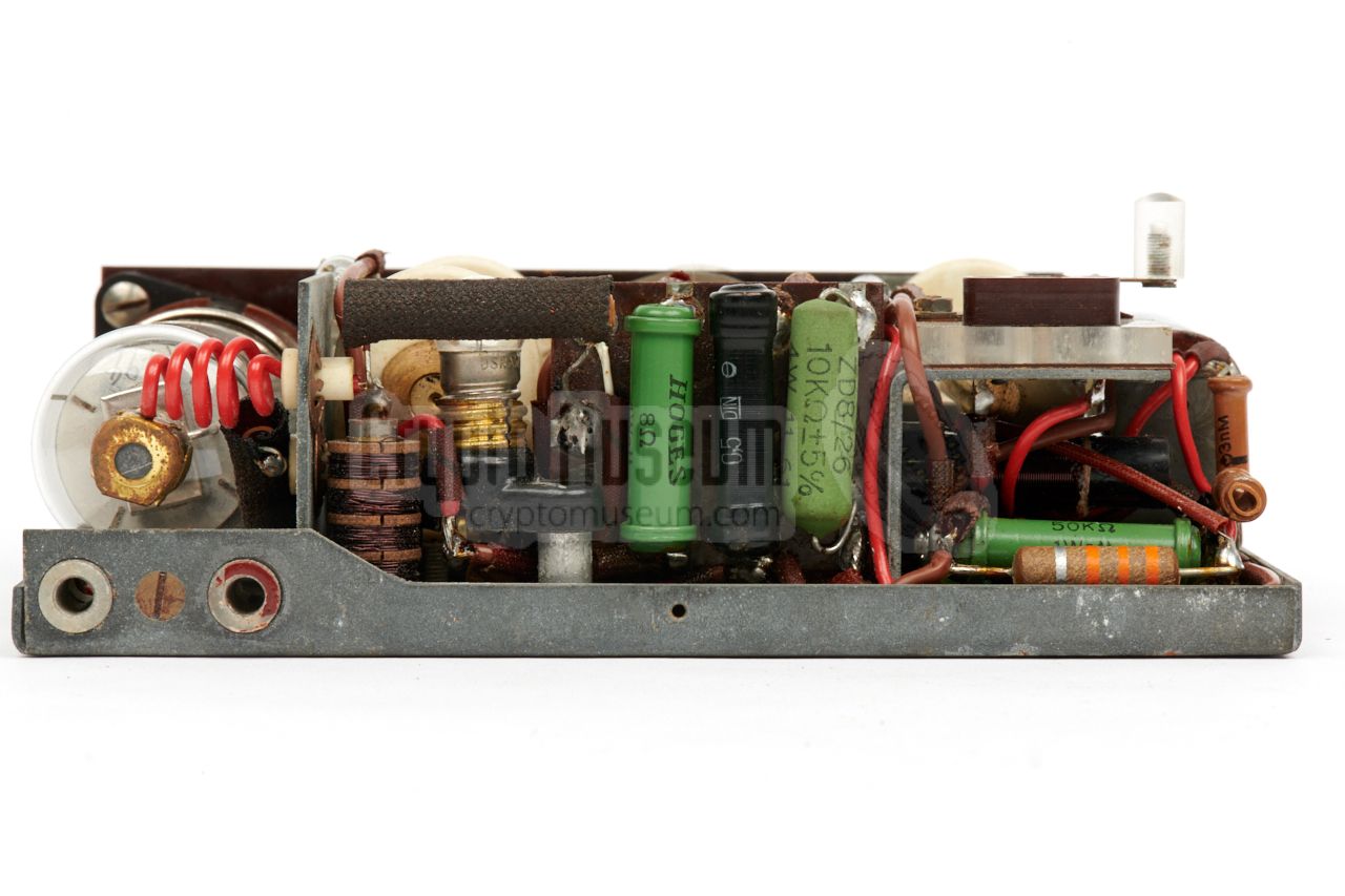
The transmitter measures 150 x 105 x 50 mm and weighs 914 grams.
It is housed in a metal grey hamerite enclosure, that consists of a
zinc-plated frame and a hamerite top section that is held in
place by four screws. The top panel is fitted with four recessed screws
at the corners.
|
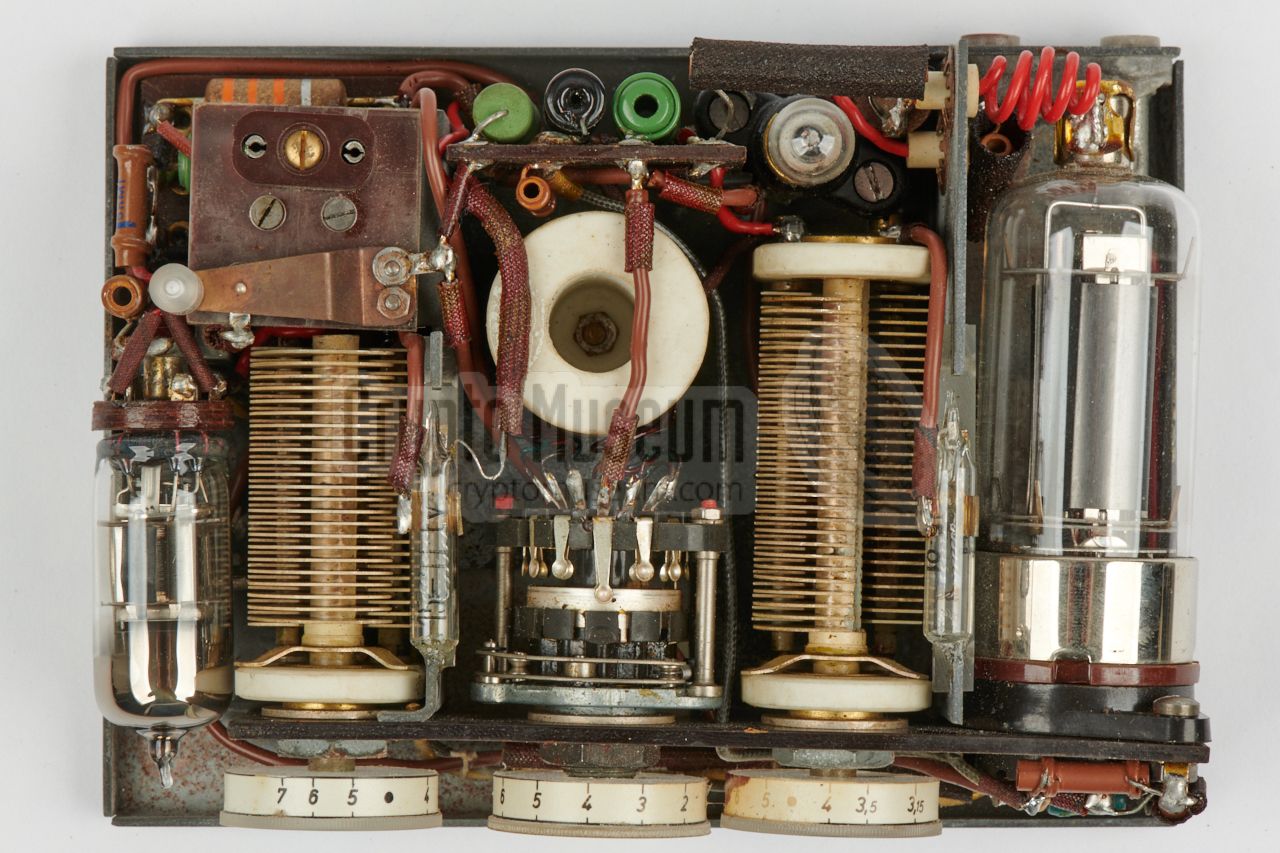
It is possible to remove just the top panel, or the entire case shell.
The image on the right shows the transmitter after removing the case shell.
At the front are the three circular tuning knobs.
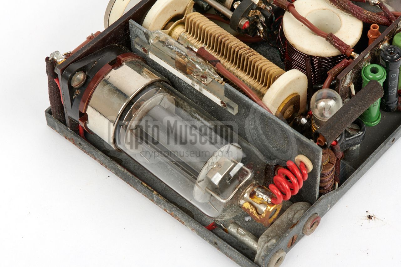
The transmitter is divided into three sections. At the left is the
oscillator,
which is built around a 6AG5 valve.
Just behind the valve socket, is the crystal socket. At the right is the
power amplifier (PA), which is built
around a 20W 2E26 valve.
At the centre is the antenna tuning circuit, in which
a seven-position rotary switch selects one of the seven taps of a large
antenna coil just behind it.
|
|
|
|
Together with the large adjustable capacitor to its right, the coil is part
of the tuned circuit of the PA. Both should be adjusted for the highest
output power at the desired frequency. The leftmost knob is for tuning
the oscillator. A table
on the top surface of the case, provides some presets.
|
There is no additional filtering, so the emission of
unwanted harmonic frequencies has
to be taken for granted. Although it is possible to adjust the tuning controls
in such a way that the harmonics are reduced, the agent had no way to check
this, and could only rely on the table(s).
The two voltages for the transmitter – 6.3V AC for the filaments and a
variable HT voltage for the anodes of the valves, are supplied by
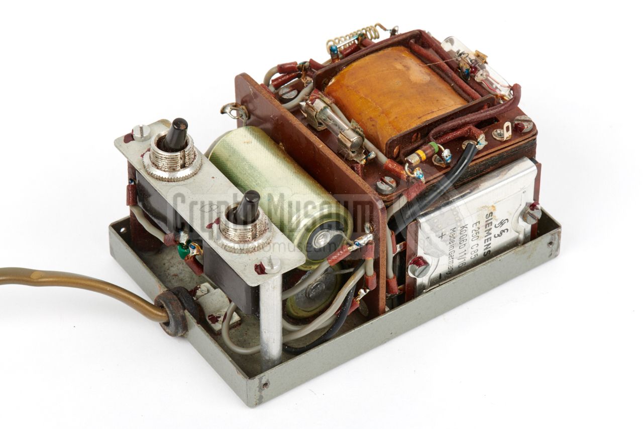
the power supply unit (PSU).
The PSU consists of a metal base frame that holds all components,
and a removable metal grey hamerite case shell.
|
|
|
|
The interior of the PSU – as shown in the image above – can be exposed by
removing the four screws from the lower edges of the sides, and lifting off
the case shell. At one side is the fixed mains cable. At the other side is
the 5-pin power output socket
that should be connected to the transmitter.
The PSU consists of a transformer, two selenium rectifier bridges
(made by Siemens), and two capacitors.
The output power of the transmitter is controlled with one of the switches
on the metal bridge at the left. It allows selection between 235 and 415V,
equivalent to 10 and 20W.
|
|
When we obtained the radio station featured here, it was in a well-preserved
state, especially when considering the fact that it had been burried in the
ground for neary 60 years. After a first rough inspection, it was thought
that it would be possible to bring the set back to life again.
|
The first item to be checked was, of course, the PSU. An intitial inspection of
the interior showed some minor rust on the mains transformer, but that was
easily brushed off. We also discovered that the fuse holder no longer
provided a good contact, and cleaned it with a small dental mill.
After checking the other components, a VARIAC was used to raise the mains
voltage gradually from 50V to 200V over a period of several hours, to give
the capacitors time to reform themselves. After a few hours, the PSU
produced stable LT and HT output voltages, without running hot.
|
|
|
|
It was decided not to raise the mains voltage above 200V AC, to prevent
the mains transformer from going into saturation, and to increase the life span
of the valves. Next, it was time to try the transmitter. The interior was
inspected thoroughly, but all components were free from corrosion.
|
Although the zinc-plated bottom panel of the receiver showed
some signs of corrosion,
the crystal socket was clean, as were the contact pins of
the valves. Even the two silver-plated adjustable capacitors were clean,
as if they had been installed yesterday. Apparently, the zinc chassis has
worked as a sacrificial anode.
As the transmitter has no electrolytic capacitors, there was no need to
run a reform cycle.
When we were certain that everthing was OK, it was deemed safe to
power it up. A 4.230 MHz crystal was
installed in the transmitter's crystal socket.
|
|
|
|
The power cable was installed between the PSU and the transmitter,
and the PSU was connected to the mains (via the VARIAC, set to 200V).
The neon lamp on the PSU came to life immediately, and
after a short while, the filiments of the valves also lighted up.
The RF power selector was set to 10 Watt (RF power switch set to ● )
and the HT voltage was enabled (HT power switch set to ● ).
|
This caused the leftmost neon lamp on the top surface of the transmitter
to light up.
A suitable dummy load was connected to the antenna and counterpoise
sockets at the rear,
and the tune button (in front of the crystal)
was pressed. The transmitter came to life immediately, and with the
knobs at the front, the optimum was found.
The transmitter produces a strong and stable signal at the fundamental
frequency, but also produces strong unwanted harmonics, with the f2 being only 3dB down. Furthermore, the f3 is only 10dB down and the
f5 is just 20 dB down.
|
|
|
The inside of the lids of the crystal boxes, was padded with a thin bright
green foam, which had almost fully desintegrated. As it affects
the metal crystal enclosures, it was decided to remove it,
and replace it with a thin layer of felt with the same colour.
Any rust on the body of the crystal boxes was removed superficially, but was
otherwise left intact. Only a small spot on the top surface of the transmitter
was restored, in order to prevent the existing paint from coming off.
The following restorations have so far been carried out:
|
- PSU fuse holder repaired
- Minor rust removed from mains transformer
- Regeneration of the PSU capacitors
- Foam in lid of crystal boxes replaced by felt
- Minor paint repairs
- Cleaning and oiling of the puncher
- Plastic bags removed and stored elsewhere
|
- +HT +235V or +415V DC
- not connected
- Common
- LT 6.3V AC
- not connected
|
|
Device Clandestine SW transmitter Purpose Agent-to-Base communiction Model DDR Type 2 (see note 1 ) Design OTS Manufacturer unknown Year ~ 1962 Country East Germany (DDR) Frequency 3.15 — 7 MHz (in reality: 3.15 — 8.5 MHz) Output 10 or 20 Watts (selectable on PSU) Modulation CW (keyed)
|
-
As the original designator is unknown, we are using the nickname
'DDR Type 2', as suggested by Louis Meulstee in [2].
|
|
The following 30 quarz crystals were supplied with the kit (frequency in kHz):
|
- 3152
- 3318
- 3498
- 3670
- 3783
- 3878
|
- 4047
- 4187
- 4230
- 4323
- 4555
- 4743
|
- 5158
- 5202
- 5410
- 5530
- 5548
- 5715
|
- 6250
- 6310
- 6363
- 6570
- 6657
- 6807
|
|
|
- Bundesamt für Verfassungsschutz (BfV), Germany
- Bundeskriminalamt (BKA), Germany
- Crypto Museum, Netherlands
|
- Anonymous, DDR 'Type 2' transmitter in cache concealment
Crypto Museum, December 2018.
- Louis Meulstee, Wireless for the Warrior, volume 4
ISBN 0952063-36-0, September 2004
- Louis Meulstee, 'Type 1-4' GDR
Supplement Chapter 57, July 2016.
- Detlev Vreisleben, Personal correspondence
June — December 2018.
|
|
|
|
Any links shown in red are currently unavailable.
If you like the information on this website, why not make a donation?
© Crypto Museum. Created: Sunday 02 December 2018. Last changed: Wednesday, 05 November 2025 - 12:05 CET.
|
 |

|
|
|


