|
|
|
|
|

|
|
← CZ Cold War 300 AB →
Short range 20W short wave transmitter
The 300-A was a valve-based short-wave
spy radio transmitter for the
10-18 MHz frequency range, developed in
Czechoslovakia
in 1961 by
Správa 6 1 for use in foreign espionage by the
secret state police (StB)
and by Správa 1 (espionage).
The 20W transmitter was suitable for short-range communication
and was first used in Angola in 1961. The transmitter could be converted
for long-range communication by adding the external
300-B 200W power amplifier
to the set.
|
The unit has a built-in power supply unit (PSU) and is powered directly by
the 220V AC mains. It has
five banana sockets at the front panel for connection
of an automatic morse keyer.
A manual morse key can be
connected as well.
The transmitter produces an output power of 20W, which is suitable for
short-range morse communication.
At the left side of the unit is a PL519 coax socket
for connection of a small antenna tuner
(shown here on top of the device).
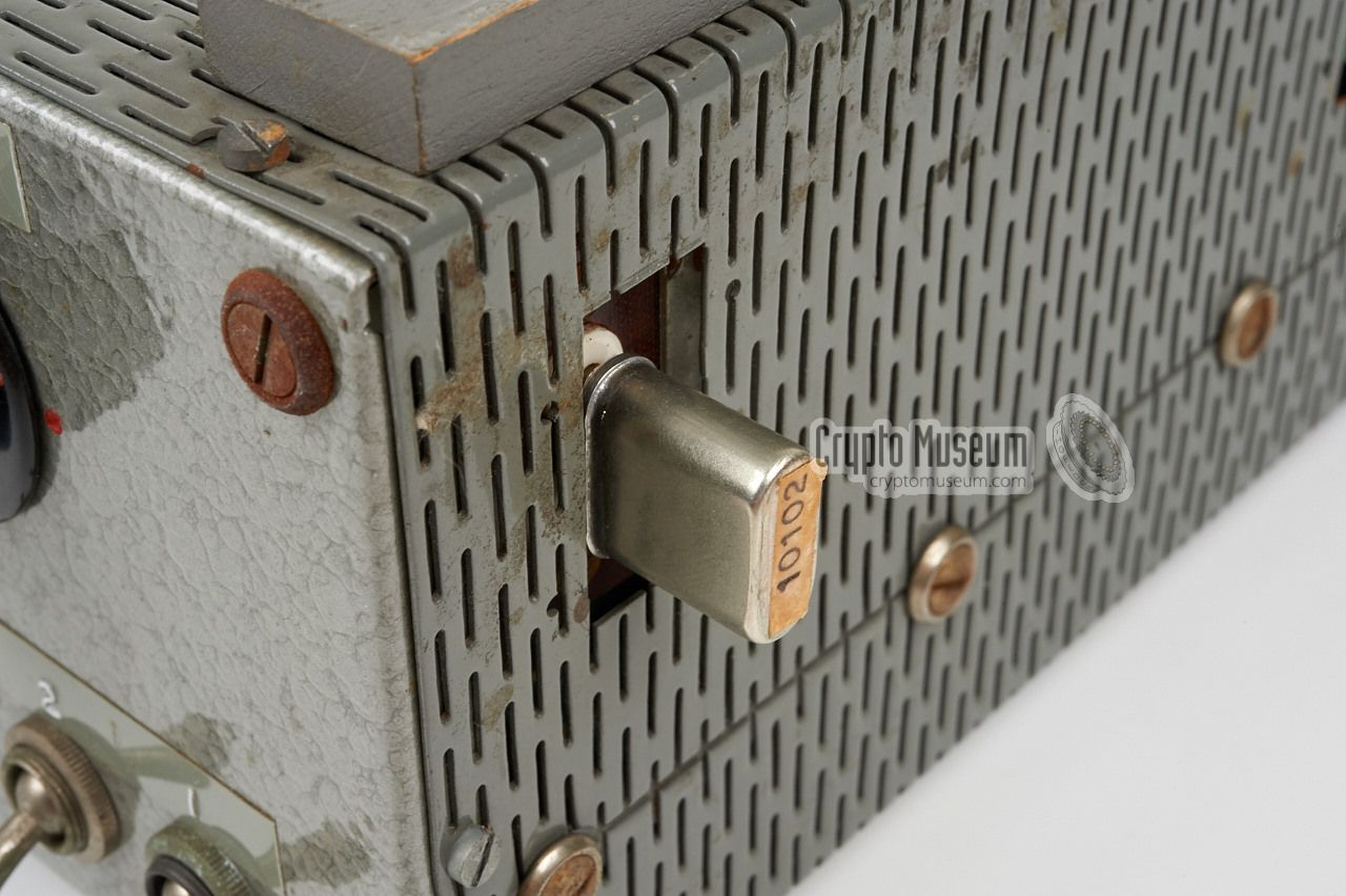
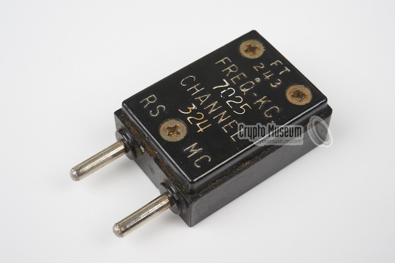
The frequency is determined by a crystal that should be inserted into the
socket at the right.
|
|
|
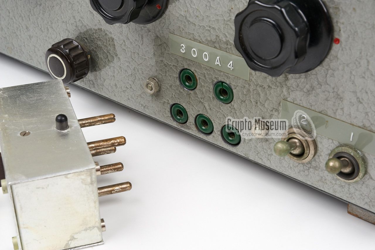
The 300-A was probably produced in small quantities, as the unit has no
project number and no engraved text on the front panel. Instead, the text
and the model number are applied by means of Dymo™ labels.
No documentation and/or circuit diagram is available at the moment.
The unit was used in Angola (1961) and, as the
300-AB,
in Congo (1961)
and Kurdistan (1965-1968).
|
-
Správa 6 refers to Government Department 6: Communication Technology.
|
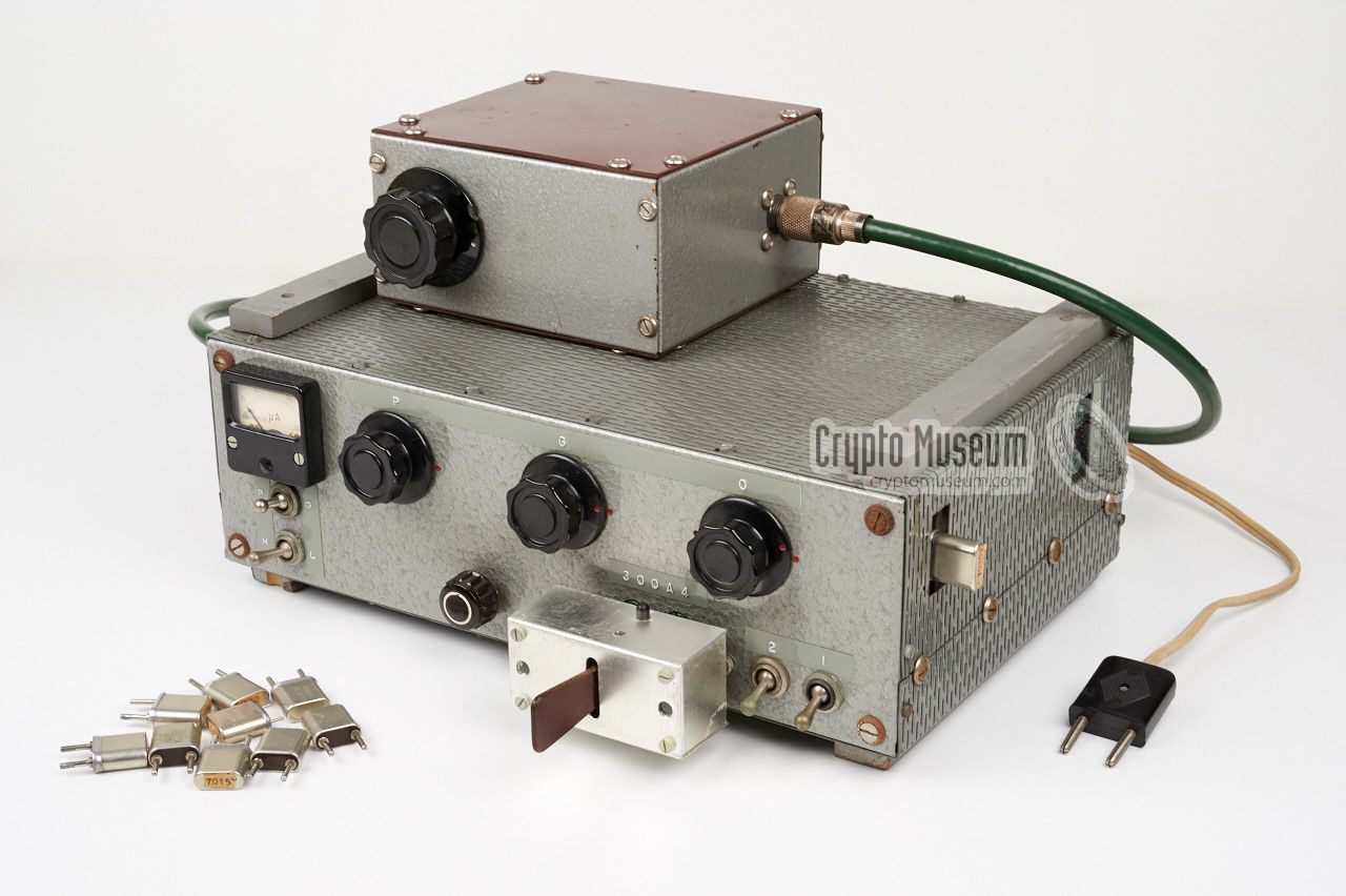
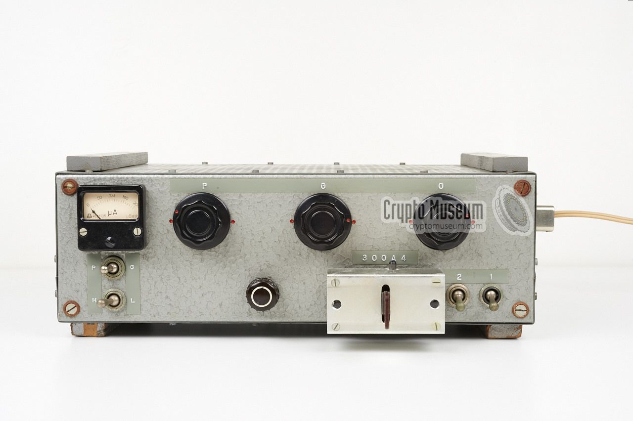
The diagram below shows the location of the controls and connections on the
300A transmitter. Note the four wooden strips at the upper and lower sides
which are necessary for providing sufficient cooling, especially when the
300B Power Amplifier is installed on top of it. The unit can be
connected directly to the 220V AC mains and a filtered 220V outlet is available
for the 300B. Power is applied in two stages: (1) the LT for the filaments,
and after a while (2) the HT voltage.
An asymmetrical antenna can be connected to the PL519 socket at the left side.
A symmetrical antenna, such as a long-wire or an inverted-V,
can also be connected
if the external antenna tuner is used.
Like the transceiver, the matcher should be tuned for maximum antenna current.
Five green banana sockets
are available on the front panel for connection
of an automatic morse keyer.
The keyer has a paddle sticking out at the
front. Pushing the paddle to the left produces a series of dots,
whilst pushing it to the right produces a series of dashes.
The speed can be set with the speed-knob.
A small button on top of the keyer
is used for tuning the transmitter.
If necessary, a standard manual morse key can be
connected to the upper two banana sockets.
Three large knobs on the front panel are provided for tuning the transmitter.
They are marked (from right to left) O (oscillator), G (grid)
and P (plate). The O-knob is used for adjusting the crystal's overtone,
whilst the G and P-knobs are used for tuning the transmitter's output power
in combination with the meter.
For this reason the P/G selector is available just below the meter.
|
For longe-range radio traffic, the transmitter could be enhanced
with a 300B Power Amplifier,
which increased the 20W from the transmitter
to a massive 200W. It was placed on top of the transmitter and came with
a dedicated 300C Antenna Tuner, as shown in this image.
The enhanced set was known as 300AB and was first used
in Congo and later also in Kurdistan.
➤ More information
|
|
|
|
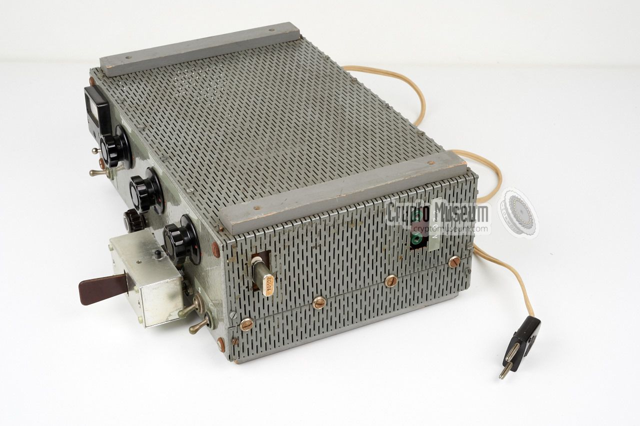
The 300-A transmitter is housed in a grey hammerite enclosure that measures
33 x 23 x 12.5 cm. The construction consists of an aluminium frame, a front
panel, a rear panel, an upper case shell and a lower case shell. Both shells
are made of perforated metal, so that the electronics are properly cooled.
For this reason wooden rigs are provided at the edges of the case as
spacers.
|
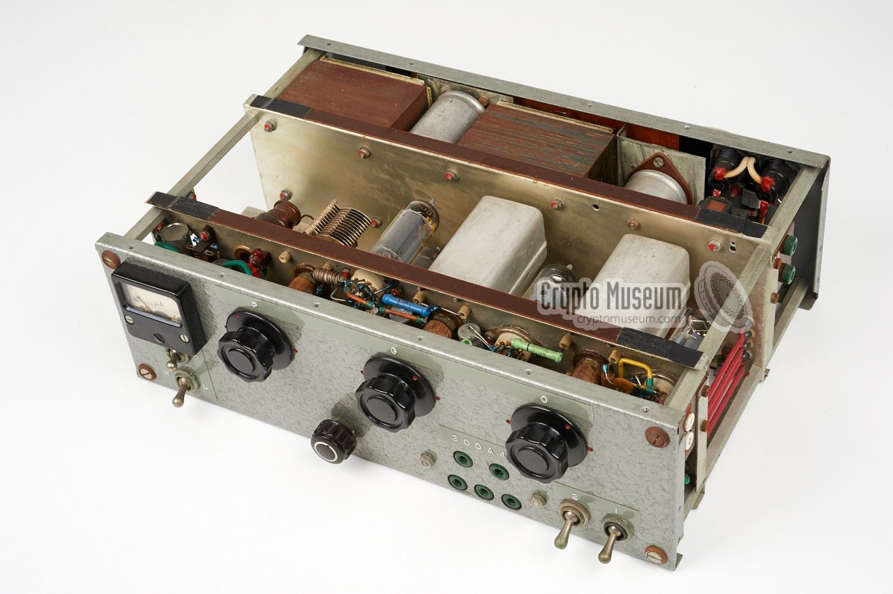
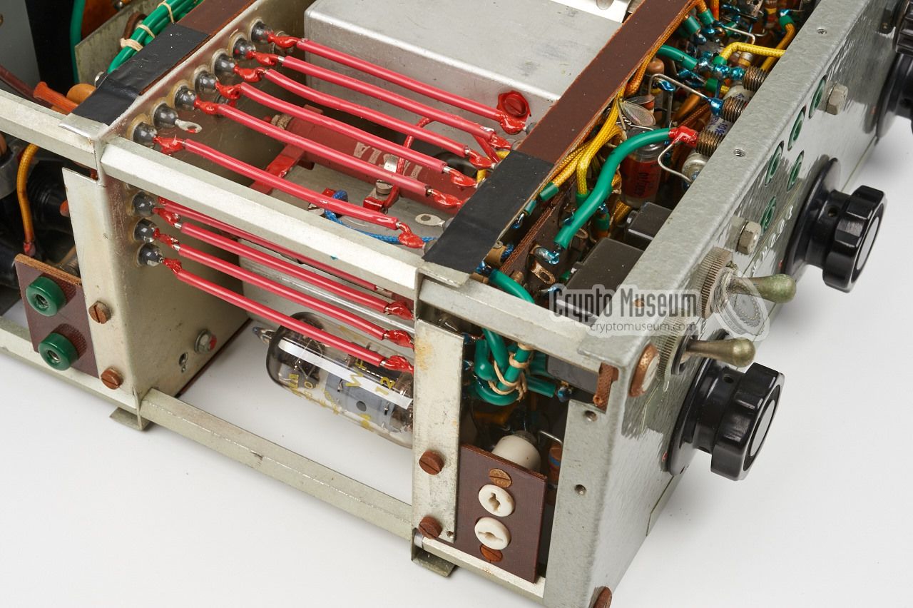
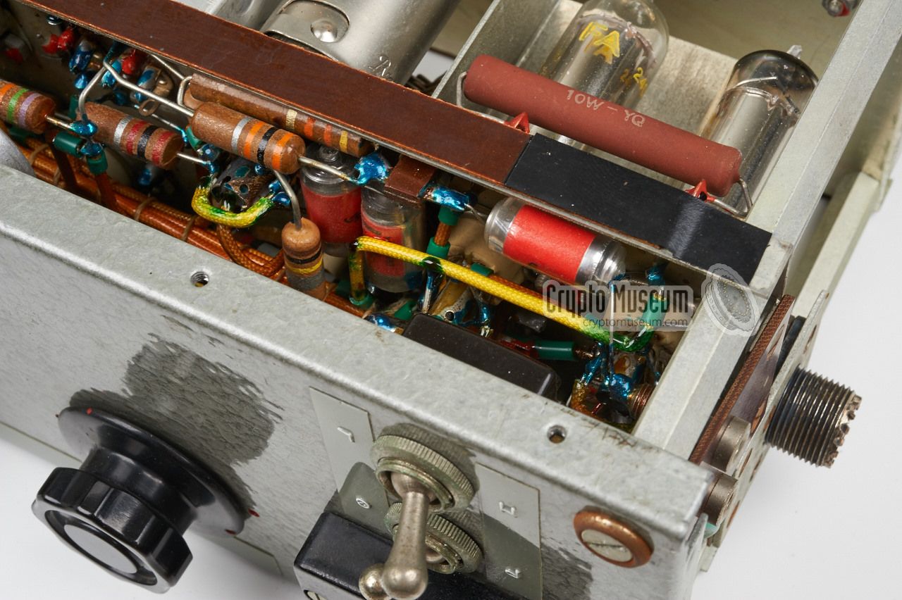
Despite its relatively boring exterior, the 300-A is extremely well
built. It consists of no less than nine valves, three of which (ECC82)
are used for the automatic morse keyer
which also uses two large telephone relays for the dots and dashes.
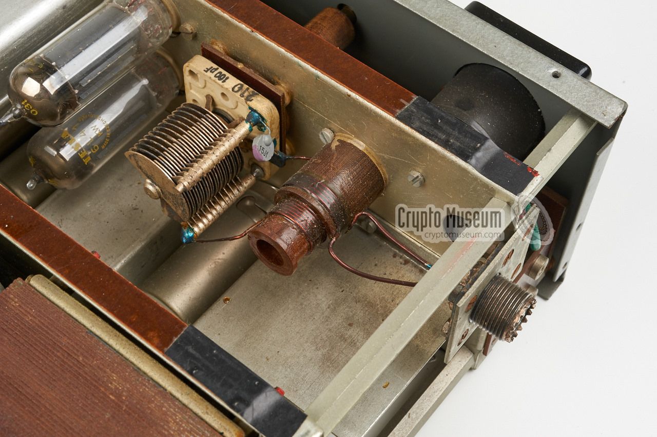
The valve closest to the crystal socket is the
oscillator, which the one next to it being
the doubler or tripler. The output stage
of the transmitter consists of
two 6L41 valves in a balanced circuit, producing approx. 20W output.
The output stage is shown in the image on the right, as seen from the rear
of the device.
|
|
|
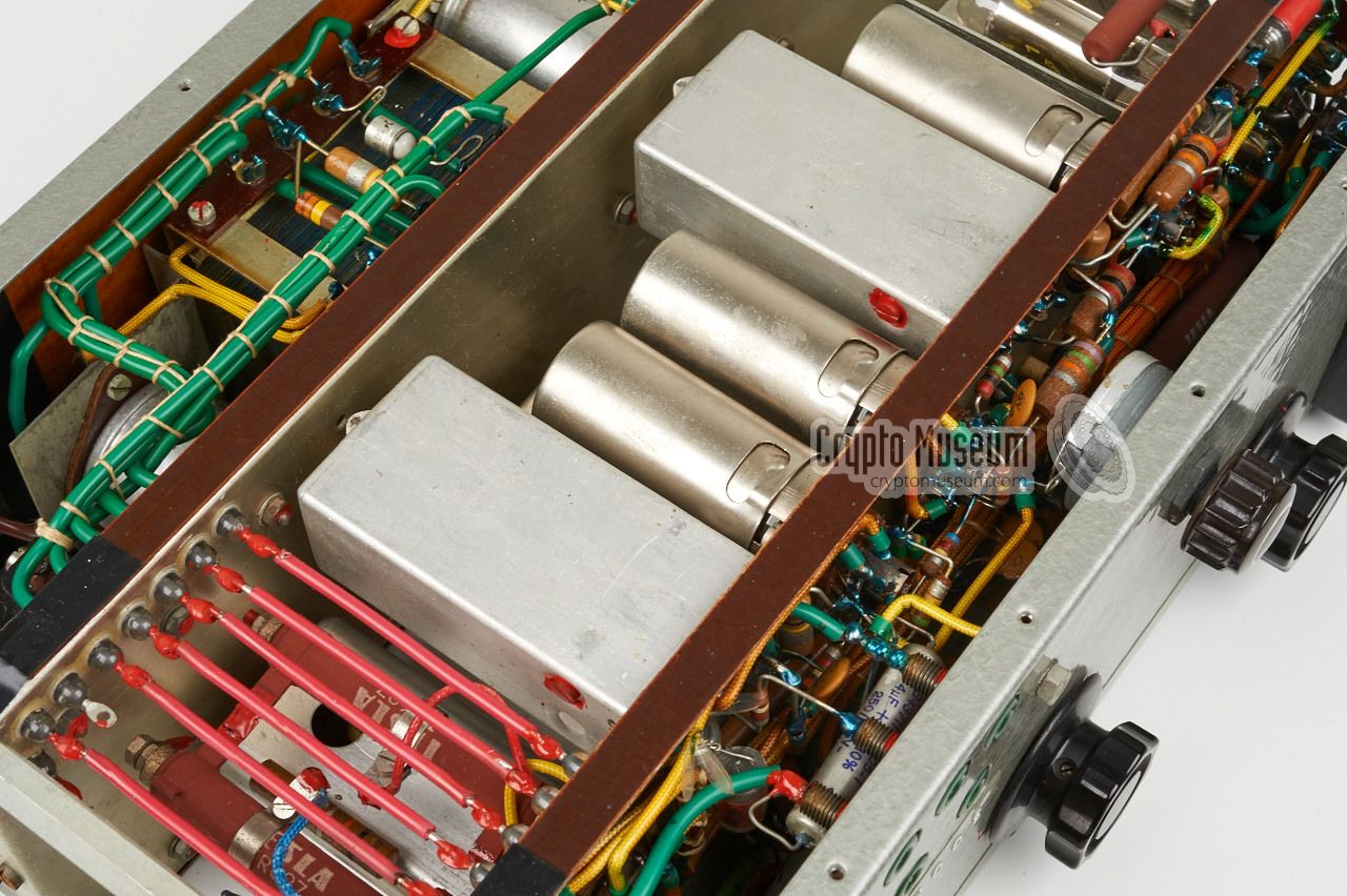
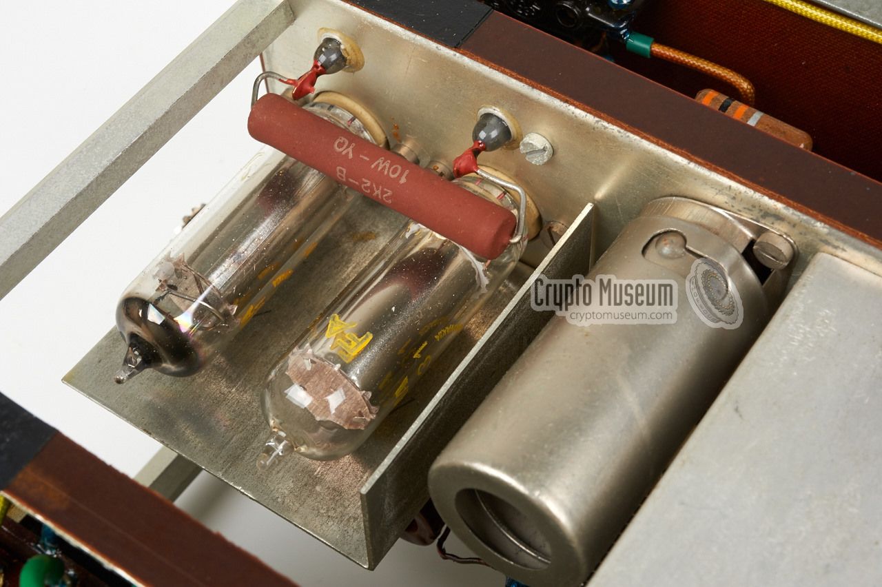
The chassis roughly consists of three compartments: the electronics at
the centre, the control panel at the front and the power supply at the
rear. In the centre section, all HF valves are mounted at the
top side,
whilst the valves of the automatic keyer are
mounted at the bottom.
|
EF80 Oscillator 6L43 Multiplier 2 x 6L41 PA 11TA31 Voltage regulator 14TA31 Voltage regulator 3 x ECC82 Morse keyer
|
300-A4 Transmitter 20W 300-B5 Power Amplifier 200W 300-C3 Antenna tuner for 300-B ? Antenna tuner for 300-A
|
|
The 300 A and the 300 AB were used in the following countries:
|
Angola 1961 (300A) Congo 1961 (300AB) Kurdistan 1965-1968 (300AB)
|
- Anonymous, 300-A transmitter and accessories - THANKS!
Transmitter kindly donated by anonymous former user. July 2015.
|
|
|
|
Any links shown in red are currently unavailable.
If you like the information on this website, why not make a donation?
© Crypto Museum. Created: Wednesday 19 August 2015. Last changed: Wednesday, 28 February 2018 - 22:40 CET.
|
 |

|
|
|