|
|
|
|
|

|
|
Poland WWII BP-5 → ← AP-5
Polish WWII spy radio set
The BP-3 was a valve-based spy radio transceiver,
developed during WWII by Tadeusz Heftman of the
Polish Military Wireless Unit
(Polski Wojskowy Warsztat Radiowy) in Stanmore (UK) [1].
It was introduced in 1943 and was intended for use by agents and
resistance organisations in Europe.
|
The 'B'-series of radio sets (from 1943 onwards: 'BP') were produced
alongside the 'A'-series and featured increased power output.
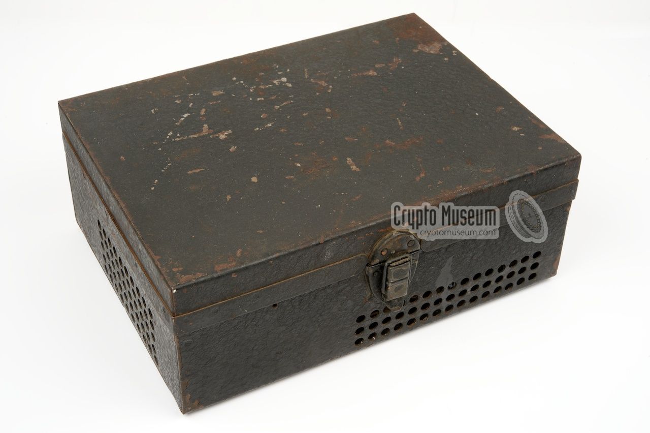
The sets were housed in a black wrinkle-finished metal box with a lid,
and were labelled in Polish or English.
The BP-3 covers 2-8 MHz and is built around 6 valves, all of which are mounted
internally. It the field it was powered by a 12V DC converter with
rotary transformer, but it could also be powered by the external 120/220V AC
Power Supply Unit (PSU) that was connected to the 5-pin socket on the
front panel, just like on the other BP-models.
|
|
|
The BP-3 measures just 28 x 21 x 11 cm and weighs less than 6 kg.
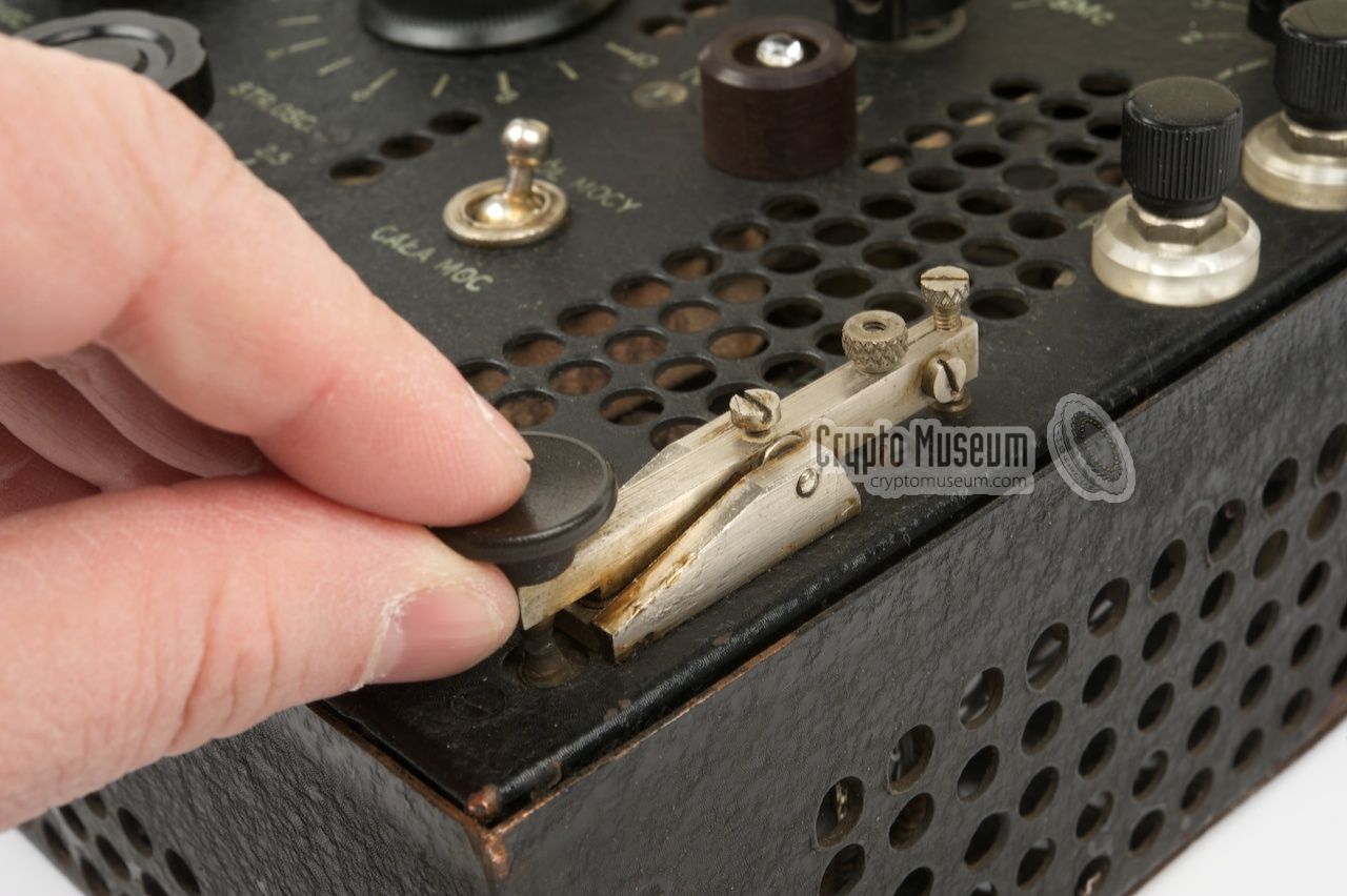
It uses a long wire or dipole antenna and came with a full set of accessories,
including power cables, crystals, antenna and counterpoise wires, external
morse key, a mains power supply unit (PSU) and a 12V DC converter.
The exernal power supply unit (PSU) measures 9.5 x 21 x 28.5 cm and
weighs just over 10 kg.
The transmitter produces an output power of 50 Watts in CW, which is more than
the larger and havier British Type 3 Mark II (B2).
Apart from the Polish Resistance in occupied Europe,
the BP-3 was also used by the SOE (in Europe and in Asia),
and the French, Czech and Yugoslav Resistance.
For several years, the Polish spy radio sets
were superior to their British counterparts.
The BP-3 was succeeded by the BP-4, which had a different
frequency range (4-16 MHz) and eventually in 1944 by the BP-5,
which covered the same 2-8 MHz but had a built-in AM (voice) modulator.
|
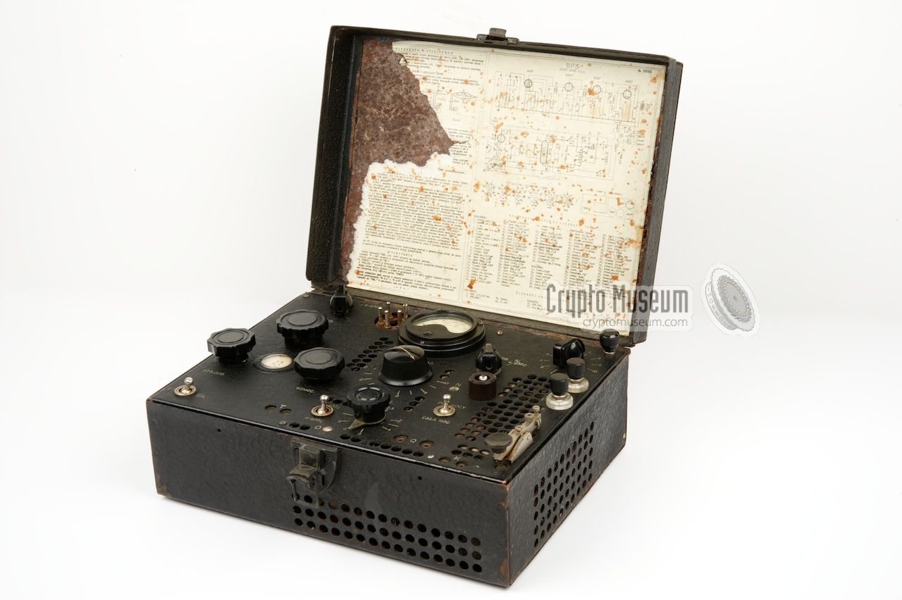
The BP-3 has a clear and well-organised control panel which is shown below.
The area left of the yellow dotted line is used by the receiver, whilst the
remaining space is taken by the transmitter. The receiver has a small circular
tuning dial at the center, with two knobs (course and fine) for adjusting
the frequency. The other knob is for adjusting the volume.
The full frequency range is divided over two bands (2-5 MHz
and 5-8 MHz) selectable with the black knob at the top left. The receiver
is suitable for phone (F) and CW (Gr), selectable with the switch
at the bottom left.
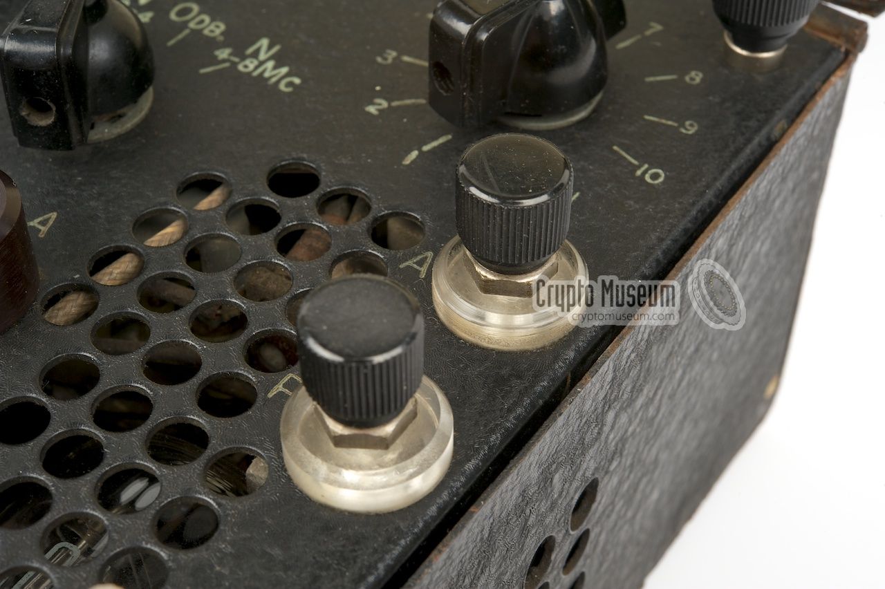
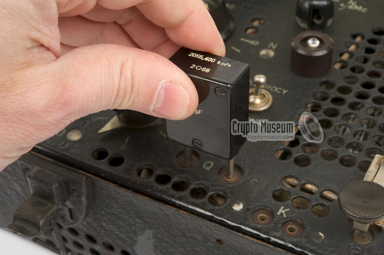
The transmitter is more complex and has a large number of adjustments and
indicators. First of all, a suitable crystal has to be installed in the
socket marked 'Q' along the bottom edge.
Next the Oscillator (OSC) and the Power Amplifier (PA) both have to be set
to the desired frequency range (2-4 or 4-8 MHz).
A toggle switch at the centre is
used to set the required ouput power: PÓŁ MOCY (half power) or CAŁA MOC (full
power). Once the transmitter is enabled, the three tuning knobs have to
be adjusted for maximum brightness of their indicators. At this point the
current meter at the top centre should read approx. 110 mA (or 210 mA
when at full power is selected).
The front panel of the later BP-5 (mid-1944) is nearly identical to that
of the BP-3, with the main difference being an extra 4-pin socket along the
bottom edge of the front panel of the BP-5. This socket was used for the
AM (phone) modulator extension.
The intermediate BP-4 (1943/44) is also nearly identical to the BP-3
but has a different frequency span (4-16 MHz).
|
|
The BP-3 is housed inside a wrinkle-finished black metal case that resembles
a trademan's toolbox of the era. The external Power Supply Unit (PSU)
is housed in a similar albeit smaller case.
The Poles believed that, when carried around in occupied Europe,
such toolboxes attracted far less attention than the leather suitcases
in which most British spy radios were transported.
|
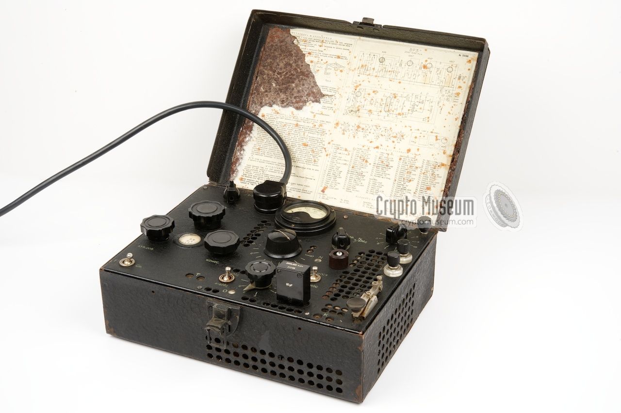
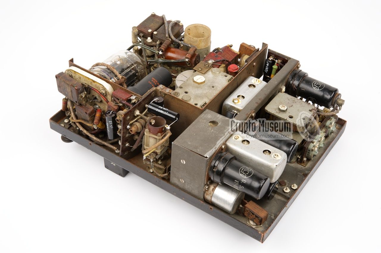
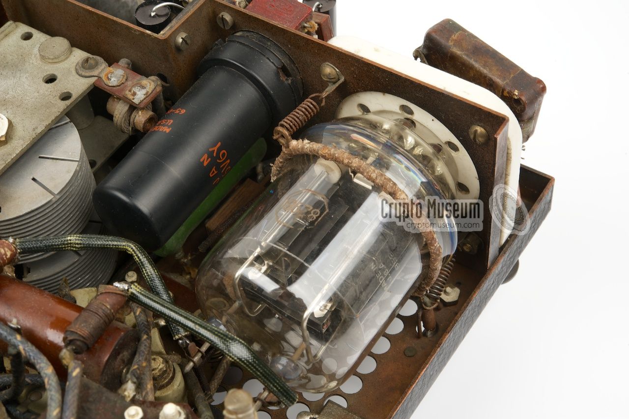
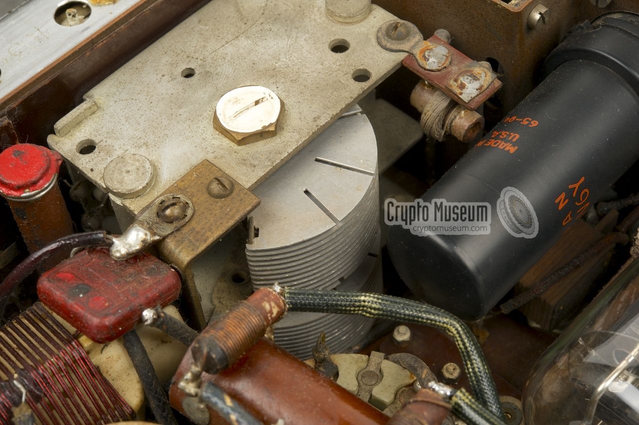
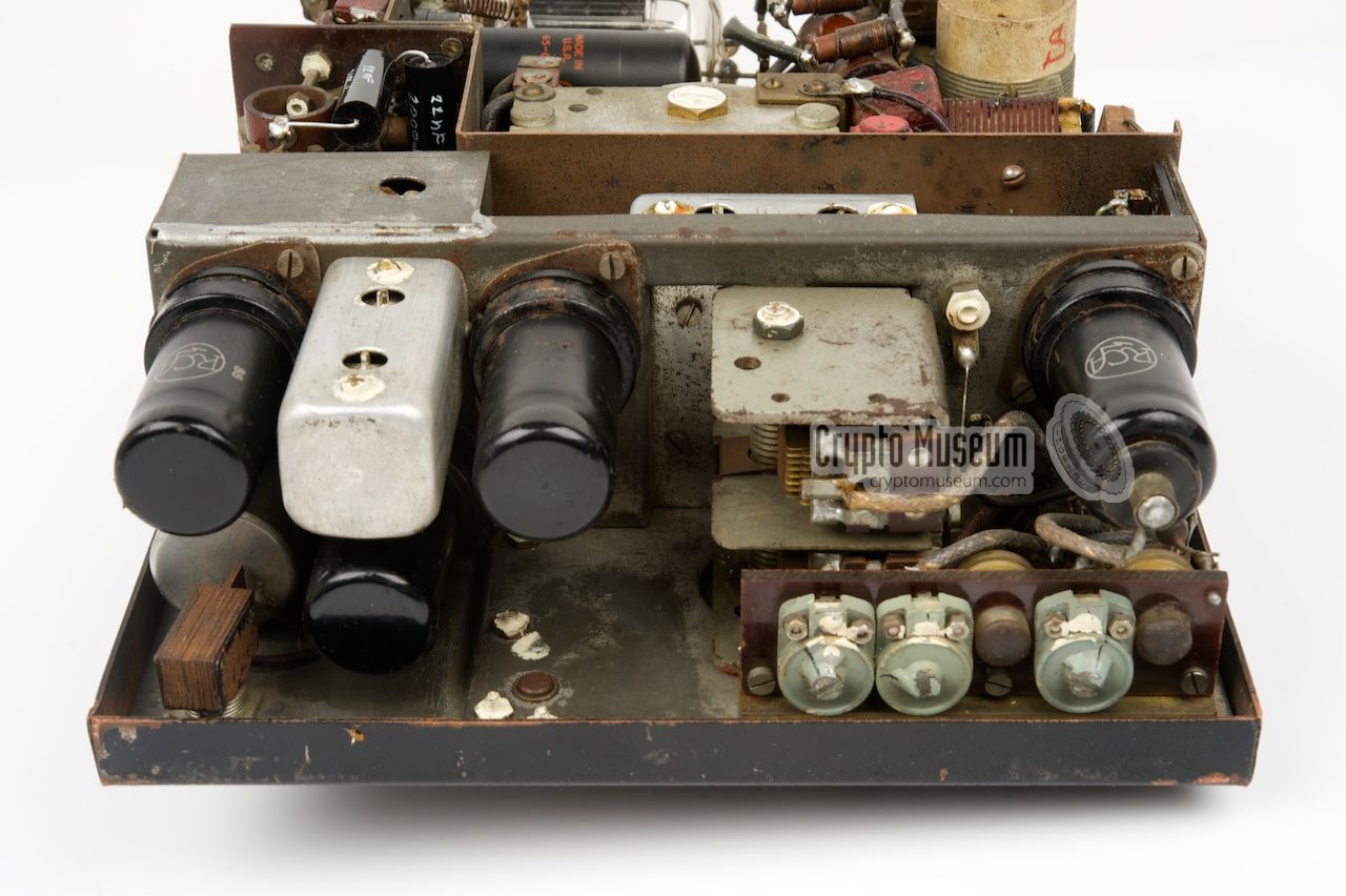
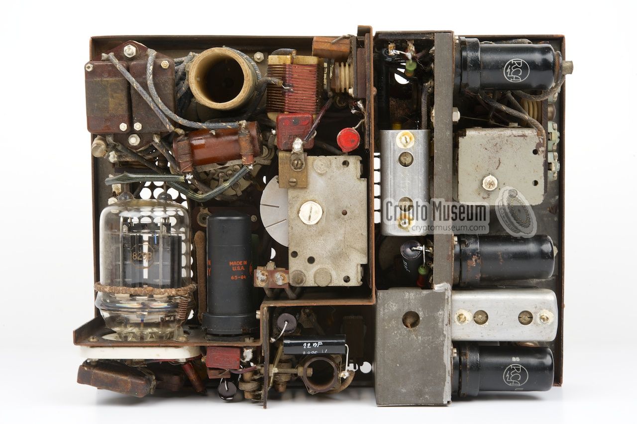
All components inside the BP-3 are mounted to the control
panel, which is held in place by four bolts:
two at the front and the at the rear.
After removing these bolts, the control panel can be lifted from the metal
box, revealing the interior.
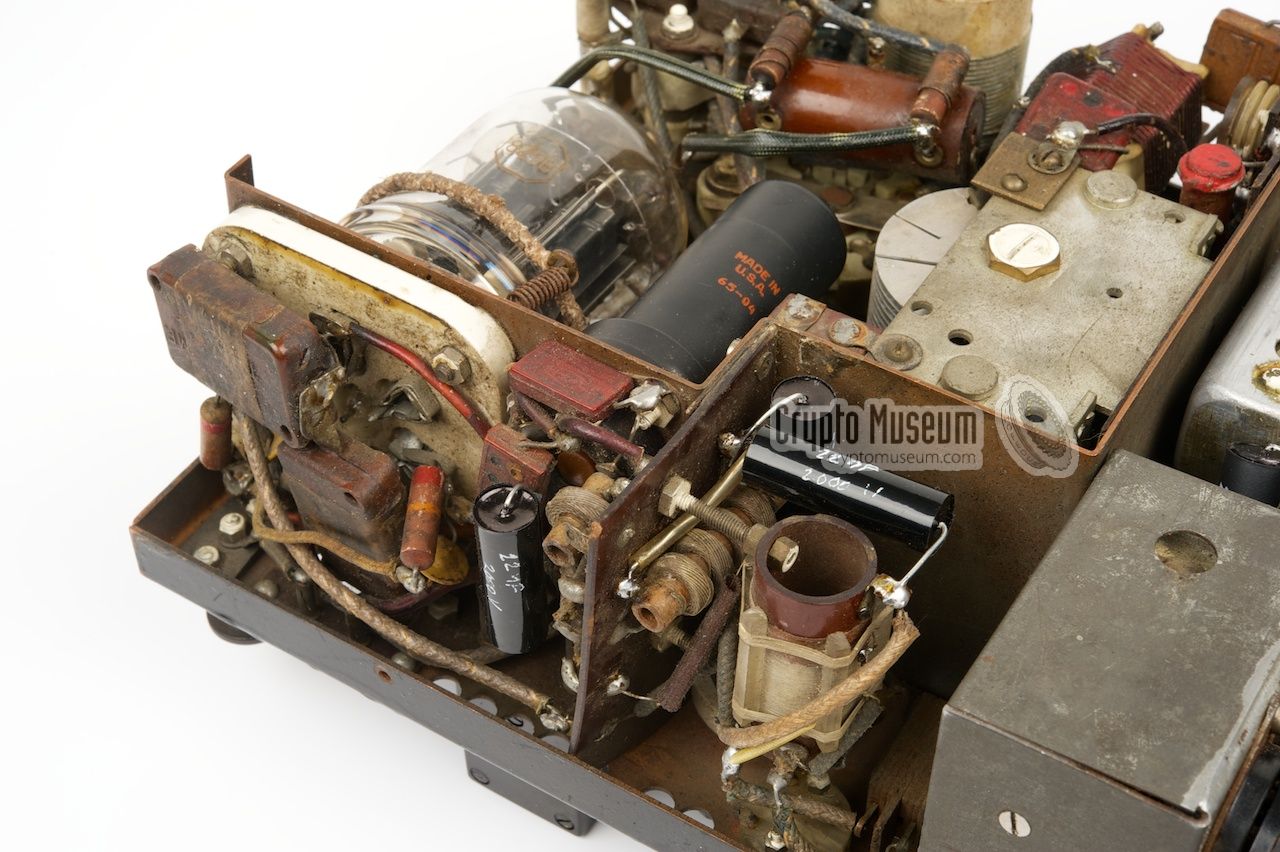
The receiver is built around four valves (tubes):
a mixer/oscillator (6K8), an IF section (6SK7), a detector/AF amplifier
(6SQ7) and finally a Beat Frequency Oscillator (BFO) combined with the
AF output stage (6SC7), the latter delivering its output at headphones level.
For AM, the BFO can be turned off with a switch at the front panel.
|
|
|
|
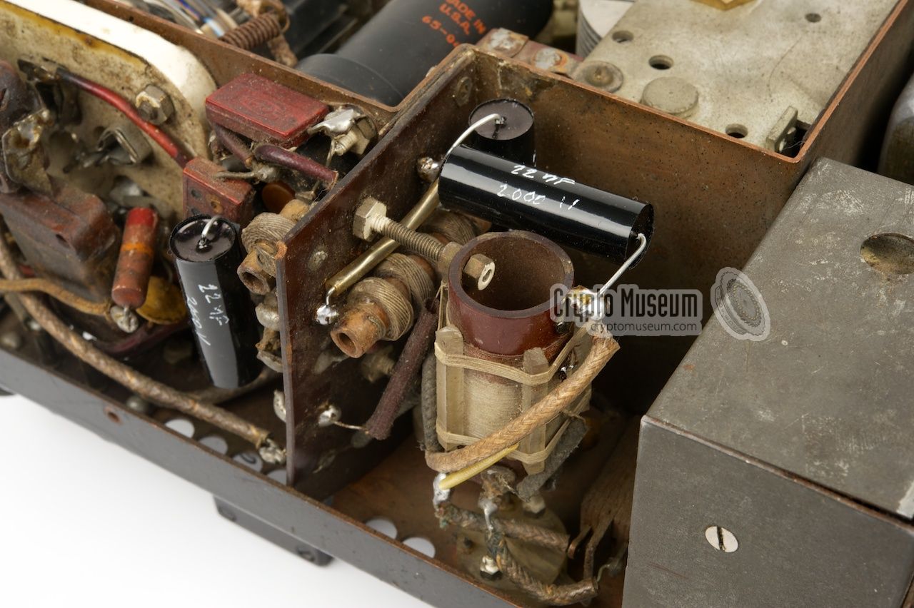
The transmitter is built around just two valves: a 6V6 for the crystal
oscillator and an 829 double tetrode for the powerful balance
power amplifier (PA). Each section has its own tuned circuit that can
be adjusted for maximum output power with controls at the front panel.
Two neon lamps and one light bulb are used as indicators for maximum power.
The transceiver is powered by 3 voltages: +500V for the transmitter,
+300V for the receiver and 12V for the filaments.
|
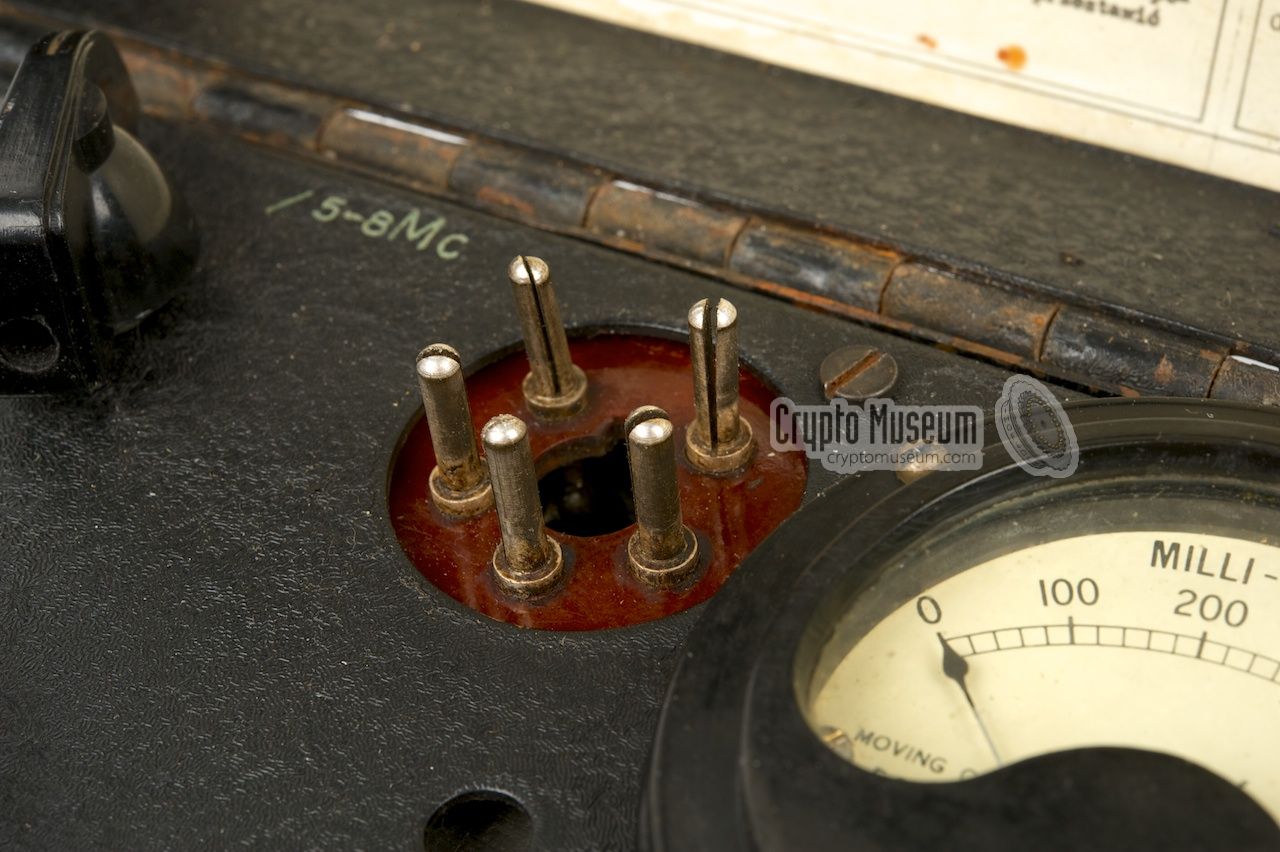
The BP-3 is powered by an external power supply unit (PSU) that supplies
12V for the filaments, +500V for the anode voltage of the transmitter,
and +300V for the anode voltage of the receiver. If the original PSU is
missing (as in the case with our BP-3), a suitable alternative with
the correct voltages should be
connected to the 5-pin socket at the top right, just left of the mA meter.
The image above shows the pin-out of the power connector when looking
into the socket at the front panel. Please note that this is mirrored
compared to the pin-out in the original circuit diagram,
which shows the solder-side of this socket.
When in doubt, check the wiring before connecting a PSU to the BP-3.
The PSU and the pin-out are the same for the BP-3, BP-4 and BP-5.
The image above shows the circuit diagram of the original valve-based PSU,
as it was supplied with the BP-4. It is identical to the PSU of the BP-3.
Below is a simplified circuit diagram of a modern replacement PSU, in which
the double rectifier valve is replaced with two semiconductor diodes.
All other values are identical the original ones. When using the replacement
PSU however, please ensure that the filaments are heated before connecting
the HT voltages (300 and 500V).
The 12V AC supply is used for the filaments of the valves. In the receiver,
the filaments of the valves are connected in pairs, so that each one gets
approx. 6V. In the transmitter, the filament of the PA valve (829) is
connected directly to the 12V rail, whilst the filament of the oscillator
valve (6V6) has a 12 ohm series resistor to bring the voltage down to 6V.
|
Inside the top lid of the BP-3 case is a paper sheet with some operating
instructions, the fully circuit diagram and a component list. In practice,
the circuit was very helpful when the had to be repaired in the field.
Below the somwehat deteriorated original circuit diagram of our BP-3.
When receiving, the PA range selector (95) has to be set to the centre
position (ODB.) so that the antenna connected
to the input of the receiver. An interesting detail is that only one side
of both neon lamps (74 and 97) is connected.
This was changed in the later BP-4 and
BP-5, probably because the limited energy made it difficult to see the
neon indicators in bright daylight.
Above: the full list of components used in the BP-3. The numbers in front
of each component correspond to the numbers next to each component in the
above circuit diagram. The component list was also part of the instruction
sheet that was mounted inside the top lid of the metal case.
|
In the early days of WWII, a group of Poles
managed to escape to the United Kingdom. Whilst the Polish
soldiers were allowed to setup and train their own Army units within the UK,
Polish engineers manned the Polish Military Wireless Unit
(Polski Wojskowy Warsztat Radiowy) in Stanmore, just north-west of London,
between Edgware and Watford. Here they maintained contact
between their government in exile and the Polish Underground Army back
in Poland.
The B-series started with the B1
and B2 in 1942, followed a year later
by the BP3,
BP4 and
BP5.
At the time of their introduction, the BP radios
were superior to the existing British spy sets, both in size and performance.
It wasn't until 1943, with the
introduction of the (much larger) British B2, that the British
were able to match the performance of the Polish sets. And with the
introduction of their A3, in 1944,
they were finally able to match the size, albeit at a lower RF power output.
➤ More about the Polish history
|
Device Spy radio transceiver Purpose Agent communication Model BP-3 Year 1943 Country UK, Poland Developer Polski Wojskowy Warsztat Radiowy in Stanmore (UK) Users Polish resistance, European resistance, SOE Successor BP-5 Frequency 2 - 8 MHz Modulation CW Antenna Long wire or dipole Dimensions 280 x 210 x 110 mm Weight 596 grams
|
Circuits Mixer/oscillator, IF, Detector/AF, AF/BFO Bands 2 (2-5 MHz and 5-8 MHz) Modulation AM (F) CW (Gr) IF 1.5 MHz Sensitivity 2µV Output 500µW into low-impedance headphones Valves 6K8, 6SK7, 6SQ7, 6SC7
|
Circuits Crystal oscillator, RF power amplifier (PA) Bands 2 (2-5 MHz and 5-8 MHz) Output 50W Modulation CW Valves 6V6, 829
|
|
|
|
Any links shown in red are currently unavailable.
If you like the information on this website, why not make a donation?
© Crypto Museum. Created: Tuesday 16 December 2014. Last changed: Wednesday, 05 November 2025 - 12:05 CET.
|
 |

|
|
|