|
|
|
|
|

|
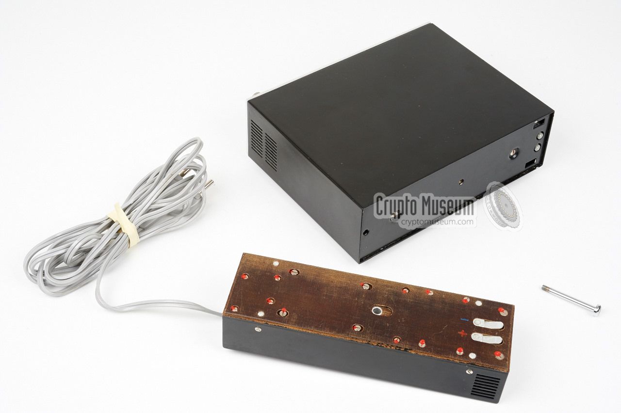
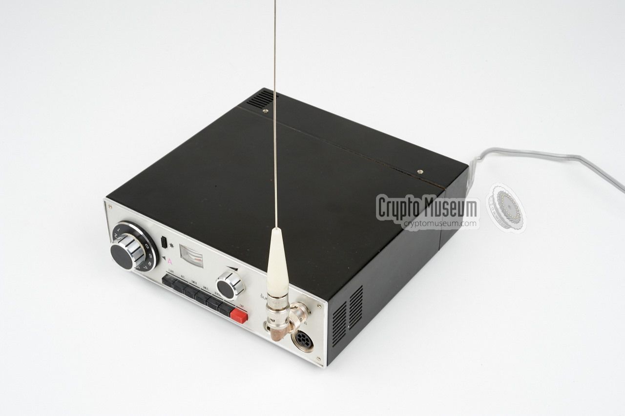
Without the PSU, the receiver measures 200 x 180 x 65 mm and weighs approx.
1 kg. All controls and connections are at the front panel, except for the
mains power, for which a fixed cable is present at the rear.
The AC mains PSU is removable. It can be swapped for a battery pack.
The receiver has a Variable Frequency Oscillator (VFO), operated with the
large dial at the left. Tuning is controlled
by varicaps, which makes it possible to use it as a scanner. Different
versions
were available, each with a specific frequency range.
The device shown here is the A-variant.
|
|
|
The covert radio bugs
that were used with Bodrog, were low-power wide-band
FM transmitters, operating on a quiet frequency that would normally
not be noticed by the average listener. The A-version
was used for receiving bugs that worked in the VHF-H band (153-165.5 MHz),
whilst the B-version was used for UHF bugs (355-383 MHz). Optionally, the
receiver could be fitted with a descrambler or a decoder, which was useful
for scrambled bugs or
subcarrier modulated bugs.
|
-
Bodrog is a river in Slovakia.
-
Správa 6 refers to Government Department 6 - Spojovacia Technika
(communication technics).
-
Správa 2 refers to Government Department 2 - Kontrarozviedka
(counter-espionage).
|
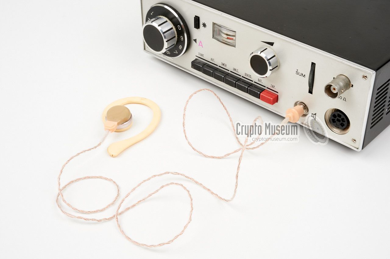
The diagram below shows the location of the various controls and connections
at the front panel of the Bodrog receiver. The antenna is connected to
the BNC socket top right. When using the supplied rod antenna,
the additonal 90° BNC adapter should be used.
A small built-in speaker is located at the right side.
An earpiece
can be connected to the 3 mm socket 1 at the bottom right.
When used, this disconnects the built-in speaker. A recorder can be connected
to the 270° DIN socket
at the bottom right. It provides the received audio, +12V power
and a start/stop contact.
The mode of operation is controlled with the six black buttons at the bottom
edge. The red button at the right, marked ZAP. (zapnuto),
is the ON/OFF switch.
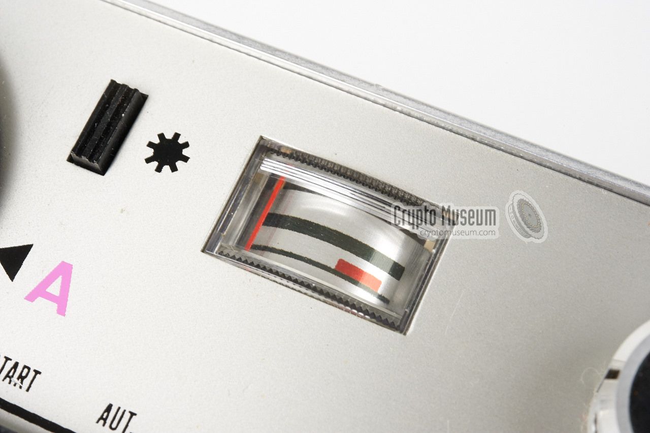
The receiver can be tuned manually, using the
dial at the left, or automatically
(scanning) by pressing the AUT. button. Scanning stops as soon as a signal
is found, and can be resumed by pressing the START button.
The meter
normally gives an indication of the frequency, with a full meter
reading corresponding to the upper edge of the frequency range. The meter
can be converted into a field-strength indicator
by pressing the SMĚR button. The battery voltage can be checked
by pressing the BATT button momentarily.
The squelch treshold is adjusted with the ŠUM knob at the top right
and can be opened continuously by pressing the UMLČ button.
On versions that have an optional decoder fitted, the DEKOD. button
is used to turn it on and off 2 (otherwise the switch is unused).
|
 |
-
Note that the earphone socket requires a 3 mm jack plug (not 2.5 or 3.5 mm).
-
It is currently unknowm whether the decoder was a descrambler
or an extra demodulator. The latter was used with bugs of which the
audio was modulated on a sub-carrier.
|
|
Different versions of the Bodrog receiver were made, each with its own specific
frequency range. The variant is indicated with a letter of the latin alphabet
(e.g. 'A') and is printed in purple on the front panel,
to the right of the tuning dial.
The following versions are currently known:
|
VHF-H 153-165.5 MHz UHF 355-383 MHz
|
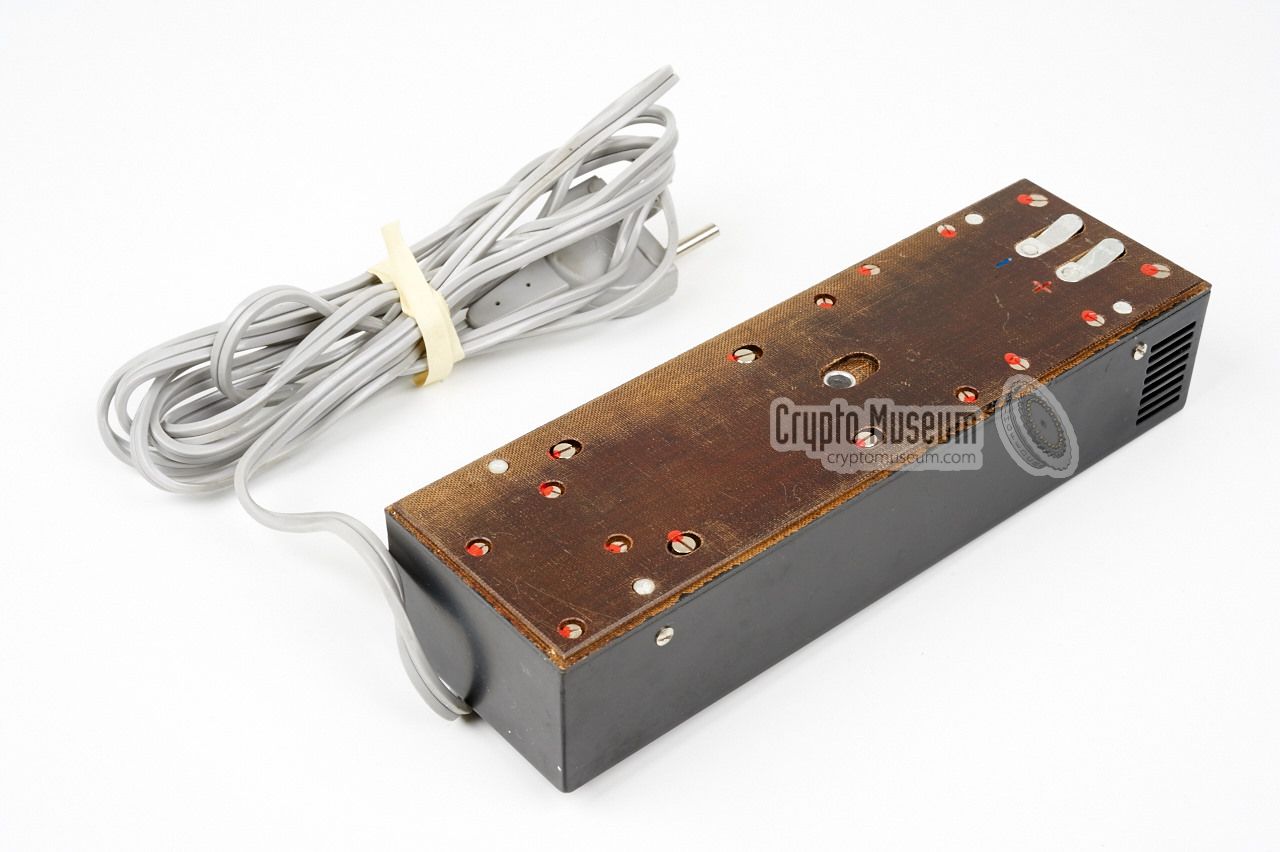
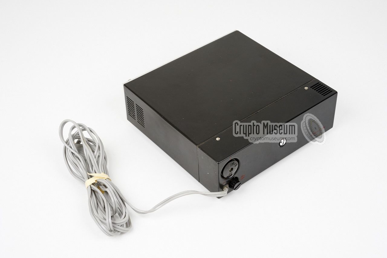
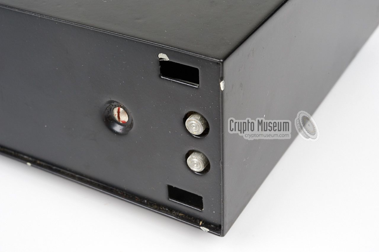
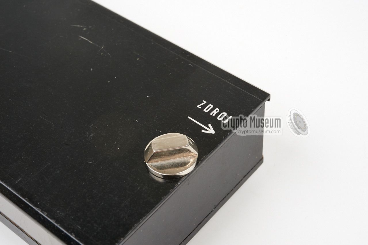
Bodrog is usually powered by a mains power supply unit (PSU) that is attached
to the rear side of the receiver by means of a large bolt at the center.
It is suitable for connection to the 120V or 220V AC mains (selectable)
that is used in most European countries.
The mains adapter has a fixed power lead with a universal 2-pin plug
at the end, suitable for most European wall sockets.
|
|
|
For mobile applications, the receiver can be powered by batteries.
For this, the mains PSU is replaced by a battery pack that has
roughly the same size.
Like the PSU,
the battery pack can be attached to the rear of the receiver.
It should be loaded with ten 1.5V AA-size cells.
When using NiCd cells (1.2V each), this produces the required
voltage of 12V DC.
|
|
|
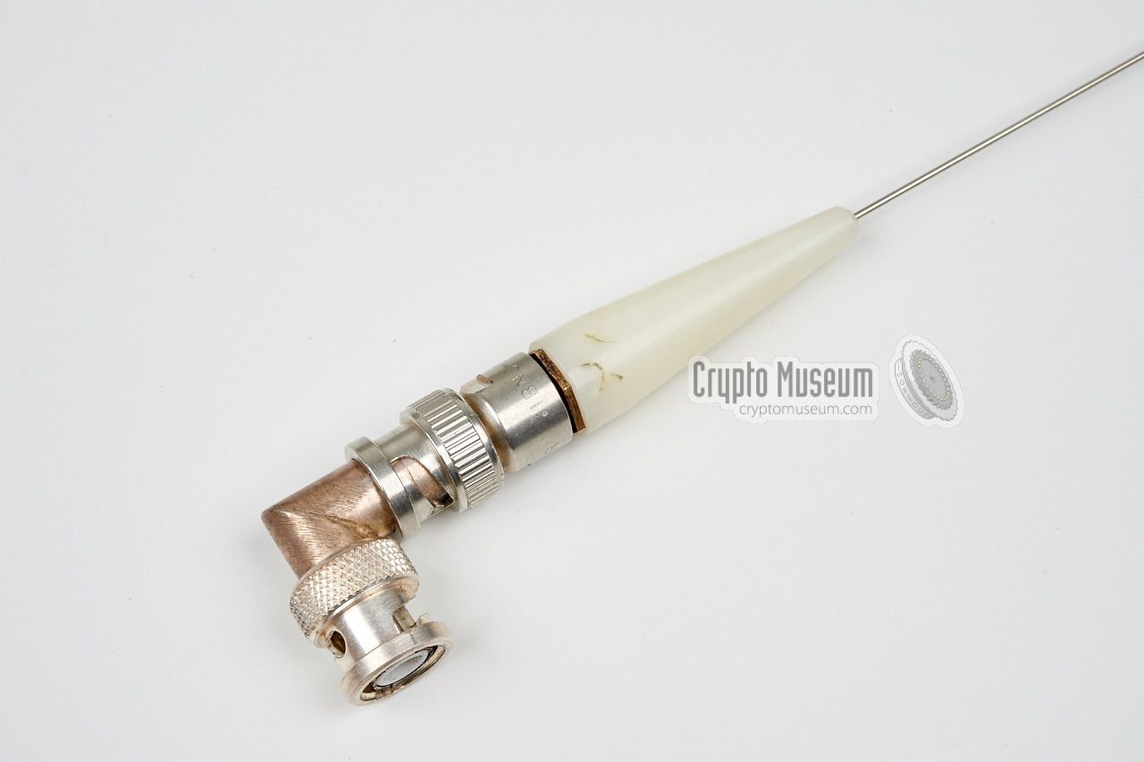
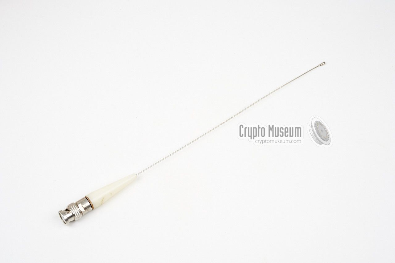
For optimum reception, Bodrog should be used with an outdoor antenna,
fitted on the roof of a building or car. If the receiver is used in
close proximity of the transmitter however, the simple rod antenna
that is supplied with the kit,
can be connected directly to the BNC socket at the front, using the
supplied 90° angle BNC adapter.
The antenna shown here is supplied with the VHF-version of the
receiver (Bodrog-A) and is 26 cm long, shorter than the required
1/4 λ length of ± 44 cm.
|
|
|
Audio is normally delivered by the small built-in speaker at the right
side of the receiver. When used in covert operations with a high chance
of detection, a standard dynamic earpiece could be connected to the
3 mm jack socket at the front.
When the earpiece is used, the built-in speaker is switched OFF.
|
|
|
A recorder can be connected to the 6-pin 270° DIN socket
at the bottom right of the frontpanel.
The audio from the receiver is available on this
connector at LINE level, plus an open collector output for starting
the recorder as soon as a signal is detected and stopping it when the
signal disappears again.
➤ Pinout of the socket
|
|
|
|
We are still looking for the operator's manual of this receiver and,
if possible, also for any technical documentation. If you have any of these
available, please contact us.
|
|
|
Below is a description of the interior of the Bodrog receiver. Please note
that the images shown below are of the Bodrog-A variant (i.e. the VHF version).
The B-version (UHF) is quite similar, but has a different type of downconverter
fitted at the right side of the device (the encapsulated area).
|
|
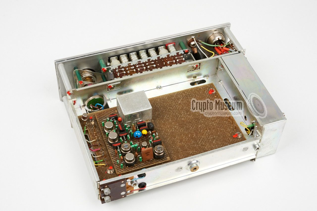
The interior of the Bodrog receiver can be accessed by
removing the PSU
(or battery pack) and then the two screws from the rear panel.
This allows the black cover to be removed towards the rear.
The unit consists of an aluminium frame with components and PCBs
at all sides, mounted to the front panel. Nearly all components
in the receiver are manufactured by the
TESLA factory.
|
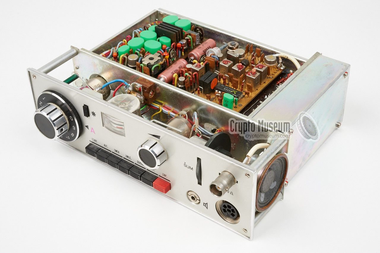
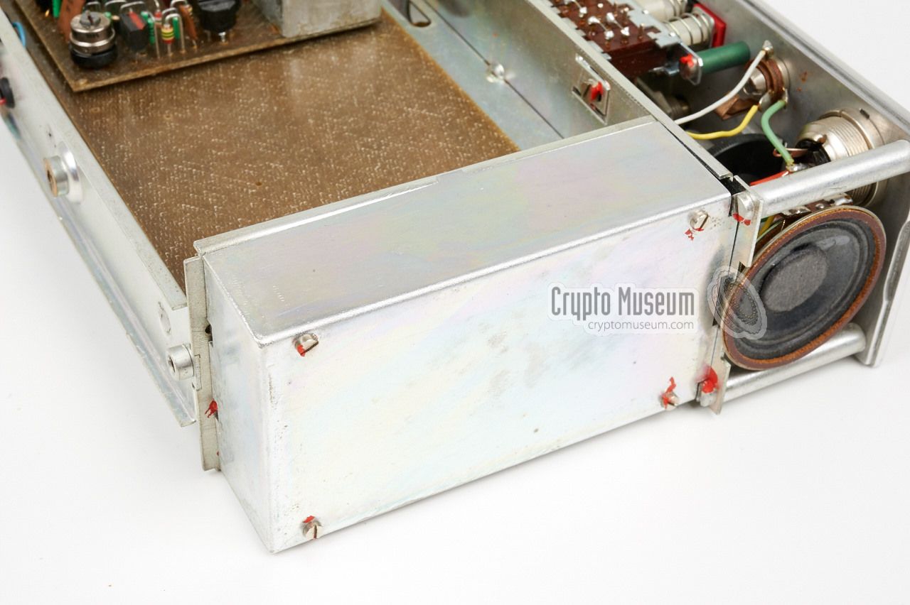
The image on the right shows the receiver as seen from the rear right corner.
At the far right are the spring-loaded contacts
for connection of the battery or the PSU. The front panel is at the left
with the speaker clearly visible at the side.
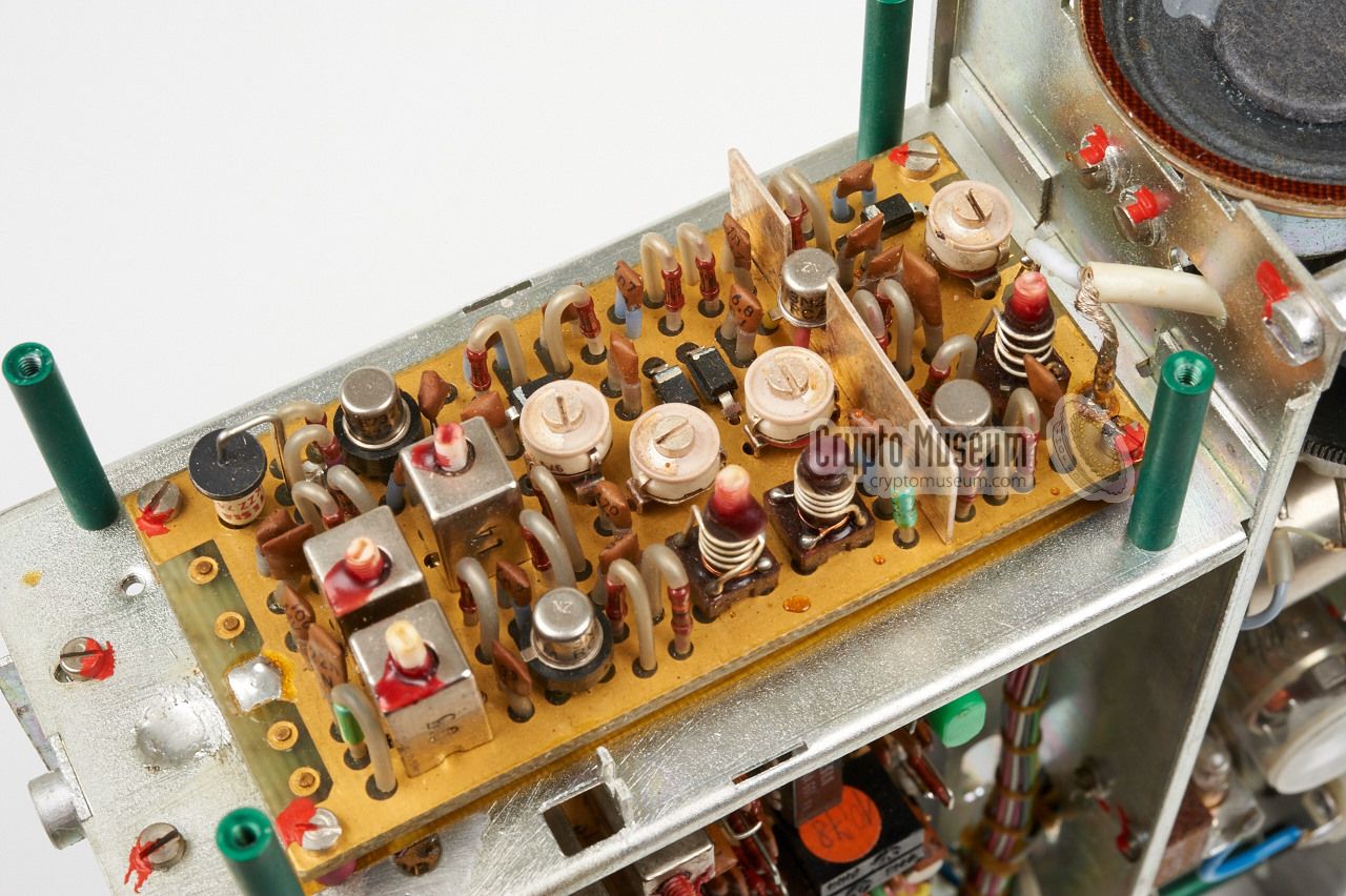
To the right of the speaker (mounted on its side)
is the VHF-H downconverter,
that is shown here with the metal shield removed.
It contains the RF pre-amplifier, the VFO and the first mixer,
all of which are varicap-controlled.
The input of the downconverter
is connected directly to the BNC socket
at the front panel via a short coax cable.
|
|
|
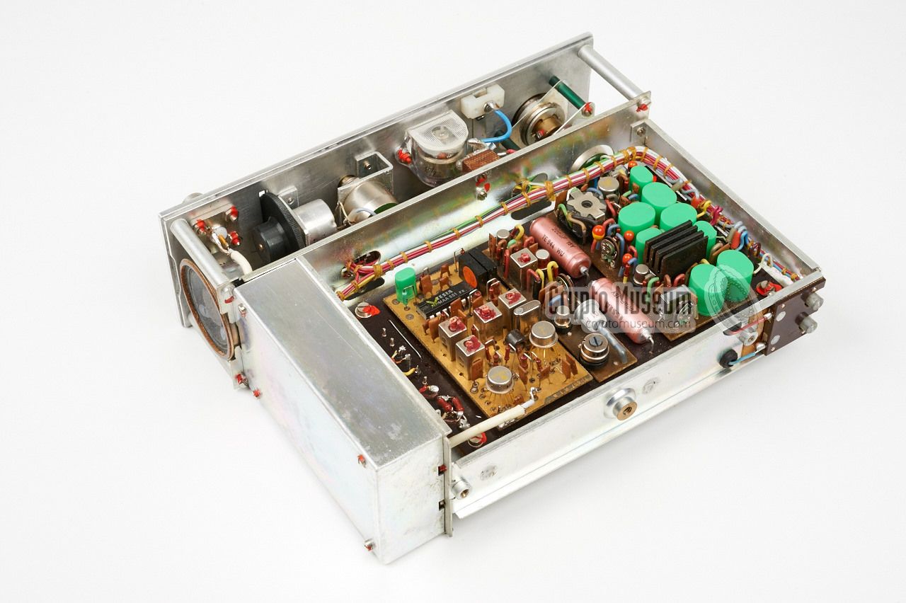
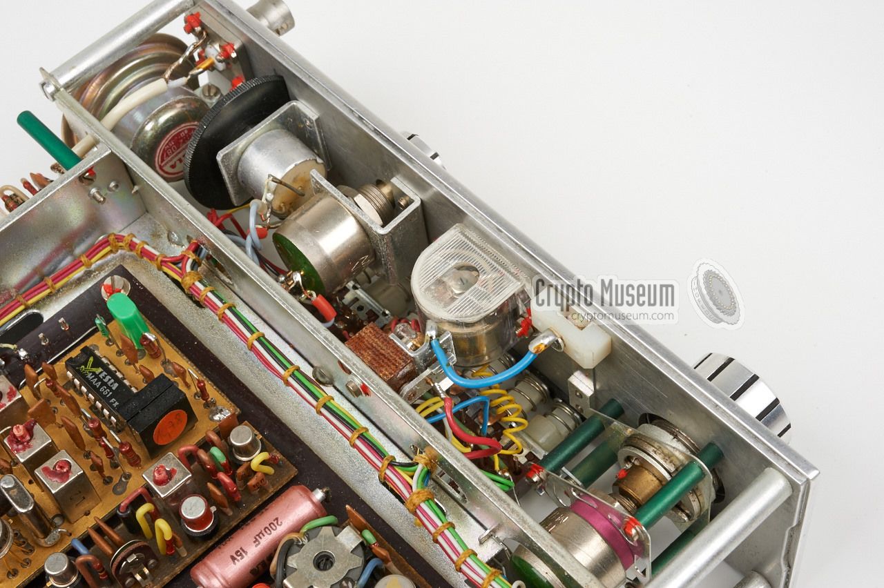
The output of the downconverter is connected to the input of the
receiver board
that is mounted directly behind it. It contains a 48.5 MHz crystal
oscillator and various mixers and amplifiers. The signal is then
demodulated by a MAA661 amplifier/demodulator made by
TESLA
[2].
At the far side, with the green capacitors, is the AF filter, squelch
control and the AF amplifier that delivers the signal to the built-in speaker.
The small circuit in the middle is probably the recorder driver.
The bottom side
of the frame holds another set of PCBs, of which the
scanner board is always present.
It controls the tuning voltage of the varicaps when scanning.
The entire frequency band is scanned in approx. 2 seconds
by applying a saw-tooth voltage to the varicaps
Scanning is stopped as soon as a signal is detected.
In the empty space aside the scanner
board the optional decoder can be fitted. This was a factory-fit
option and not a user-installable one.
|
|
The B-variant of the Bodrog receiver is built on the same chassis and has
the same controls and connections, but supports a different frequency range:
355 - 383 MHz (UHF). For this reason the Bodrog-B has a different
downconverter inside the metal enclosure at the radio's right hand side.
|
The image on the right shows the downconverter of the Bodrog-B after the
metal shield has been removed [1]. It is housed in a silver-plated
milled brass case with 10 compartments. The antenna input is at
the top left and the output is at the top (2nd compartment from the right).
In the enlargement of the image,
the varicaps are clearly visible in the lower 4 compartments.
They are used for the adjustment of the Variable Frequency Oscillator (VFO),
the pre-amplifier, the mixer and the filters. The varicaps are driven directly
by the scanner board at the bottom side.
|
|
|
Incidently, the Bodrog-B receiver shown in the above image, also has the
optional decoder board
fitted at the bottom side, next to the scanner board.
This option is used for decoding scrambled bugs
(or sub-carrier modulated bugs)
and is controlled by the DEKOD. button at the front panel.
|
The diagram below shows the simplified block diagram of the Bodrog receiver.
At the top left is the downcoverter with built-in VFO that converts the VHF
or UHF signal to 37.8 MHz. This signal is then fed into the actual receiver that
mixed it with 48.5 from a crystal oscillator, producing a 10.7 MHz wideband FM
signal which is demodulated and fed into the AF amplifier at the far right.
Note that not only the VFO, but all of the filters and the mixer of the downconverter
are varicap controlled, which means that the filters are constantly tuned whilst
tuning or scanning. This greatly improves the selectivity of the receiver.
As an option, the receiver could be fitted with a descrambler that was connected
between the demodulator and the AF amplifier. It was used for descrambling
signals from a scrambled bug. If this decoder is fitted, the DEKOD. switch
at the font panel is used to turn it ON and OFF.
It is not fitted in the Bodrog-A receiver shown here.
|
- Not connected
- Record (?)
- +12V (switched)
- Unknown (7.13V)
- Line out
- Ground
|
|
Device Surveillance receiver Purpose Reception of bugs Model Bodrog A, Bodrog B Designator TI-667 Year 1972 Country Czechoslovakia Developer Správa 6 Users Secret State Police (StB), Správa 2 (counter-intelligence) Successor Dunaj (1976) Frequency see below IF1 37.8 MHz IF2 10.7 MHz Dimensions 200 × 180 × 65 mm Weight 1 kg
|
Band VHF Frequency 153-165.5 MHz
|
Band UHF Frequency 355-383 MHz
|
|
|
|
Any links shown in red are currently unavailable.
If you like the information on this website, why not make a donation?
© Crypto Museum. Created: Thursday 20 August 2015. Last changed: Wednesday, 05 November 2025 - 12:05 CET.
|
|

|
|
|


![Bodrog-B UHF downconverter. Photograph supplied by Miro Hornik [1].](img/302197/057/full.jpg)
![Bodrog-B UHF downconverter. Photograph supplied by Miro Hornik [1].](img/302197/057/thumbnail.jpg "image # 302197/057")
![Bodrog-B with decoder board fitted. Photograph supplied by Miro Hornik [1].](img/302197/058/thumbnail.jpg "image # 302197/058")
![Bodrog-B with decoder board fitted. Photograph supplied by Miro Hornik [1].](img/302197/058/full.jpg)

