|
|
|
|
|

|
|
Poland UK WWII BP-3 →
Polish WWII spy radio set
The AP-5 was a valve-based
spy radio transceiver, developed during
WWII
by Tadeusz Heftman of the Polish Military Wireless Unit
(Polski Wojskowy Warsztat Radiowy) 1 in Stanmore
(UK)
[1].
It was introduced in 1944 and was intended for short-range
morse code communications
by SOE
agents and Resistance Organisations in occupied Poland and in
other European countries such as France.
|
The radio set is very similar to the AP-4
and it is believed that both sets are based on the earlier
A-2 2
that was introduced in 1942. The radio
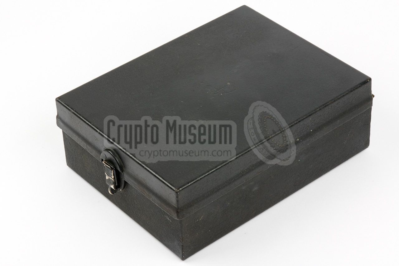
is housed in a black wrinkle paint finished
metal case with a hinged lid,
that measures 28 x 21.5 x 9.5 cm and weighs approx. 5 kg.
It covers a frequency range of 2-16 MHz – divided over 3 bands –
marked in white, yellow and red colours.
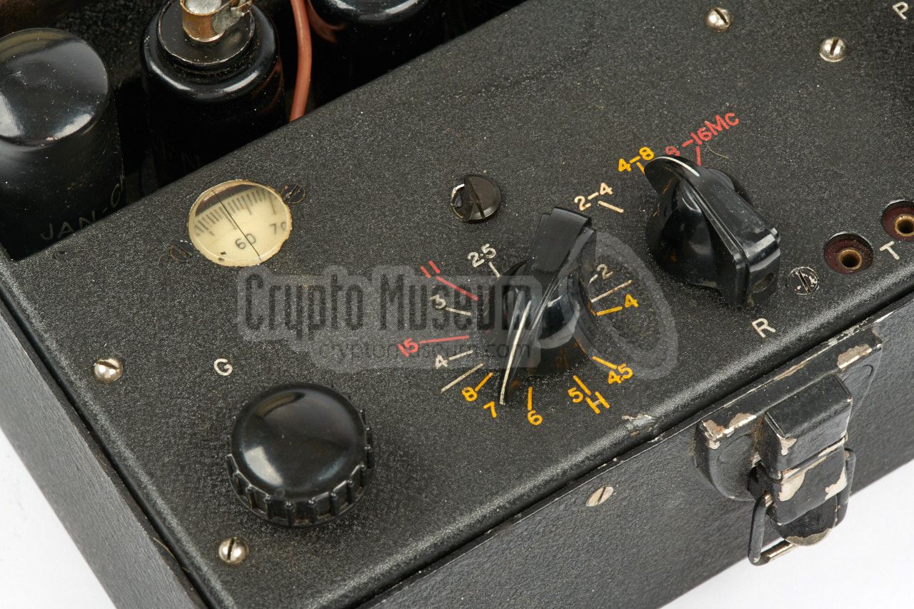
The image on the right shows a typical AP-5 set. It is built around
five valves
(tubes) that can be accessed from the control panel.
This was done to prevent overheating and to simplify repairs.
|
|
|
The radio consists of a crystal-driven transmitter, a
tunable receiver
and a mains power supply unit
that is suitable for 120 and 220V AC networks,
all mounted together behind a single front panel that can easily be
removed from the case.
Inside the top lid are the circuit diagram,
and a receiver tuning table.
Power sources should be connected to the standard octal socket.
Note that the AP-5 doesn't have a send/receive switch like its predecessors,
as it features break-in keying.
The case resembles a common toolbox of the era and was though to be
more unobtrusive than the fairly large and heavy suitcases in which the
regular British spy radio sets were housed during WWII. By using something
that resembled a toolbox, it could easily be hidden in, say, a shed.
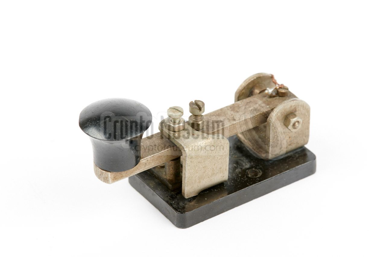
The transmitter has a buit-in morse key
and allows an external one to be
connected to the socket marked (K).
The AP-5 was introduced around the same time as the
BP-5, but has a lower
ouput power and a built-in power supply unit.
In total, 122 sets were built, but only a few were actually used
in occupied Poland. The majority was used by the British
Special Operations Executive (SOE).
|
 |
-
At the beginning of WWII, a number of Polish soldiers made their way
to England, where they were allowed to setup and train their own Army
units. Engineers who had escaped to the UK, were generally assigned to
the Polish Wireless Unit in Stanmore (near London, UK).
➤ More
-
The A-2 was introduced in 1942. Like most other Polish A-series radio sets,
it is based on the A-1 (Nelka), but has an extra IF-stage in the receiver,
as a result of which is was much more sensitive.
|
The diagram below shows the control panel of the device, which is normally
placed horizontally on the table. A suitable AC mains power source should be
connected to the octal socket at the rear edge. This socket can also
be used to connect an (optional) external power inverter.
A wire antenna and suitable counterpoise should be connected to the two
terminals at the rear right.
The receiver is located in the
front half of the device and has its
controls nicely lined up at the front edge. A linear 0-100 scale
behind a circular window provides an indication of the received frequency.
It should be used in combination with the
frequency table
in the top lid of the case. The three receiver valves and the PSU's rectifier
can be accessed directly from the control panel.
The rear half of the case contains the
power supply unit (PSU) and the
transmitter. The PSU consists of a large mains transformer (visible at the
rear left) that is suitable for 120V and 220V AC, selectable with a screw-in
voltage selector. The transmitter is crystal-driven
and consists of a single
horizontally mounted 6L6 valve
that produces an output power between 8 and 12 Watts.
The transmitter is operated with the
built-in morse key
that is located at the front right edge of the
control panel. If necessary, an external morse key can be connected to the
socket marked (K) at the right (rear) edge.
Note that there is no switch to select between transmit and
receive, as the AP-5 features break-in keying.
This means that the transmitter is activated by pressing the morse key,
and that the receiver is enabled automatically when the morse key is
released again.
|
|
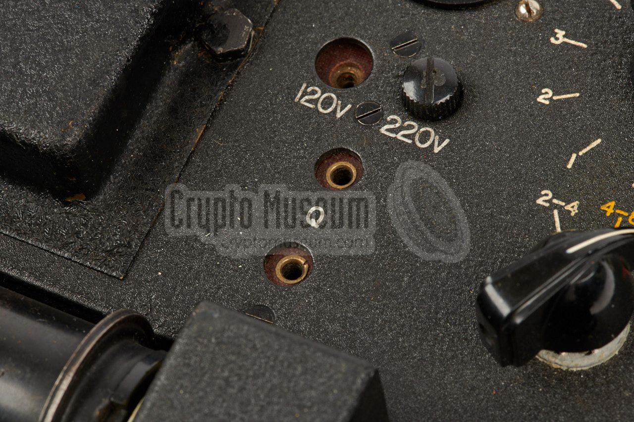
The AP-5 can be powered in three different ways:
|
- AC mains
The AP-5 can be connected directly to the AC mains network in most
countries, using the built-in power transformer. The transformer
is suitable for either 120 or 220V AC, selectable with a screw-in
terminal just below the power socket.
- 6V battery
The AP-5 can be powered from a 6V DC source, such as the battery
of a car, by using an external power inverter
or vibrator pack
between the battery and the AP-5.
The vibrator converts the 6V DC source into alternating current (AC),
which is then transformed to the desired 450V. The filaments of the
valves are connected directly to the 6V DC source.
- LT and HT batteries
In this case a 6V/20Ah battery is used for the filaments (LT), whilst
three 120 or 150V batteries are connected in series to provide
the 350-450V HT voltage.
|
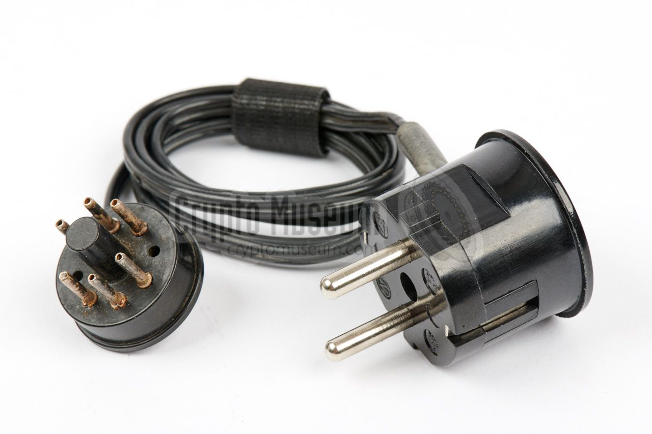
The AP-5 can be connected directly to the AC mains network,
by means of the power cable shown in the image on the right.
The AC mains is connected directly
to two pins (2 and 5) of the octal plug. Note that an extra
bridge wire should be present between pins 1 and 6.
➤ Pinout of the octal socket
|
|
|
Rather than directly from the mains network, it was also possible to
power the AP-5 from a 6V DC source, such as the battery of a car,
by using an (optional) external power inverter.
The power inverter should be connected to the same octal sockets as the
AC mains cable. Check the pinout of this socket
for the correct wiring.
No image available.
|
|
|
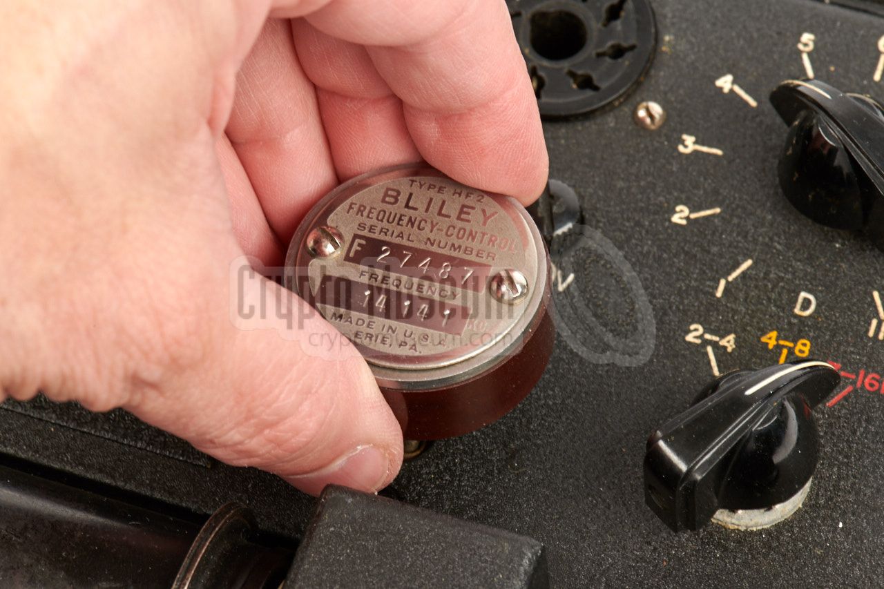
The AP-5's transmitter accepts large crystals with a pin
thickness of 2.2 mm and a distance of 19.5 mm.
This can be the well-known black rectangular crystals, or
(typically) the circular ones shown in the image on the right.
A suitable crystal should be inserted
into the socket marked (Q),
just below the mains voltage selector. The one shown here can
be left installed in the socket when the top lid is closed.
|
|
|
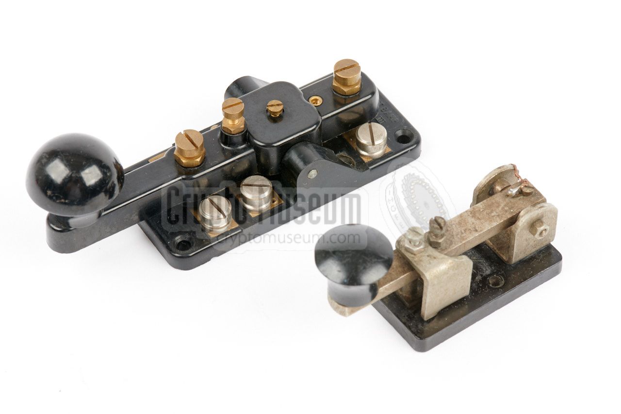
For transmissions in morse code, a high quality
built-in morse key
is available at the front right of the control panel. It can be
adjusted for the most comfortable operation.
In addition it is possible to connect an external morse key
to the terminals marked (K) towards the rear of the right side
of the control panel.
Commonly used external keys were the small ones
supplied with the British A-3
and B-2 sets (front), and the
British Morse Key No. 2 (rear).
|
|
|
|
All parts, including the complete mains power supply unit (PSU),
are mounted to the back of the control panel, which is mounted inside a black
wrinkle paint finished aluminium case, by means of four recessed 2.5 mm screws.
After removing these screws, the control panel can be extracted.
|
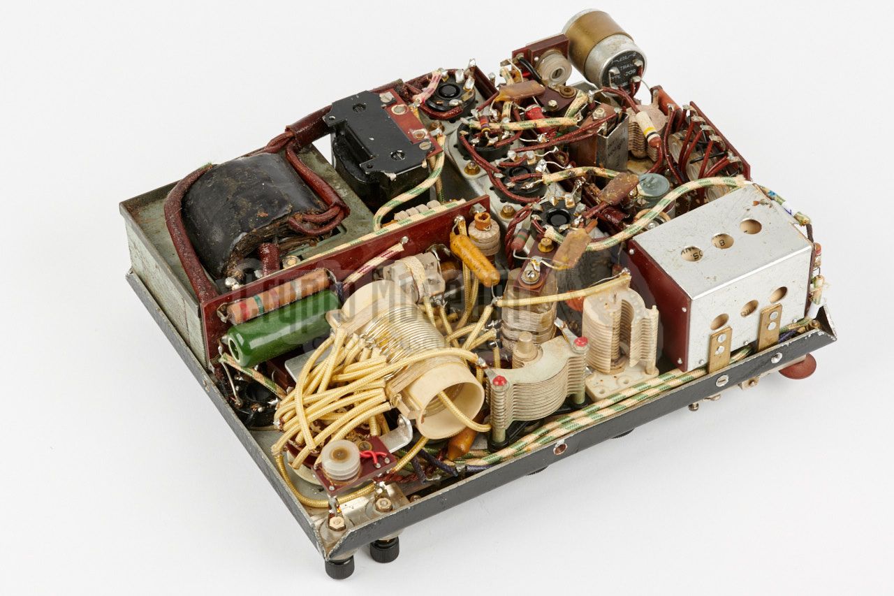
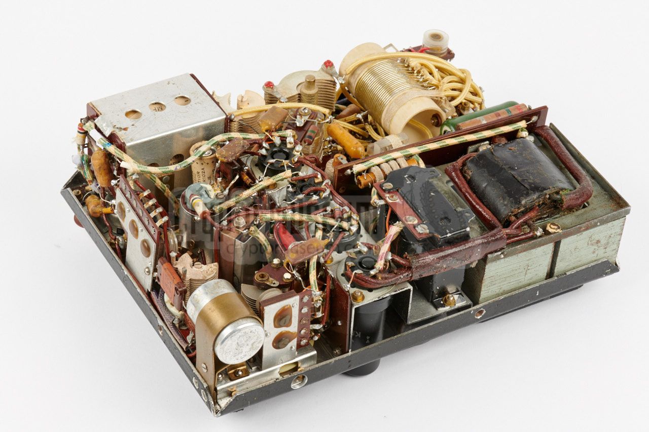
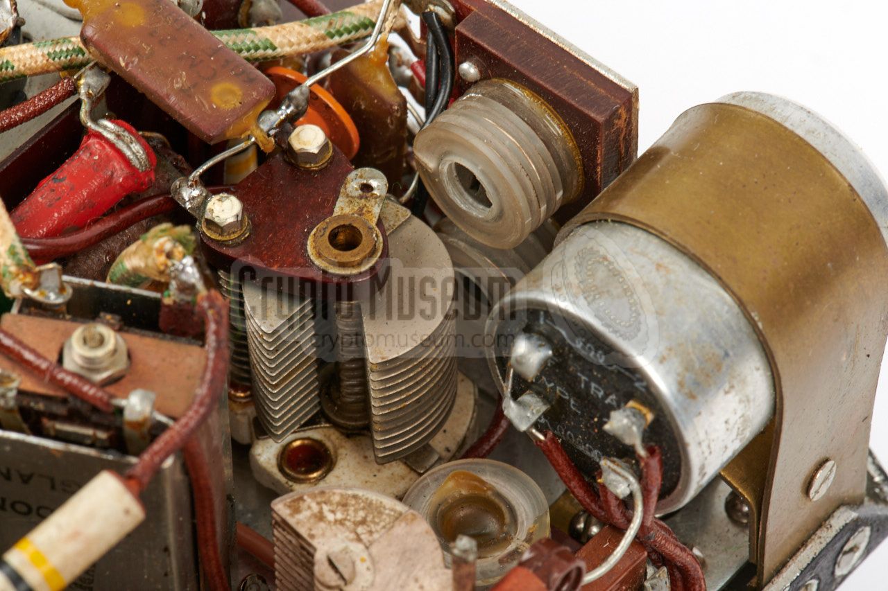
Once the control panel is extracted from the case, it can be turned over
to reveal the interior, as shown in the image on the right. The
large black mains transformer
is clearly visible in one of the corners, whilst the
antenna coil and its selector
are visible at the front of the image,
along with two large adjustable capacitors.
At the center are the solder terminals of the
sockets of the four valves
that are mounted straight up. The bright aluminium can in the rightmost corner
contains a series of capacitors that are used for stabilisation of the HT
voltage.
|
|
|
The transmitter consists of an oscillator with a
6L6 valve (tube),
which is mounted horizontally.
The 6L6 is keyed by connecting the cathode
to ground when the morse key is depressed.
An interesting feature of this radio —
that is not found on earlier models — is that it uses break-in keying.
The receiver consists of four valves:
a 6K8 that is used as the oscillator/mixer
followed by 6SJ7 IF-amplifier and finally a 6SC7 double-triode that is used
as detector and as audio amplifier.
The AP-5 transceiver is extremely well built as can be seen in the images.
Despite the fact that the unit shown here is well over 70 years old,
it is remarkable good condition.
|
|
The AP-5 can be connected directly to the AC mains, but care has to be taken
to ensure that it is
configured for the correct voltage.
The mains AC voltage
should be connected to the 8-pin octal socket at the upper edge of the
control panel. The diagram below shows the pin-out of this socket, when looking
into the socket from the top of the device. Note that this is different from
the circuit diagram (which shows the solder side of the socket). As the socket
can also be used for the connection of the DC power inverter (vibrator pack),
a wire link has to be installed in the connector (between pin 1 and 6) in order
to pass through the LT voltage for the filaments.
|
- LT in 6V
- Mains
- not connected
- HT (+) 350 to 450V
- Mains'
- LT out 6V (AC)
- Ground (LT and HT)
- not connected
|
|
|
The diagram below shows the pinout of the power socket when connecting the
device to the AC mains. Note that the wire link between pins 1 and 6 is
mandatory in order to pass the LT voltage through. Before connecting to the
mains, ensure that the correct AC voltage is selected.
|
- Interconnected with 6
- Mains
- not connected
- not connected
- Mains'
- Interconnected with 1
- not connected
- not connected
|
|
|
The diagram below shows which pins of the power socket are used when
the radio is powered from a 6V DC source, such as the battery of a car,
using the (optional) vibrator pack. The 6V from the battery is used
directly for the filaments.
|
- (+) LT 6V
- not connected
- not connected
- (+) HT 350 to 450V
- not connected
- not connected
- 0V Ground (common for LT and HT)
- not connected
|
|
|
The AP-5 can also be powered entirely from batteries (LT), in which
case a 6V/20Ah source should be used for the filaments, whilst
the 350-340V HT voltage is provided by three 120 or 150V batteries
connected in series.
|
- (+) LT 6V
- not connected
- not connected
- (+) HT 350 to 450V
- not connected
- not connected
- 0V Ground (common for LT and HT)
- not connected
|
|
1 Antenna 2 Counterpoise Q Crystal socket (quarz) T Headphones (telephone) K External morse key
|
- Shield
- Filament (LT)
- Anode
- Grid 2
- Grid 1
- pin missing
- Filament (LT)'
- Kathode, gate 3
|
|
Output power 8-12W Sensitivity 2µV Frequency range 2-16 MHz Bands see below IF frequency 1.5 MHz
|
- 2-4 MHz
- 4-8 MHz
- 8-16 MHz (transmitter: 7-16 MHz)
|
6L6 Oscillator/transmitter 6K8 Mixer/oscillator 6SJ7 IF amplifier 6SC7 Detector/AF amplifier 5Z4 Rectifier (PSU)
|
|
|
|
Any links shown in red are currently unavailable.
If you like the information on this website, why not make a donation?
© Crypto Museum. Created: Sunday 24 September 2017. Last changed: Wednesday, 05 November 2025 - 12:04 CET.
|
|

|
|
|