|
|
|
|
|

|
Short-wave spy radio transmitter
AK-20 was a short-wave spy radio station,
developed around 1975
by Mechanikai Laboratórium (ML)
in Budapest (Hungary).
The modular radio station was usually mounted inside a
briefcase and covered 2-32 MHz with an output power of 20W,
suitable for medium-range communication in Europe.
The radio set was used during the Cold War
by the Hungarian
Intelligence Agency BAS
for communication between agents and Control in Budapest,
and possibly by the Stasi as well. 1
|
The set is suitable for the transmission of high-speed
telegraphy in F1 (FSK), A1 (CW or morse code)
and A3J (SSB), with a maximum data speed of 1000 baud.
Such high-speed transmissions are generally known as
bursts, and
a cassette player is used here for playing back the data.
In addition, the set can be extended with several interfaces
and peripherals to make it suitable for the transmission of
5-level teleprinter
signals (baudot).
The image on the right
shows the basic transmitter that produces an output power
of 250 mW, shown here with a manual morse key.
|
|
|
The transmitter is powered via a connector at the rear left,
which is normally connected to the Power Amplifier (PA), which in turn
receives its power from the Mains Power Supply Unit (PSU).
The PA acts as a power hub for all modules except for the tape player.
The 250 mW output of the transmitter is connected to the PA which
increases it to 20 W, adjustable in 10 steps.
Note that the AK-20 does not contain a receiver. In practice a separate
(commercial) one was used for this.
Developement of the radio was started at the Mechanikai Laboratorium (ML)
in Budapest in 1975 with the first sets being delivered early
in 1976. The set was mainly used by the
Intelligence Agency BAS
(also known as Department III
of the Ministry of Internal Affairs),
but some sets were delivered to the
East-German Stasi,
for whom the manual was translated into German [2]. 1
It is currently unknown how many AK-20 sets were built, but it
is certain that very few have survived.
|
 |
-
It is currently unclear whether the
Stasi in East-Germany (DDR)
actually used the AK-20 in an operational context,
or that they had received only a couple of devices from the
Hungarians for evaluation.
In any case, the operator's manual was
(re)written in German by the manfacturer for this purpose,
and the device was known in the DDR under the codename Eger [4].
|
The AK-20 radio station consisted of a number of modules that were
joined together by means of cables. The modules were usually mounted
inside a briefcase as shown in the drawing below [3].
Some of the modules, such as the tape cassette player, were removable.
Furthermore, the features of the set could be enhanced by adding a
number of (optional) external peripherals.
The top section of the suitcase was used for storing additional
materials, such as the antenna wires, power cables, instructions
and frequency charts. After connecting a suitable antenna and
counterpoise (ground), the automatic antenna tuner matches the
antenna in 1 to 3 minutes.
➤ AK-20 Reference Chart
|
|
The drawing above shows the basic set of modules as they were mounted
in the lower half of a briefcase, with space at both sides for cables etc.
In addition, the set could be enhanced with some external peripherals.
The following standard modules are known:
|
- Transmitter (synthesizer and exiter)
AK-20-Lvf Linear Power Amplifier AK-20-H Antenna Tuner with Indicator (removable) AK-20-M Tape recorder/player (removable) AK-20-T Power Supply Unit (PSU)
|
AK-20-A Modulation add-on 1 ? External tape recorder (AUX) AK-20-Msp Tape recorder 1 JG-1 Telegraphy (telex) adapter (FSK) FACIT papter tape puncher/reader S/P-K Serial to Parallel interface 1 P/S-K parallel to Serial interface 1
|
-
These devices were also made by Mechanikai Laboratórium (ML)
in Budapest.
|
|
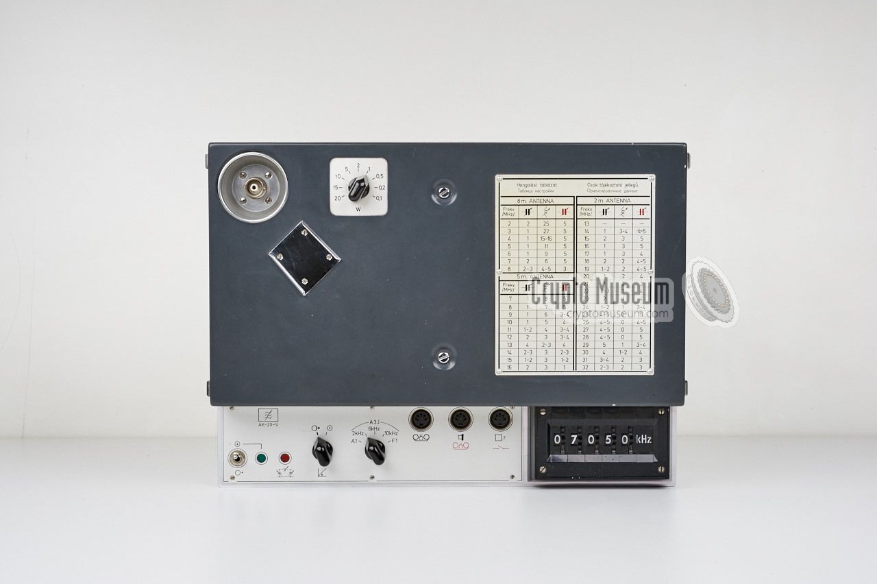
At present, the AK-20-V is the only module of the AK-20 spy radio
set in our collection. It is a combination of a synthesizer and
an exiter that produces an
output power of 250 mW, which is amplified to 20 W by the
AK-20-Lvf linear amplifier. The rotary switch, to the right of
the output socket, allows the transmission power to be adjusted
between 100 mW and 20 W in 10 steps.
|
The transmitter measures 35.5 x 26 x 8.5 cm and weight 4 kg.
Compared to other spy radio sets,
it has a rather unconventional design and looks almost
like a domestic piece of equipment,
with a row of DIN sockets at the front panel.
12V DC power is connected to a socket at the rear and is normally supplied
by the PSU via the Power Amplifier. The 250 mW output from the exiter is
available on a coxial socket at the top left/rear, which is normally
connected to the input of the Power Amplifier. It is shown here with
an adapter to the common BNC standard.
|
|
|
The transmitter is shown here with the manual morse key mounted
on the top cover. Please note that this was not always the case,
as it could be mounted elsewhere as well. The DIN sockets at the front
are for connection of the peripherals, such as the morse key and the
cassette player.
|
Although the AK-20 was generally used with a high-speed morse
burst encoder (i.e. the tape cassette player), it was also possible
to use a manual morse key in case of an emergency. For
this purpose, a small simple key was supplied with the kit,
such as the one shown here.
Note that, although the morse key shown here is brown,
the set was usually supplied with a grey one.
The key has a tapered bottom plate that can be slotted
into a tapered socket
which might be mounted on top of the device,
like on this one.
|
|
|
The diagam below shows an overview of the controls and connections
of the AK-20-V, most of which are located at the recessed front panel.
From left to right are: the DC power switch with a power indicator (green),
a tuning indicator (red), a switchable compressor/limiter, the MODE selector
(modulation) and the input sockets for tape player,
external player (aux) and morse key.
At the far right is the frequency selector that consists of five
thumb-operated digit switches. It allows the frequency to be set with an
accuracy of 1 kHz, between 2 MHz and 32 MHz. The power output of the complete
set can be controlled with the Power Selector at the top rear, between
100 mW and 20 W in 10 steps. Please note that the maximum output of the
exiter is 250 mW, but that the scale of the selector defines the output
power of the Power Amplifier (not that of the exiter).
|
|
Despite the fact that Hungary was an Eastern Block country, behind the
so-called Iron Curtain, during the time the AK-20 was developed, the
interior is surprisingly modern. It is mainly constructed with first
class components from manufacturers like Texas Instruments and KGV.
|
The image above shows the
compartimented lower half
of the unit, as seen from the bottom.
The long section at the front contains the wiring of the
front panel. Note that the device contains ICs that were mainly made
by western manufacturers like Texas Instruments and Motorola.
Some ICs are manufactured by Tesla
in Slovakia.
Note in particular the crystal filer and the quartz oscillator made
by KGV in West-Germany. It is rumoured that these components were
obtained via Austria.
|
Below is the block diagram of the extremely complex transmitter.
All frequencies are derived from a single 10 MHz reference clock
that drives three Phased Locked Loops (PLLs), each of which has
a programmable divider (÷n) that is configured with the digit
selectors at the front right of the transmitter. The other modules
are shown at the top of the diagram (with blue background).
For a full and detailed description of the above block diagram,
please refer to the German technical description [B]. The numbers in
the text correspond to the numbers above.
|
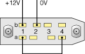
The image below shows the pinout of the 8-pin male socket at the rear
of the AK-20-V, when looking into the socket from the rear of the unit.
The pins are numbered from left to right: 1, 2, 3 and 4. The upper row
is marked 'b', whilst the lower one is marked 'a'.
+12V should be connected to pin b1. The minus terminal of the battery (0V)
goes to pin b2. Pins a1 and a4 are bridged.
|
Frequency 2-32 MHz Steps 1 kHz Deviation < 80 Hz Modulation A1, F1, Φ1, A3J Power 20 W (max)
|
|
Not much of the history of the AK-20 transmitter is currently
known and, apart from a page in Louis Meulstee's excellent book
Wireless for the Warrior - Volume 4 [2], there is no information about
this radio set in the public domain. If you have any information
about this radio, its history and/or its use, please contact us.
We are also looking for the missing parts of this station, in particular
the PSU, the PA, the Antenna Tuner and the Cassette Player.
|
- AK-20 Technical Manual
Original circuit diagrams in Hungarian and Russian.
Mechanikai Laboratórium, June 1975.
SECRET. 1
- Kurzwellensender AK-20
German translation of the operating instructions and technical description.
Mechanikai Laboratórium, date unknown. Streng geheim. 1 2
- AK-20 Reference Chart
Recreation of factory drawing 263-000000-00/02 (page 53 of the manual).
Crypto Museum, August 2018.
|
-
Manual kindly provided by Günter Fietsch [1].
-
Photograph of complete set kindly provided by Detlev Vreisleben [3].
|
- Günter Fietsch, AK-20 documentation and circuit diagrams
Received June 2015.
- Louis Meulstee, Wireless for the Warrior, volume 4
ISBN 0952063-36-0, September 2004
- Detlev Vreisleben, Photographs of complete AK-20 set in suitcase
Germany, 12 March 2005. Received August 2015.
- BStU, MfS - HA III, Nr. 9581
Date unknown. Kindly supplied by [3], September 2015.
|
|
|
|
Any links shown in red are currently unavailable.
If you like the information on this website, why not make a donation?
© Crypto Museum. Created: Friday 14 August 2015. Last changed: Tuesday, 23 July 2019 - 07:49 CET.
|
|

|
|
|


![Complete AK-20 in suitcase. Copyright Detlev Vreisleben [3].](img/302148/022/full.jpg)
![Complete AK-20 outside suitcase. Copyright Detlev Vreisleben [3].](img/302148/021/full.jpg)