|
|
|
|
|

|
|
|
Unidentified spy radio set
|
|
|
Minature valve-based spy radio set
It doesn't happen very often, but here we have a Cold War
spy radio set
of which the origin is a mystery to us. For this reason we
are asking your help in identifying it.
The set is described
in Louis Meulstee's book Wireless for the Warrier, Volume 4
as the 'French 1950s Miniature' [1],
but recent research has revealed that
it most likely is not French but probably East-European.
|
The modular radio set consists of three small identically sized
metal boxes, each of which has a top lid and measures
approx. 165 x 85 x 60 mm. A complete set consists of
three units: (1) mains power supply unit (PSU),
(2) transmitter (TX) and (3) receiver (RX).
At least two different versions of the set have so far been identified.
The image on the right shows two different versions of the transmitter
and a (modified) receiver, as they were found by Crypto Museum in Austria
in 2013. In addition, we found a more or less complete set in Bulgaria in 2022.
|
|
|
As you can see in the image above, the set came in two colours: black
wrinkle paint and green wrinkle paint.
The receiver covers a contiguous frequency range of 3.5 to 8 MHz.
On the crystal-operated transmitter, this is divided over two ranges,
marked I and II (or 3 and 6 on the later version). The only known photograph
of a complete set is this one, made by
Rudolf Staritz [2]:
The same photograph is also shown in the book
Wireless for the Warrier, Volume 4 (2004) [1].
From top to bottom it shows the PSU, the transmitter and the receiver.
The transmitter is connected to the PSU by means of 5 wires.
The receiver gets its power from the transmitter via a 3-wire cable.
Looking closely at the above photograph, it appears that the lower two
units have a black case, whils the case of the PSU is green.
Also note the two hearing aid connectors (a black and a white one)
on the front panel of the PSU. They were probably for the
Mark 2 transmitter.
Unfortunately, the origin and the current whereabouts of the above
set is unknown. For several reasons it was thought at the time that it
was made by (or for) a French intelligence agency, mainly because of
certain acccessories that were found with it, but this now seems unlikely.
|
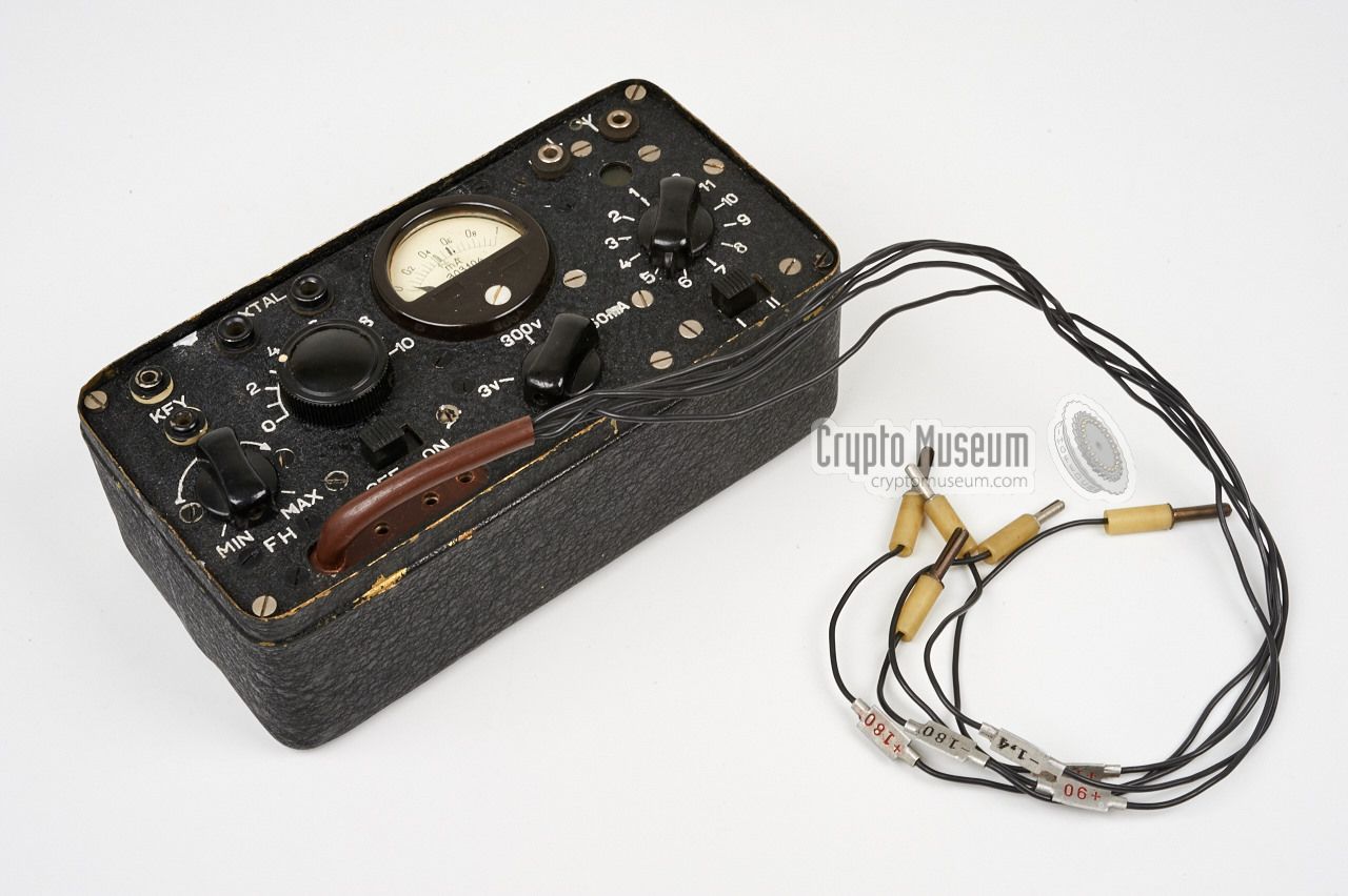
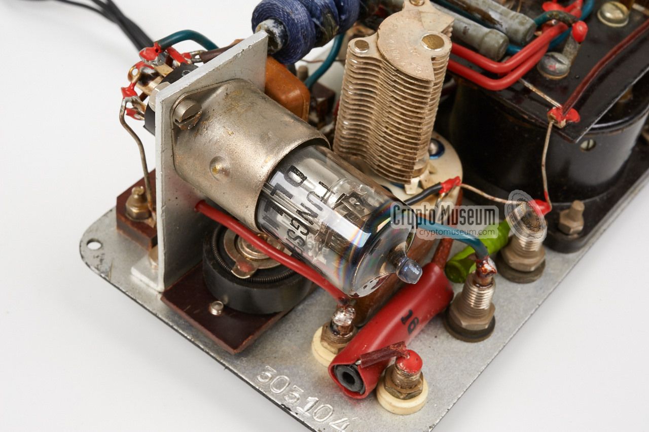
As we have identified two versions of the transmitter, we will call the
one that we think is the oldest one: Mark 1. It has banana-type connectors
for the PSU, the morse key and the receiver, and is built around a single
DLL101 valve (tube) made by Tungsram in Budapest (Hungary). It is housed
in a black wrinkle paint enclosure. Photographs of the interior
can be found below.
This transmitter has two frequency ranges, marked I and II, that are selectable
with a slide switch at the bottom right. At the bottom left is a 5-wire cable
with banana-type plugs at the end, for connection to the PSU. The
wires are labelled with the voltages:
-1.4, +1.4,
-180, +180
and +90.
|
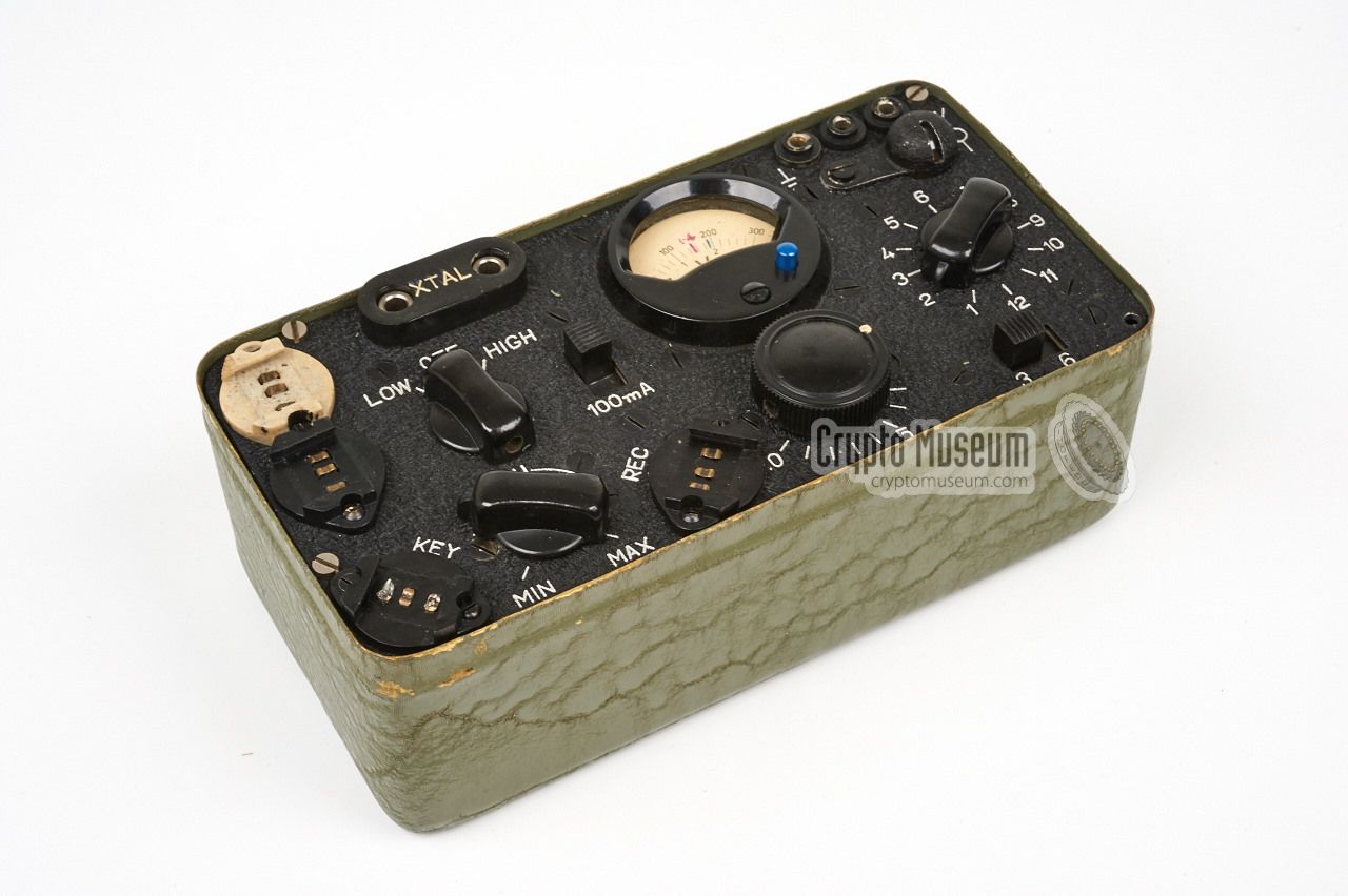
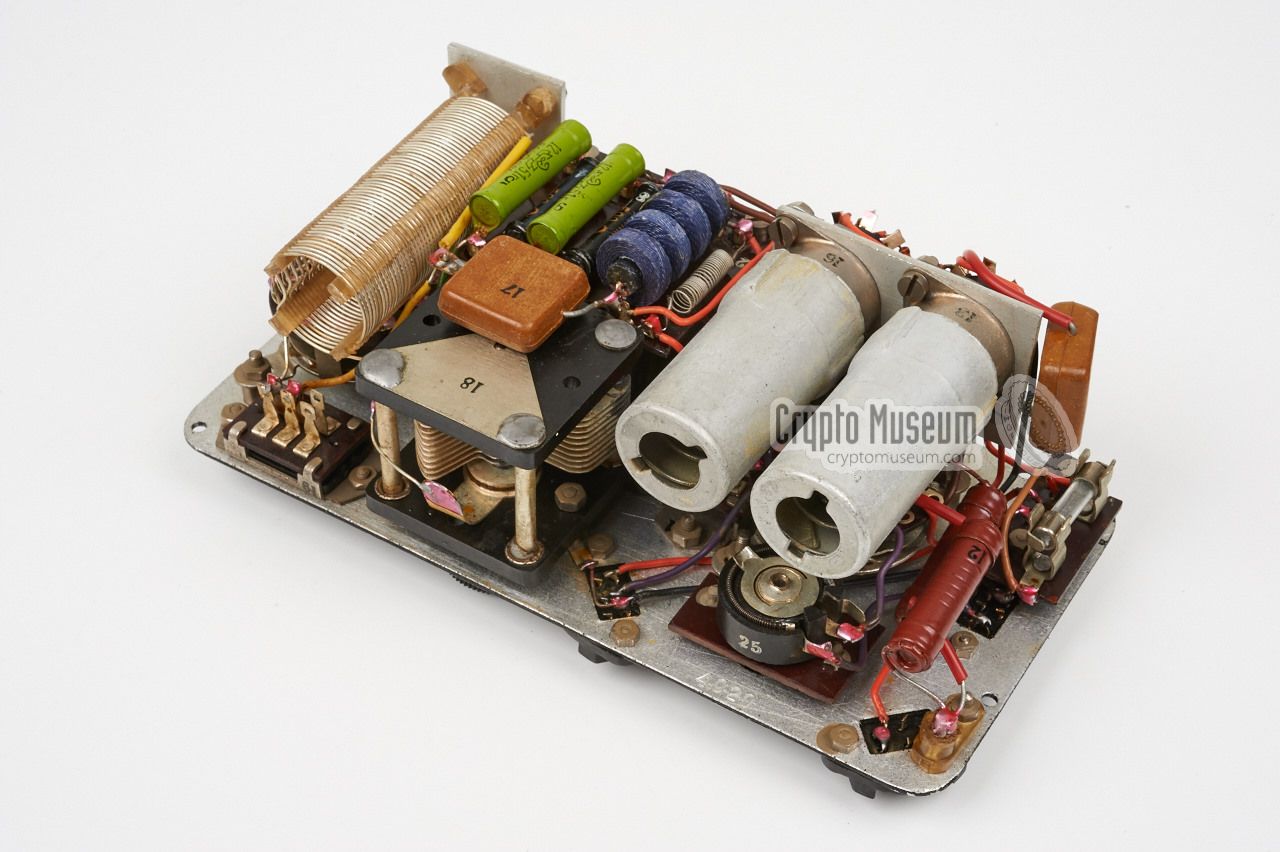
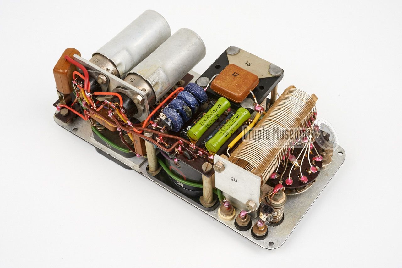
The other type of transmitter was probably made at a later date, as it is
built around two DLL101 valves. For this reason we have dubbed it Mark 2.
It is housed in a green wrinkle paint case
and uses old 3-pin
hearing aid-type sockets for connection to PSU, morse key
and receiver. This type of connector is very uncommon for spy radio sets,
but allow quick and faultless connection.
Note that the two sockets at the top left have different colours, This
was probably done to avoid mistakes when connecting the PSU, which has
two identically coloured plugs (see below). Like with the Mark 1 transmitter,
the serial number is written on the scale of the meter. Note that the
meter as well as the
tuning indicator lamp
are made in East-Germany (DDR) by VEB RFT.
Most of the parts inside the device cannot be attributed to a particular
manufacter, but it is certain that
the dark red resistors are made by
Czech manufacturer Tesla, whilst the
bright green resistors
are made by Ленинградский завод No. 130
(Leningrad Factory No. 130) in Russia.
|
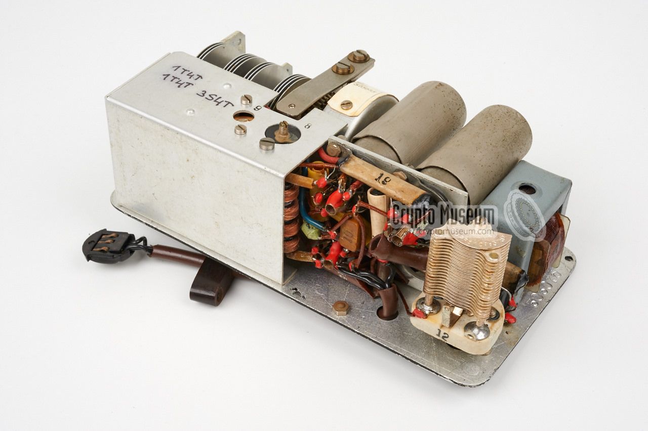
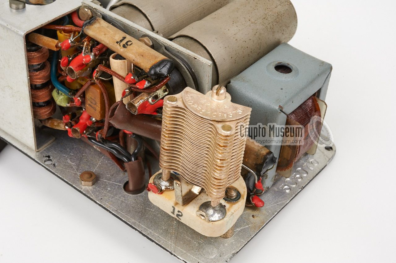
The receiver in our collection is housed in a black enclosure and has a
serial number
starting with '303', which is why we think it is the earlier
model (which we have called Mark 1). It gets its power from the transmitter
and although the receiver shown here has a 3-pin hearing aid-type plug,
the bakelite shell of the old 3-pin plug is still present. It was
modified for the Mark 2 transmitter.
The receiver is built around three miniature battery valves:
2 x 1T4T and 1 x 3S4T. It consists of an RF stage, a regenerative detector
and an AF output stage. For CW reception, the detector can be brought into
oscillation [1]. Check out the images below for details of the interior.
|
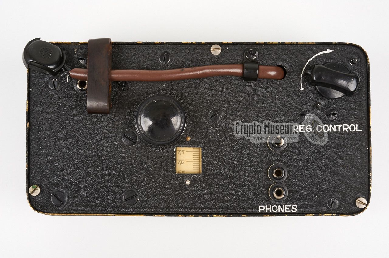
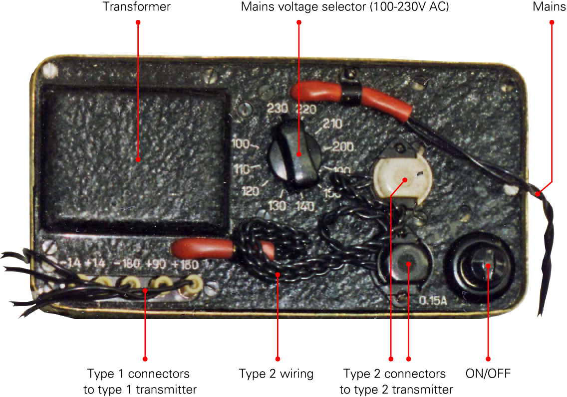
Unfortunately, we do not have an original PSU in our collection, so the
only image that we can show is the one from the complete set shown
at the top of this page. We assume that this is the later version (Mark 2)
as it appears to be housed in a green enclosure. Furthermore it has
connections for the older transmitter (Mark 1) as well as two 3-pin
hearing aid plugs
(a white one and a black one) that are probably intended for connection of
the newer transmitter (Mark 2).
The PSU is suitable for virtually any AC mains voltage in the world,
selectable between 100 and 230V in 10V steps, by means of the
rotary selector at the centre.
|
|
Each of the units has a serial number that is impressed on the inside of
the front panel. On the transmitter, it is also written at the center of
the white scale of the meter.
On the receiver it is written at the low end
of the frequency scale. The following serial numbers have been recorded:
|
| S/N | Module | Version | Case | Remark |
|
|
| 303033 | TX | 1 | Black | Photographed by Staritz [2] (complete set) |
| ? | RX | 1 | Black | Photographed by Staritz [2] (complete set) |
| ? | PSU | 1/2 | Green | Photographed by Staritz [2] (complete set) |
| ? | PSU | 1/2 | Black | Crypto Museum 1 |
| 303075 | RX | 1 | Black | Crypto Museum |
| 303077 | RX | 1 | Black | Crypto Museum 1 |
| 303104 | TX | 1 | Black | Crypto Museum |
| 4020 | TX | 2 | Green | Crypto Museum |
| 4111 | RX | 2 | Missing | Crypto Museum 1 |
| 4112 | TX | 2 | Black | Crypto Museum 1 |
|
|
It is possible that the serial numbers of the Mark 1 sets all start with '303'
and that '4' was used to identify Mark 2 sets.
Note that the Mark 1 units have a 6-digit serial number, whilst the Mark 2
units have a 4-digit number. In both cases however, the actual serial number
consists of the last three digits.
|
|
In 1992, the radio set shown in the image below was photographed,
most likely by Rudolf Staritz
in Germany [3]. The design of this radio set
is very similar to that of the individual units shown above. The same knobs
are used and the typeface of the engraved text is identical, which suggest that
it was made by the same agency.
Some of the knobs may have been swapped later in life.
|
The radio is housed in an aluminium case with leather grip, visible at the
bottom, and consists of three modules: PSU, receiver and transmitter.
At the right is a compartment for the cables.
It seems to be more advanced, and probably more powerful, than the
miniature units shown above. Receiver and transmitter each
have three frequency bands (rather than one or two).
The serial number is written on the scale of the meter of the PSU
and is probably 0619.
|
|
|
We have no information about the current whereabouts of this radio
set, but if you know someone with a similar set, please contact us,
as it might give us the possibility to investigate it further.
|
Please help us identifying this clandestine radio set, by providing as much
information as possible. If you know in which country the set was built,
by who it was used, if you have any documentation or if you know a collector
who has a similar set, please contact us.
So far we have identified components from the following countries:
|
- DDR (East-Germany)
- Czechoslovakia
- Denmark
- Hungary
- Russia (USSR)
- United Kingdom (UK)
- United States (USA)
|
- Louis Meulstee, Wireless for the Warrior, volume 4
ISBN 0952063-36-0, September 2004
- Rudolf Staritz, Photograph of complete French 1950s Miniature set
Obtained via [1], September 2015.
- Unknown author (probably Rudolf Staritz), All-in-one radio set
Obtained via Heinz Lissok. Retrieved June 2012.
|
|
|
|
Any links shown in red are currently unavailable.
If you like the information on this website, why not make a donation?
© Crypto Museum. Created: Sunday 27 September 2015. Last changed: Saturday, 14 May 2022 - 06:13 CET.
|
 |

|
|
|
|


![Photograph of complete set. Kindly supplied by Rudolf Staritz [2]. Click to enlarge.](img/cpl.jpg)


![All-in-one radio set. Click for a close-up [3].](img/single.jpg)