|
|
|
|
|

|
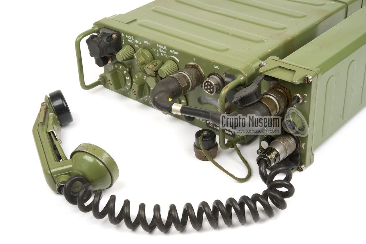
Manpack VHF-L transceiver
The RU-2 radio was a family of low-band VHF transceivers
(30-70 MHz), developed in the former Yugoslavia
in the late 1970s [1]
and built by the Rudi Čajavec factory in Banja Luka
(Bosnia and Herzegovina).
It was the successor to the RUP-12
manpack radio that was housed in the same enclosure,
and was intended for communication between infantry companies
and battalions. In practice however, the RU-2 became the 'work horse'
for the entire Yugoslav National Army (JNA).
|
The RU-2 is available in three variants.
The basic model was intended for mobile applications, soon followed
by the RU-2/1 that was available as a manpack by attaching a
battery
at the bottom and mounting it in a backpack frame.
When voice scramblers and (later) encryption devices became
available, a further model was added to the range. It had an extra
socket at the front panel for the connection of the
KzU-61 scrambler
or the KzU-63 encryption unit.
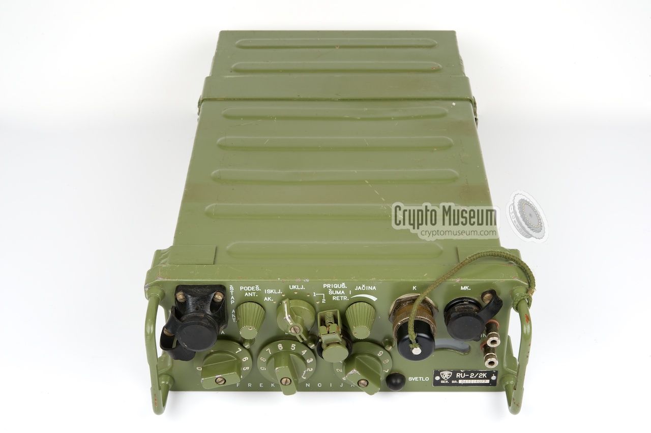
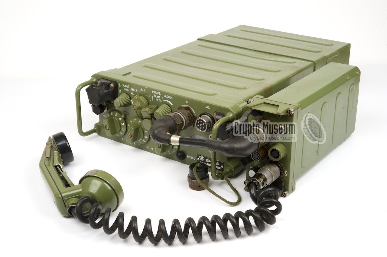
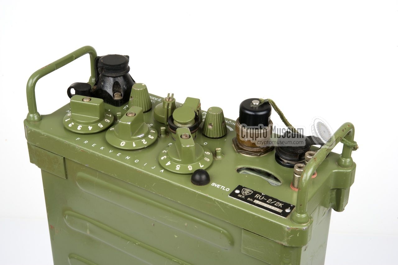
The image on the right shows the RU-2/2K, which has
a crypto socket, marked 'K', on the right.
|
|
|
In the front-end of the radio, a MOSFET-based low-noise pre-amplifier is used.
Furthermore, the radio has a sophisticated Automatic Gain Control (AGC)
and features varicap tuning. The circuits are built with transistors
and Integrated Circuits (ICs).
The intermediate frequency sections (IF) are built with ICs and use
high-quality crystal filters manufactured by the Mihailo Pupin company.
The radio offers wide-band Frequency Modulation (FM) and covers the lower
VHF frequencies from 30 to 69.95 MHz, divided over 800 channels
with a channel spacing of 50 kHz.
The desired communication channel is selected by
3 rotary switches
at the front panel (000 - 799).
In the early days, the RU-2 was sometimes
used with the American
KY-189 voice scrambler handset.
|
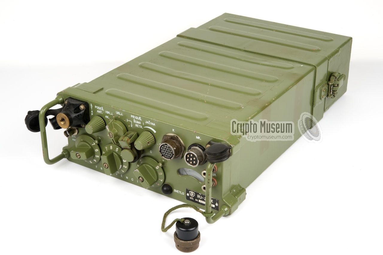
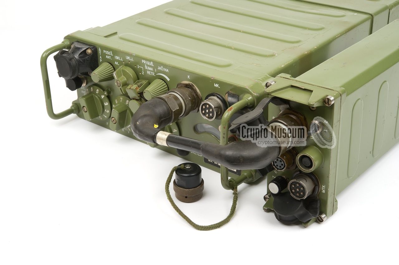
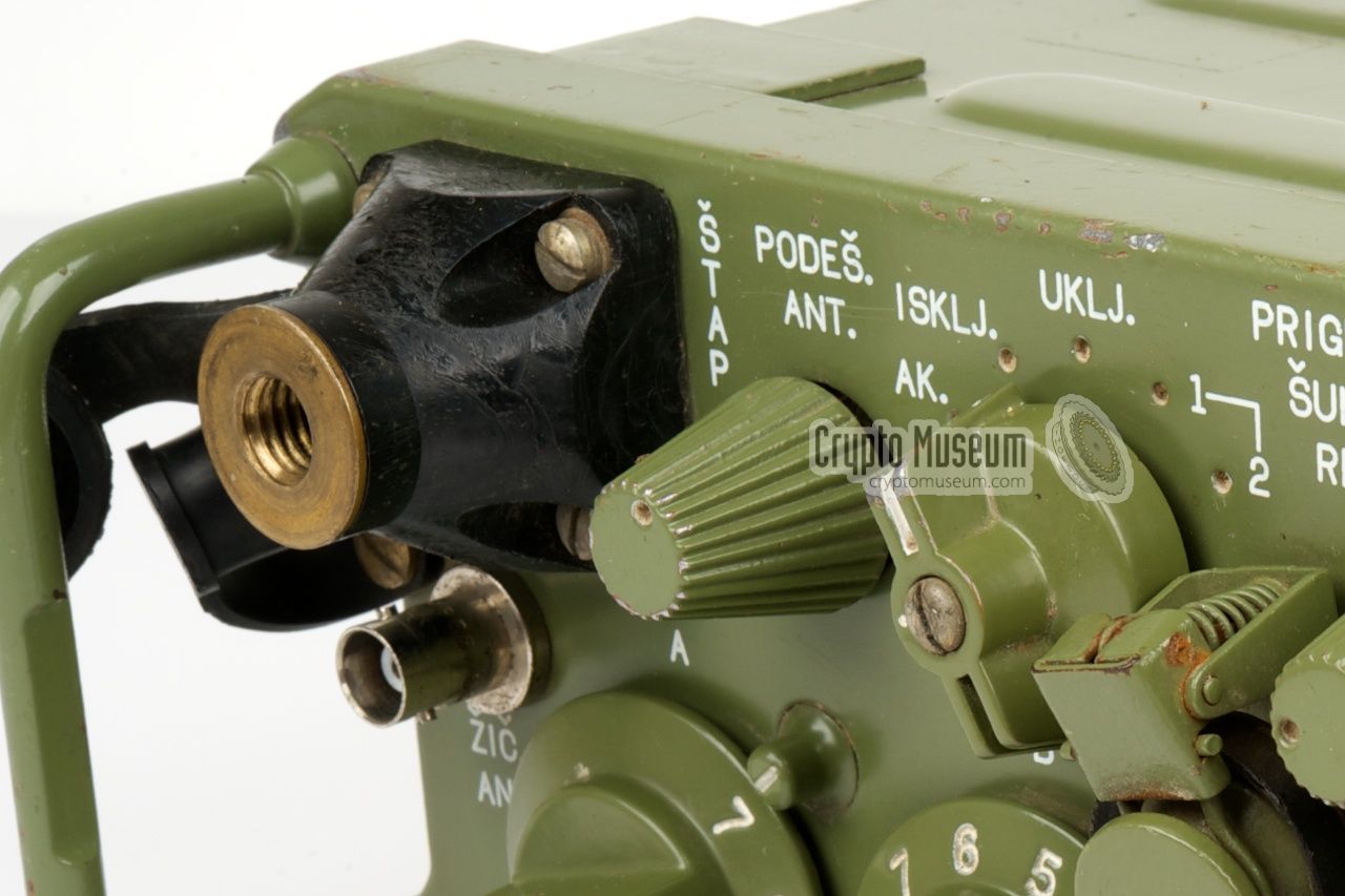
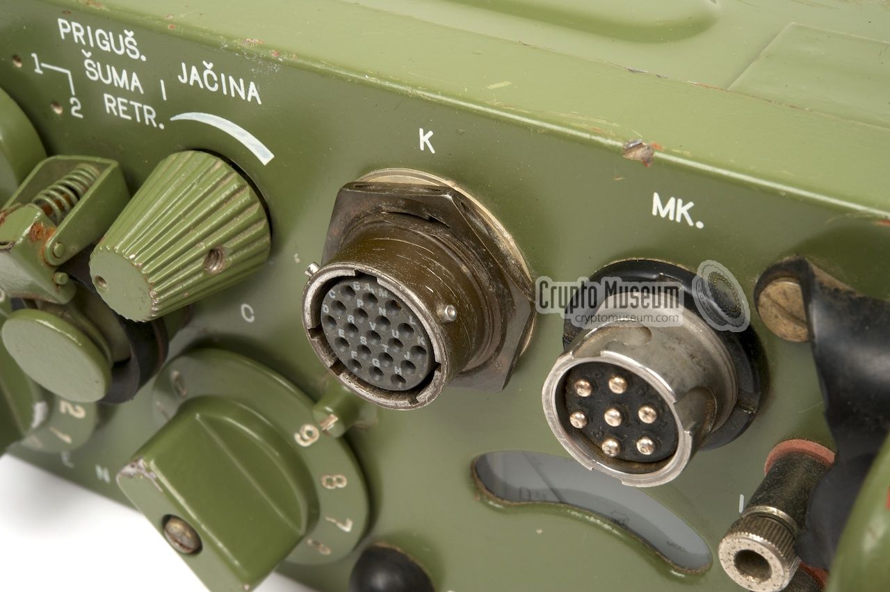
All controls and connections are at the front panel of the radio (or the
top panel if the radio is placed vertically). When used as a portable device,
a battery is connected at the bottom and the radio is usually placed in a
metal frame or in a backpack, so that it can easily be carried around.
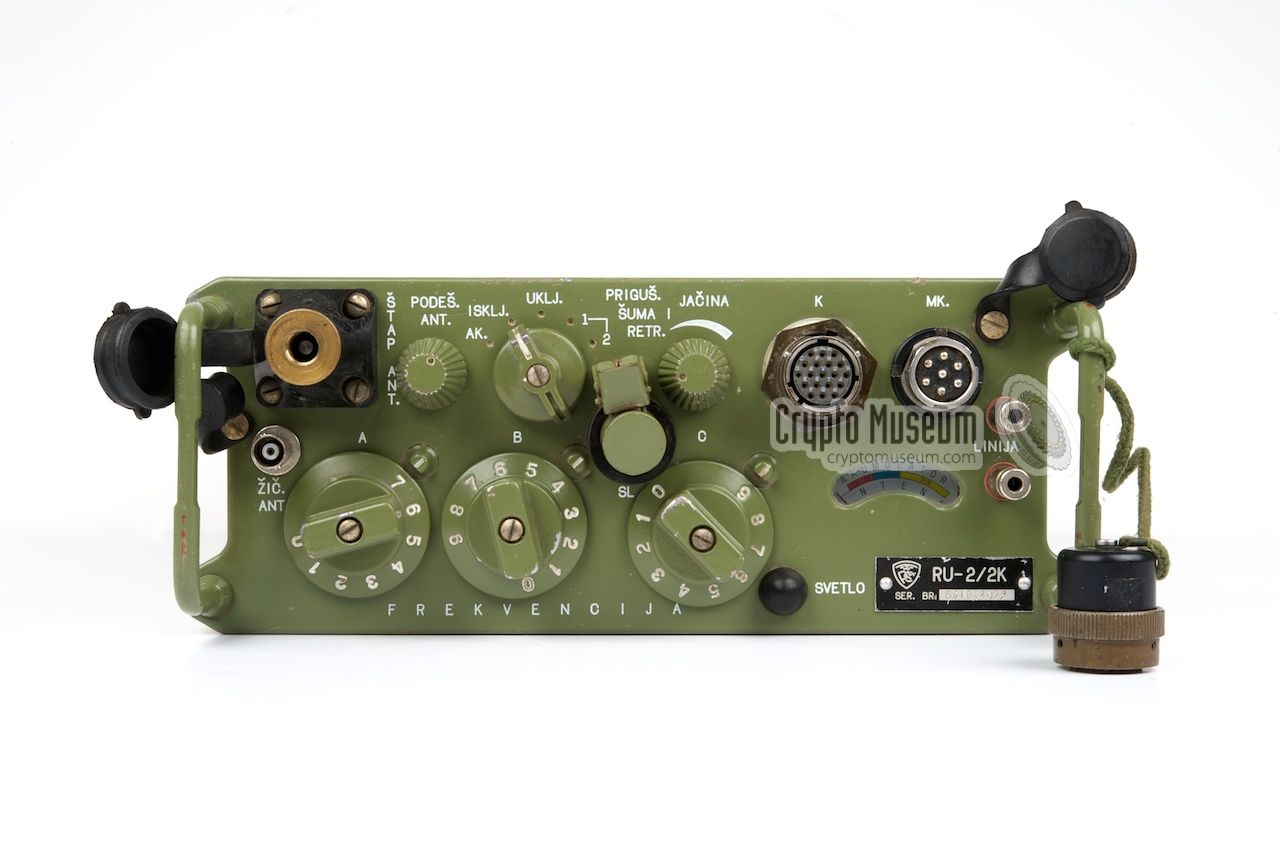
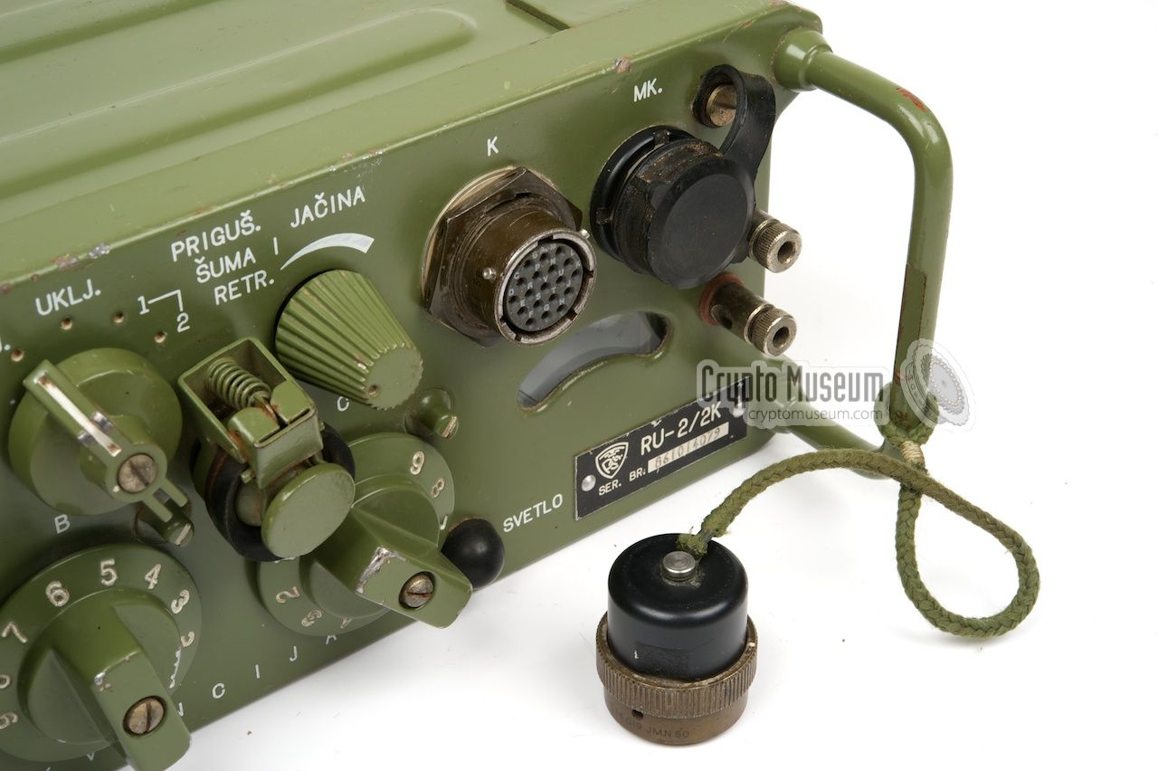
The image above show the control panel of the RU-2/2K which is slightly
different from the other models.
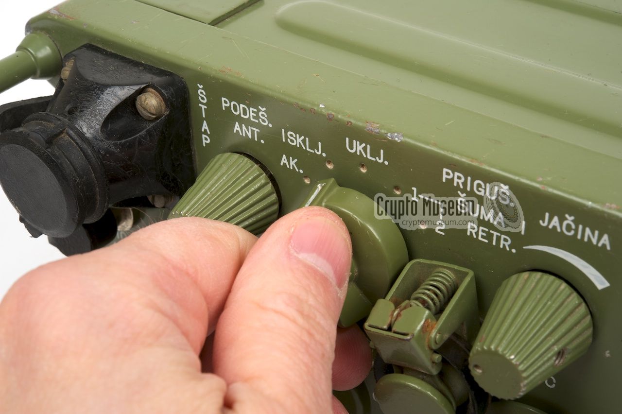
The antenna is installed or connected at
the top left, with a tuning knob to its right. The knob immediately to the
right of that is the MODE selector.
It is used for turning the set ON/OFF.
The desired frequency is selected by means of
three rotary dials that select
one of 800 channels (000-799).
A simple formula
allows conversion between channel numbers and frequencies.
At the bottom right is an indicator that is
used for tuning the antenna as wel as measuring the battery voltage.
It has three areas: empty (prazan), half-full (polupun) and full (pun).
The battery voltage can be checked by putting the MODE selector
to the AK position. A 2-wire field telephone line can be connected
at the right. At night, the meter and the channel
selectors can be illuminated.
A handset, microphone or headset is connected to the socket marked 'MK.'
at the top right. In case of the RU-2/2K, the handset might also be
connected to an external encryption device, such as the
KzU-63, in which case the
crypto device is connected to the
socket marked 'K'.
On other models of the
RU-2, this socket is not available and its place is taken by the
headphones socket,
which on the RU-2/2K is at the center of the front panel,
left of the Volume knob (Jačina).
|
|
Externally, the radio is identical to its predecessor, the
RUP-12.
It is built on the same chassis and the controls
are identical.
The internals are completely redesigned however,
with more modern components, many of which were imported from the West.
The radios were built by Rudi Čajavec in Banja Luka
and came in 3 variants, of which only one is suitable for
use with the KzU-63:
|
- RU-2
This is the basic radio that was suitable for use in base stations as
well as inside a vehicle. It is powered by a 12V DC source and produces
an RF output power of 1.4W which is rather low, considering the fact that
the chassis has sufficient space for a 5-6W PA [1].
Output power can be increased to 20W by using the external
P-25 power amplifier.
- RU-2/1
This is the manpack version of the radio. It is intended for portable use
and has a battery pack mounted to the bottom of the radio and a fixed antenna
rod at the top left. Using a handset, the radio can be used directly for
voice communication. It is normally powered by a 12V/7A DC battery that
is attached at the bottom.
- RU-2/2K
This version is nearly identical to the R-2/1 (above) but has a special
socket for the connection of an external voice protection unit, such as
the KzU-61 voice scrambler
or KzU-63 voice encryptor.
If the KzU-63 is not connected to the radio, a
dummy plug has to be
inserted into the socket marked 'K' (Kripto).
|
The image below shows the RU-2/2K, which is the only version of the RU-2
that is suitable for use with the
KzU-63.
The extra socket, needed for
connection to the KzU-63, is to the left of the handset plug.
It is shown here with a black dummy or shorting plug installed.
If the KzU-63 is not connected to the radio, this shorting plug needs to be
in place as otherwise the unfiltered audio lines of the transmitter
and the receiver are interrupted.
|
|
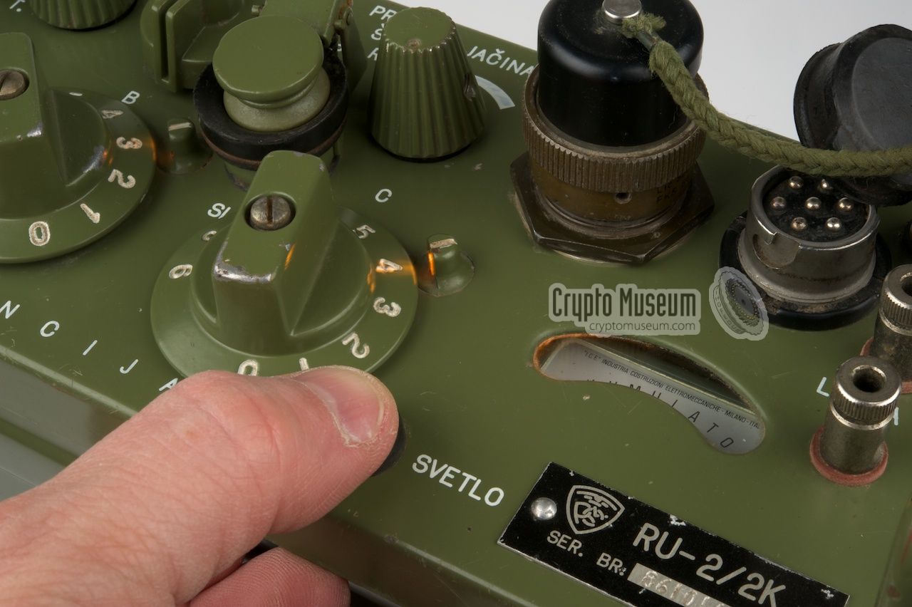
The MODE selector acts as the main power switch. It has the following settings:
|
AK. Battery check (momentary) ISKLJ. OFF UKLJ. ON (squelch open) 1 ON (squelch closed) 2 ON (squelch closed further)
|
The RU-2 is suitable for all low-band VHF frequencies between
30 and 70 MHz (actually 69.95), with a channel spacing of 50 kHz,
resulting in 800 distinct channels.
The desired frequency is selected by means of
3 rotary switches
at the front panel, between 000 and 799.
For conversion between the channel number and the actual frequency,
the following formulas can be used:
As an example, a scale setting of 367, results in
(367+600)/20 = 48.35 MHz. The lowest setting (000),
results in 30 MHz, whilst the highest setting (799) gives
69.95 MHz.
Use formula (2) to calculate backwards.
A frequency of 52 MHz,
results in a scale setting of 20 · (52-30) = 440.
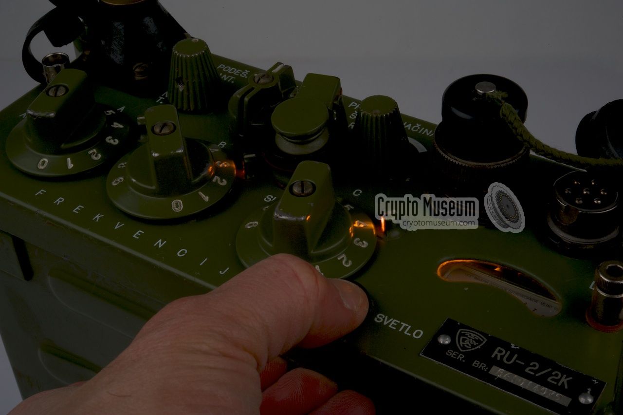
When setting up a channel, the number on the scale of the rotary
selector has to line up with a mark (a small white dash)
located at the top right of each scale. A small indicator lamp
is hidden inside each mark,
so that the radio can also be
used in the dark.
Press the black rubber button marked 'SVETLO' at the
bottom right to turn on scale illumination.
The meter is also illuminated.
|
|
A wide range of accessories was available for the RU-2, some of which
are described below. Please note that some of these accessories were optional.
|
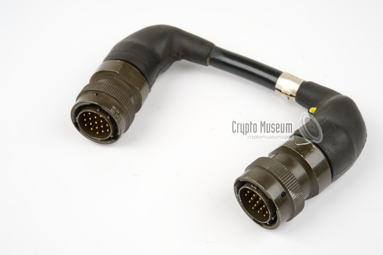
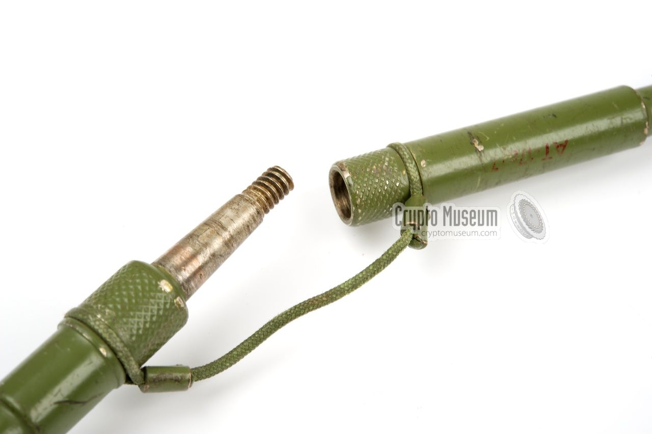
When the KzU-63 was used, it was connected to the special
Crypto socket
of the RU-2/2K (instead of the shorting plug) by means of a
short cable
that is also known as the
'dog bone'.
The handset should now be connected to the
MTK-socket on the KzU-63
instead of the MK-socket on the RU-2/2K, and the empty socket on the RU-2
should be covered by a rubber cap in order to protect it agains moist
and dirt. The image on the right shows a KzU-63 with its RUP socket
connected to the socket marked 'K' on the RU-2/2K radio via a
U-shaped cable.
|
|
|
The KzU-63 is powered directly by the RU-2/2K.
Once the encryption unit is connected to the radio, it has to be
loaded with suitable encryption keys, by means of a dedicated device.
In the image above, the KzU-63 is shown to the right of the RU-2/2K.
In practice it was installed in a side-pocket of the canvas manpack,
or strapped to the main body of the radio by means of canvas straps.
When the KzU-63 is used, the encrypted speech sounds just like (radio) noise.
➤ More about the KzU-63 speech encryptor
|
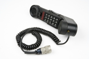
In the days before the
KzU-63 voice encryption unit
became available,
the RU-2 was sometimes used in combination with a voice scrambler,
such as the Yugoslav KzU-61, or the
American KY-189
that is shown in the image on the right.
This was also the case with the non-crypto-capable version of the RU-2
(i.e. any version other than the RU-2/2K). The KY-189 shown here was
adapted especially for the Yugoslav RUP-12
and the RU-2.
➤ More information
|
|
|
|
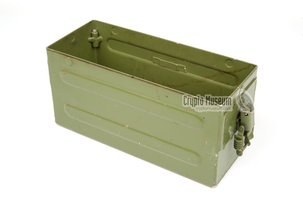
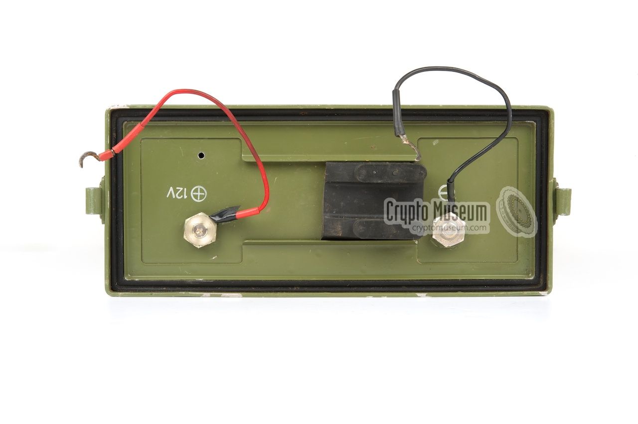
The RU-2 should be powered by a 12V DC source, such as the battery
of a car or a dedicated mains power supply unit (PSU). When used as a
manpack radio, a standard 12V Yugoslav Army battery was usually installed
in a metal box that was attached at the
bottom of the radio.
|
The image on the right shows the standard battery box that was supplied
with the RU-2. The one shown here is empty, but it normally holds 6
wet rechargeable battery cells that supply 2V each. Together they form
the BAJ-13,5 battery pack that should be connected to the wire
terminals at the bottom of the radio.
The battery is held in place by two snap-locks at the sides and is
protected against moist and dirt by a rubber gasket at the bottom of the
radio. The battery supplies 12V at 6 Ah and should be charged by an
external 13.5V DC source.
|
|
|
As an alterative to using batteries, it was also possible to use the
PT-6 DC power supply unit (PSU). It had the same form factor as the
standard battery and was fitted in its place. The PT-6 allows the RU-2
to be powered from any DC voltage between 11 and 30V, making it ideal for
installations in vehicles with 12V or 24V batteries. The PT-6
was also used with the RUP-12.
|
|
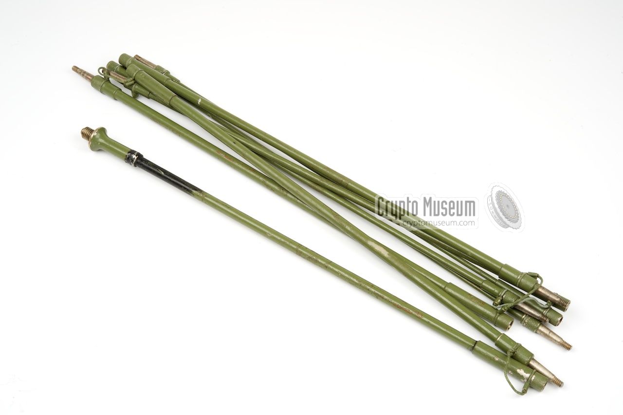
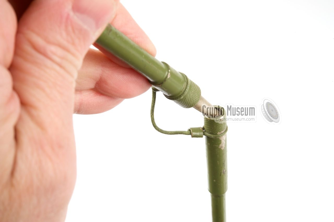
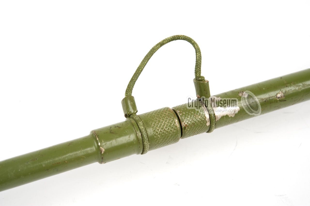
Three different types of antenna were available for the RU-2. These are the
same types as for the earlier RUP-12 radio. When
delivered, the radio came with a standard AT-17 long rod antenna. It consists
of 8 short pieces that are held together by short straps.
When assembled,
the antenna is approx 311 cm long and should be
installed in the black socket
at the top left of the front panel.
|
As an alternative to the long rod,
a short flexible variant
(AT-19) was available. It is 112 cm long and is also mounted on the black
antenna base at the top left. Although its performance is much worse than
that of the long rod, it is often more practicle in combat situations. The
lower 20 cm of the antenna are flexible, so that it can be erected whilst
the operator lies on the ground.
If the operational conditions are suitable and performance is mandatory,
A long wire antenna of up to 50 metres can be connected to the BNC socket
marked ŽIČ at the left edge of the front.
|
|
|
When using a wire antenna, a suitable BALUN should be used in order to
match the antenna to the 50 ohm impedance of the transceiver. The standard
KS-28 wire antenna included a suitable BALUN.
The ŽIČ-socket can also be used for any other suitable antenna
with a 50 ohm load. In any case, the antenna tuning knob (PODEŠ. ANT)
had to be adjusted during transmission for a maximum reading of the
antenna indicator (meter) at the bottom right.
|
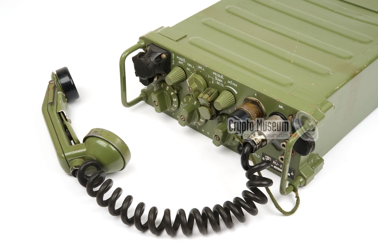
The socket marked 'MK.'
at the top right of the control panel is for the
connection of the audio ancillaries, such as the standard handset shown
here. It consists of a metal assembly with a microphone and a speaker,
much like the handset of an ordinary telephone set, with a
Push-To-Talk (PTT) switch in the middle.
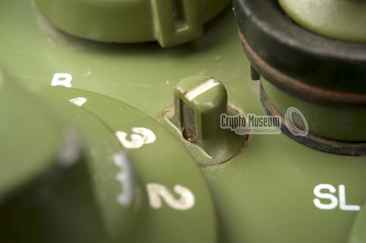
The MK-socket can also be used connecting a headset or a single
microphone. In the latter case, a standard pair of headphones should be
connected to the SL-socket
at the center of the front panel. 1
|
|
|
-
On the RU-2/2K featured here, the SL-socket is at the center of the front
panel. On all other models, it is at the top right, to the left of the
MK-socket, in place of the K-socket.
|
The block diagram of the RU-2 is nearly identical to that of the
earlier RUP-12 transceiver.
The image below shows a simplified block diagram of the RUP-12,
and is based on several more detailed block diagrams from the
operator's manual [3]. The transceiver parts (TX) are at the top,
whilst lower half contains the various stages of the receiver.
The audio frequency stages (AF) are at the bottom right. The receiver is
a straightforward heterodyne with a 1st IF frequency of 10.7 MHz.
Some parts of the 10.7 MHz section of the receiver are shared with
the transmitter (AFC).
The transmitter section is shown at the top. The modulator
at the right mixes the audio signal from the microphone with a
10.7 MHz signal from a crystal oscillator. The advantage of using
10.7 MHz is that the crystal reference of the receiver can also be used
for selecting the desired transmission frequency.
The most complex part of the transceiver is the crystal reference itself:
The block diagram above shows how the crystal reference is synthesized.
The digital parts are in the grey box at the top left.
The three crystal-based parts that determine the actual frequency are
at the bottom, shown in red.
The leftmost one is a 5 MHz crystal oscillator with a configurable
(4-step) multiplier behind it. It allows the 5 MHz signal
to be multiplied by 1, 2, 3 or 4. This signal is fed to the first
mixer, where it produces a sum and a difference signal. If we also
take 0 MHz into account (i.e. multiply by 0, which means no signal),
the following 8 steps are possible:
-20, -15, -10, -5, 0, 5, 10, 15 MHz
These steps are controlled by the leftmost frequency selector on the
front panel of the transceiver (0-7). The other two digits are
determined by two crystal banks with 10 crystals each (0-9). The first
one is added in the second mixer, whilst the third one is fed into
a phase discriminator and a differential amplifier followed by a
complex logic circuit that is finally mixed at the heterodyne.
|
The drawing below shows the wiring of the
7-pin socket marked 'MK.'
at the top right.
It is used for the connection of a handset, headset or another
microphone/speaker combination. The colours are of the internal wiring
when looking into the socket from the front panel of the device.
Connector MK - Handset
The drawing below shows the identification of the pins of the
socket marked 'K' (Kripto).
It is used for connection to the RU-2/2K radio set and
provides access to the unfiltered audio signals of the transmitter
and the receiver. It also supplied 12V DC to the KzU-63.
Wiring currently unknown.
Connector K - Crypto Unit
|
|
|
|
Any links shown in red are currently unavailable.
If you like the information on this website, why not make a donation?
© Crypto Museum. Created: Saturday 18 April 2015. Last changed: Tuesday, 28 September 2021 - 06:33 CET.
|
 |

|
|
|


