|
|
|
|
|

|
|
Monitoring Telefunken
Panoramic display unit
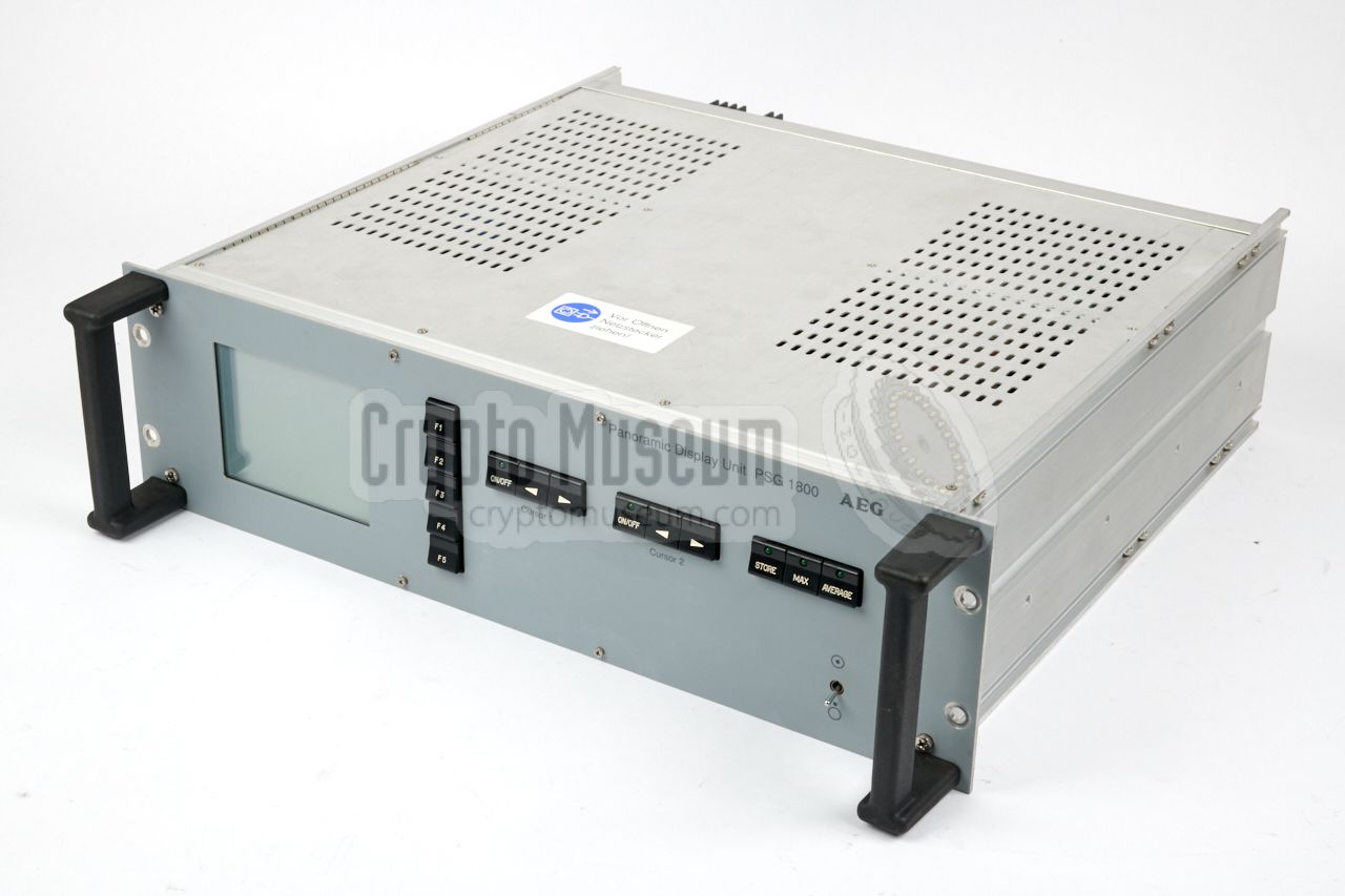
PSG-1800 is a panoramic display unit
(German: Panorama Sicht-Gerät), sold
from the late 1980s by AEG-Telefunken 1
in Ulm (Germany).
The device was largely developed by ELCOM
in München (Germany)
and was intended as an accessory for
the E-1800/x
and E-1900/x
series of receivers.
|
The device is housed in a 19" 3U rackmountable case that has the same
look and feel as the front panel of the
E-1800 HF receiver and the
E-1900 VHF/UHF receiver.
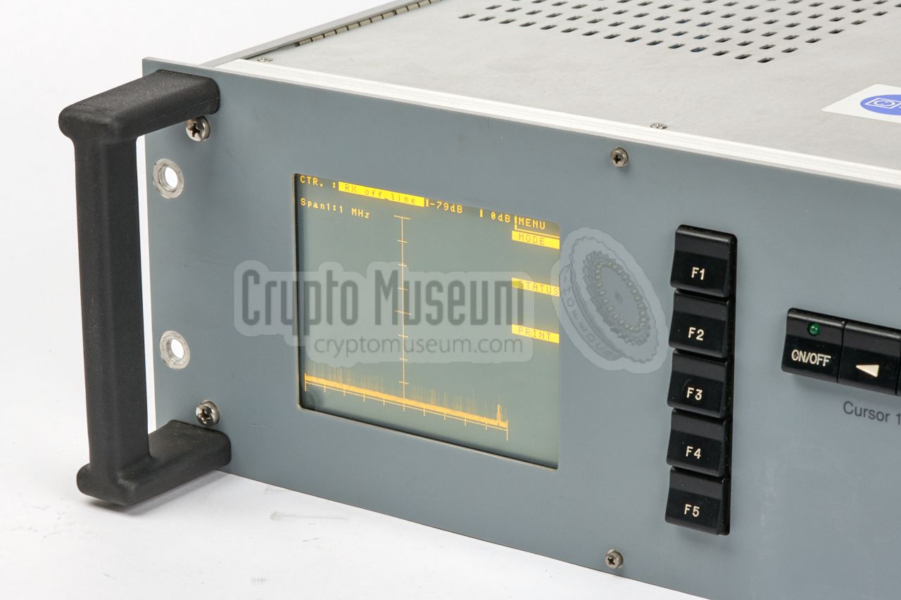
At the left is a crisp and clear Electro-Luminescent
(EL) Display 2 on which the monitored part of the spectrum is displayed.
The device takes its input from the 10.7 MHz (or 21.4 MHz) 3 IF output from
a high-end receiver and converts it to a panoramic spectrum view with a maximum
span of 1 MHz. At the rear are two separate IF inputs, allowing the
spectrum from two receivers to be watched simultanously.
|
|
|
|
The device is largely digital and is under control of an Intel 80186
microprocessor. The input is first processed in a very complex IF Interface
and then digitized, using an AD872A
A/D converter made by Analog Devices [1].
For a fast and accurate display of the monitored spectrum, with a
configurable low-pass filtering (averaging), the
device uses the so-called Fast Fourier Transform (FFT) functions of a
dedicated TMC2310 FFT processor chip
made by TRW (later: Raytheon) [2].
|
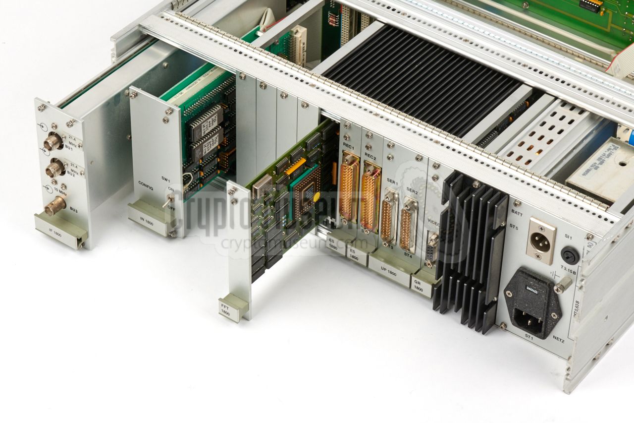
The PSG-1800 has a modular construction and consists of a wide backplane
into which a range of industrial (computer) cards are inserted.
The image on the right shows the rear side of the device, with some
of the cards partly extracted.
At the left is the IF interface that takes care of the analogue
processing of the IF signal from the (external) receivers. It is the
only card that is not plugged into the backplane, simply because it
is too large. It takes the full depth of the case and passes its
data straight to the FFT controller. It is supervised by the IF
controller unit to its right.
|
|
|
|
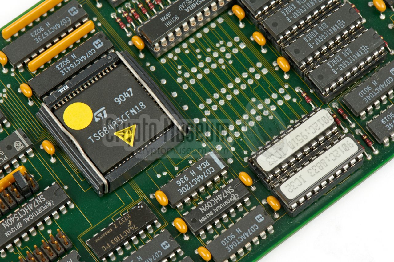
The rightmost card that is partly extracted in the image above,
is the actual FFT processor which takes care of the hard work
of doing the FFT calculations for the spectrum curve, something
that — at the time the device was developed — was not possible
in software. To the right of the FFT card are interfaces for
external storage, the 80186 processor card and the video interface.
The latter is built around a
TS68483 graphics controller
[C]. It drives the
EL display at the front panel.
|
-
Over the years, Telefunken
products were also sold under the AEG, DASA, EADS, TST
and Racoms brands.
-
Also known as a PLASMA display.
-
Option that had to be specified when ordering.
|
Below is an overview of the controls at the front panel of the
PSG-1800. At the left is the clear electro-luminescent (EL) display
that has a resolution of 320 x 256 pixels, of which 256 x 256 pixels
are used for displaying the spectrum view(s). The remaining space
is used for displaying the meaning of the function buttons (F1-F5),
which varies depending on the current menu level.
Two cursors can be displayed for reference purposes, each of which
has a set of control buttons.
All connections are at the rear of the device. At the right are the
power inputs. The device can be powered from the 220V AC mains, or
from a 12V DC source. At the left are the inputs for the IF signal
from the external receiver(s). If necesssary, the device can be
synchronised to a 10 MHz signal from a common reference.
This is particularly useful for evidence-gathering in a setup
with multiple receivers and PSG-1800 units.
When unconnected, the internal 10 MHz oscillator is used.
At the center are the CPU and the interface cards. The CPU (UP 1800)
features an 80186 CPU and two full RS-232 serial
ports (SER 1 and SER 2) for external communication and remote control.
To the left of the CPU are two interface cards for connection of
external storage (ES 1800). To the right of the CPU is the video
graphics card (GR 1800) that supplies the image for the EL display.
|
Below is the block diagram of the PSG-1800. At the far right is the
ISA bus to which al sub-units are connected. It is implemented as a
wide backplane with ten 96-pin DIN 41612 sockets. Each socket accepts
a eurocard-size (10 x 16 cm) ISA96/AT96 compatible card. In the diagram
below, the cards are shown in the same order as in the actual device.
At the top is the IF interface that accepts two IF inputs from external
receivers. It is supervised by the IF controller card, that consists
of two PCBs. The sampled output is delivered directly to
the ISA bus via a ribbon cable.
The samples are picked up by the FFT card, which then performs its
Fast Fourier Transform calculations on them. The result is then
presented on the built-in electro-luminescent display (ELD),
using an advanced video graphics card (VIDEO),
all under control of the main CPU.
|
|
Although the PSG-1800 was marketed and sold as an
AEG/Telefunken
product, it was in fact largely developed and manufactured by
ELCOM GmbH,
a small engineering company in München (Germany). For the implementation,
ELCOM used a combination of readily available industrial PC components
— such as the 80186 processor cards made by the German company ELCODATA —
and in-house developed specials, such as the
IF interface board and the FFT processor card.
|
When ELCOM
was asked in the mid-1990s by the
Dutch Radio Monitoring Service
— at the time known as HDTP-RDR
— to develop a
monitoring receiver
for intercepting and locating clandestine transmitters
(pirates), ELCOM used many parts from the PSG-1800 as the
basis for the design.
The new system became known as
PAN-2000 and was built around an existing
ICOM IC-R9000 receiver,
with a dedicated FFT processor (shown in the
image on the right) developed by ELCOM.
It is fitted in the same 3U case as the PSG-1800
and has no user controls on its black front panel.
|
|
|
|
|
|
Any links shown in red are currently unavailable.
If you like the information on this website, why not make a donation?
© Crypto Museum. Created: Sunday 02 September 2018. Last changed: Saturday, 17 May 2025 - 14:27 CET.
|
 |

|
|
|


