|
|
|
|
|

|
Telephone call analyzer
TCA-B
was a portable single-channel telephone call analyzer
for analogue subscriber telephone lines,
developed around 1979 by
Zellweger in Uster (Switzerland).
The device was intended for use by telecom operators and
for Lawful Interception (LI). It was able to
register telephone call data, such as
time and duration of a call, and the phone numbers of the calling and called parties.
|
The device measures 275 x 226 x 135 mm and weighs 3730 grams.
It was supplied in a brown carrying case with pockets for the
accessories.
It can be used on its own (stand-alone), or as part of a
lawful interception (LI) tapping room setup.
At the front is a DA-15 socket
to which the line under surveillance is connected.
When a call is initiated (incoming or outgoing), any call traffic information
(metadata) that is provided by the telecom operator, will be printed onto
the built-in thermal printer. The image on the right shows a typical single-line
setup, with break-out box.
|
|
|
|
The TCA-B was used by many telecom operators in Europe as a stand-alone device for testing and monitoring the performance of telephone lines, dial pulses,
DTMF tones,
CLI information, cost pulses, etc.
It was also used by law enforcement agencies (police) and
intelligence services,
for gathering forensic evidence in criminal investigations.
It can only register metadata and not the call content.
The device shown here, was used for many years in
one of the analogue tapping rooms of the Dutch police, until they were
replaced by digital (later: software-based) products.
|
HELP REQUIRED —
We are still looking for the operator's manual of the TCA-B, in order
to get a better understanding of the operation of the device, its
features and its applications. Please help us to expand this page by
providing additional information. Reports from former users and
eyewitnesses are also welcome. ➤ Contact us
- TCA-A
This model is believed to have been introduced around 1970
for use on exchanges with impulse dialling and limited signalling.
The exact details are currently unknown.
- TCA-B
This model is believed to have been introduced around 1979.
It is programmed by means of a rotary selector (MODE),
a set of 8 numeric thumbwheel selectors and an execute button.
This is the model that is described on this page.
- TCA-C
This model is believed to have been introduced around 1990.
The thumbwheels of the TCA-B have been replaced by a numeric LED display
and a 16-button telephone keypad, allowing easier input of the initial
settings. See this image
from Nordlandsmuseet [2].
|
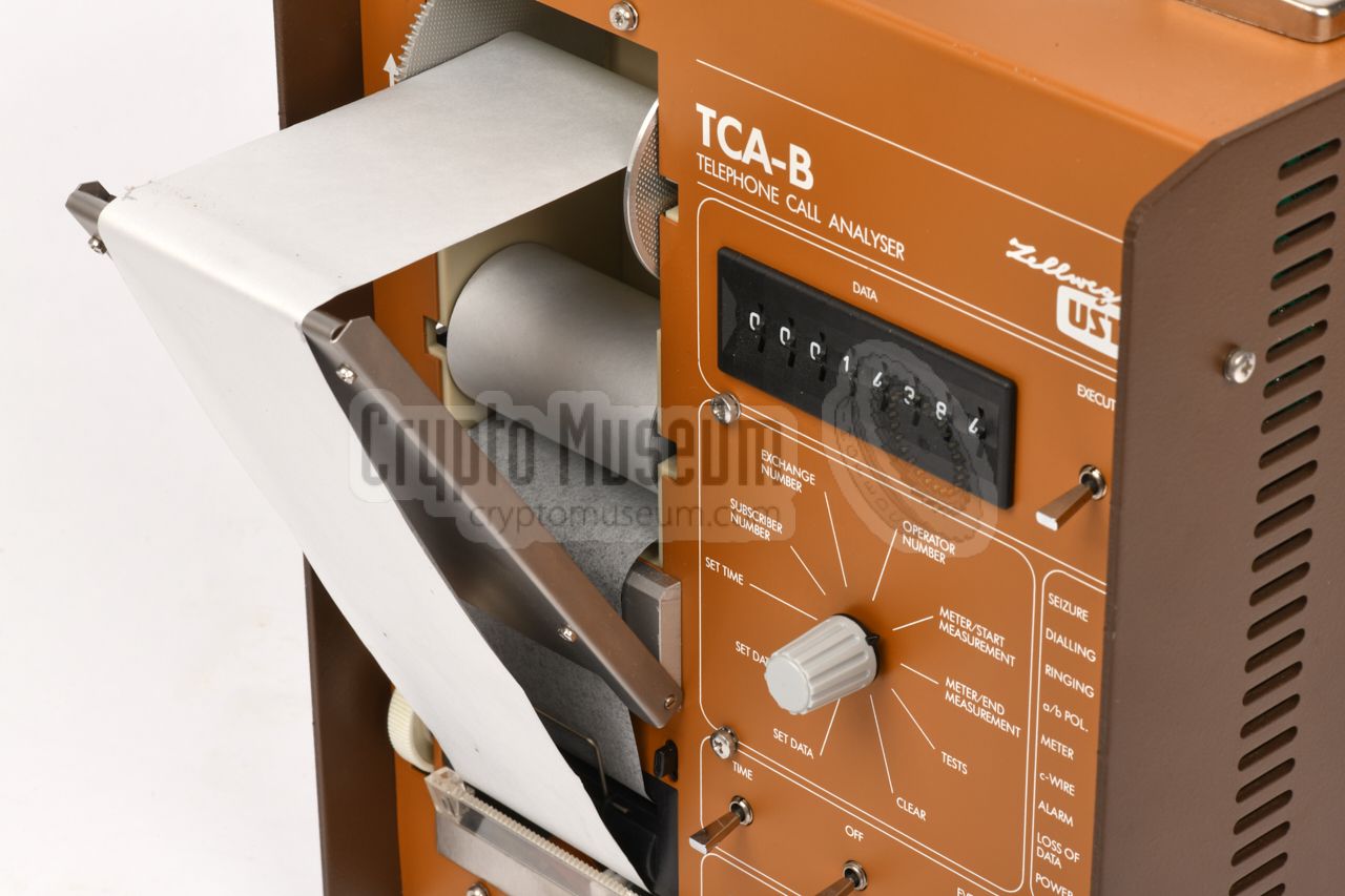
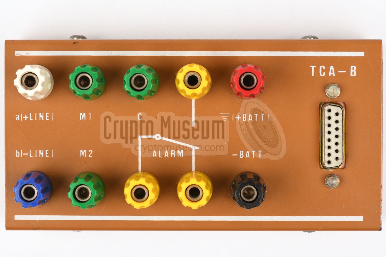
The diagram below gives a quick overview of the control and connections
on the front panel
of the TCA-B. The device is connected to the analogue
subscriber line (under surveillance) and a 48V DC power supply, via the
15-way DA-15 socket
at the bottom right. The controls on the front panel
are enabled by setting the key-operated switch
at the bottom centre to the
ENABLE position. This allows the date, time, operator number, exchange number,
etc. to be programmed.
Programming is done by setting the
MODE selector at the centre to the
desired position, entering the required data on the
thumbwheels at the top,
and pushing the EXECUTE switch upwards. Once all data has been entered,
the key is returned to the LOCK position, so that no data can be altered
anymore. The line under surveillance will now be monitored and the
LEDs along the right side of the front panel,
will show the current status and
any alarms. As soon as an incoming or outgoing call is initiated, the
metadata will be printed on the thermal printer at the left.
|
In most countries, lawful interception (tapping)
is restricted by a complex set of laws. For this reason, the TCA-B only
registers the metadata and not the call content.
For recording the call content, a separate system had to be used.
In the Netherlands, the TCA-B was used in the analogue tapping rooms of the
police and the intelligence services.
A tyical setup of the 1980s is the
ATR shown in the image on the right.
➤ More information
|
|
|
|
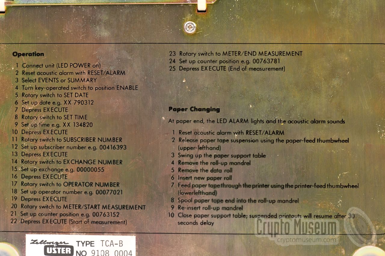
The full operating instructions are printed in the user manual, which is
unfortunately missing from the device in our collection. Luckily, they are
also printed on the metal back panel
of the device, along with instructions
on how to replace the thermal paper. A quick summary:
|
- Connect unit to 48V DC power (LED POWER on)
- Reset acoustic alarm (press RESET ALARM)
- Select EVENTS or SUMMARY
- Set key to ENABLE
- Set MODE selector to SET DATE
- Enter date (e.g. 19790312) and press EXECUTE
- Set MODE selector to SET TIME
- Enter time (e.g. xx134820) and press EXECUTE
- Set MODE selector to SUBSCRIBER NUMBER
- Enter subscriber number (e.g. 00416393) and press EXECUTE
- Set MODE selector to EXCHANGE NUMBER
- Enter the exchange ID number (e.g. 00000055) and press EXECUTE
- Set MODE selector to OPERATOR NUMBER
- Enter the operator ID number (e.g. 00077021) and press EXECUTE
- Set MODE selector to METER/START MEASUREMENT
- Enter counter position (e.g. 00763152) and press EXECUTE
- Set MODE selector to METER/END MEASUREMENT
- Enter counter position (e.g. 00763781) and press EXECUTE
|
|
In addition to the external settings described above — which can be entered
by the user — there are a number of internal settings, which allow the
device to be customised for a specific protocol, country, exchange or
application. This requires setting some straps (jumpers), altering
removable resistors and ultimately swapping a Programmable Read-Only
Memory (PROM) on the CPU board.
|
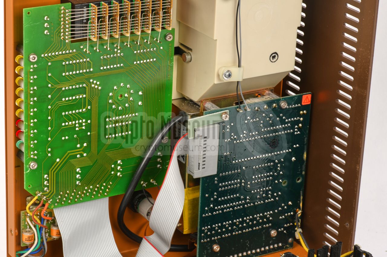
The internal settings are located behind a hinged metal panel at the rear
side of the device, and requires loosening one screw.
The instructions are printed on the inside of the lid
as shown here. Behind the panel is also a socket (embedded in the PCB) marked
Interface Connector. Although the pupose of this socket it currently
unknown, it allowed the system to be expanded later.
|
The TCA-B was supplied in a dark brown nylon storage case, like
the one shown in the image on the right. The largest compartment takes
the device, of which the grip protrudes the lid.
At the front are two pockets for the break-out box,
the cables,
spare printer rolls, etc.
|
|
|
The TCA-B is a fully autonomous device that can interpret the signalling data
from the telecom provider – sent by means of AFSK
or DTMF tones before the call is answered – as well as
the DTMF tones of a push-button telephone and the pulses of an old dial
telephone, and print them onto the thermal printer at the left.
The device is powered by 48V DC – which was a common DC voltage in any
analogue telephone exchange – via the break-out box below.
|
|
|
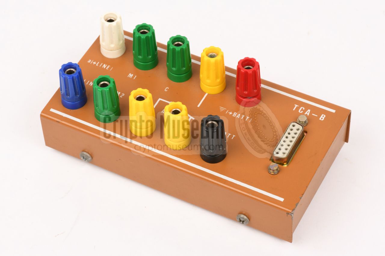
All connections to and from the TCA-B,incuding the external power supply,
are via the DA-15/P
socket at the bottom right of the front panel.
In a stand-alone setup, the break-out box shown in the image on the right,
should be connected to this socket, using the supplied 15-way cable.
The breakout box has a 10 banana-sockets, for connection of the
external 48V power supply, the line under surveillance and for controlling
the motor of a tape recorder.
Furthermore, it provides three isolated alarm (relay) contacts.
|
|
|
All connections to and from the TCA-B, incuding the external power supply,
are via the DA-15 socket
at the bottom right of the front panel.
The 15-way cable shown in the image on the right was supplied with the set
and was usualy stowed in the right pocket of the carrying case.
The cable can be used to connect the TCA-B to the break-out box
shown above, or to other equipment, such as a
police tapping room setup.
|
|
|
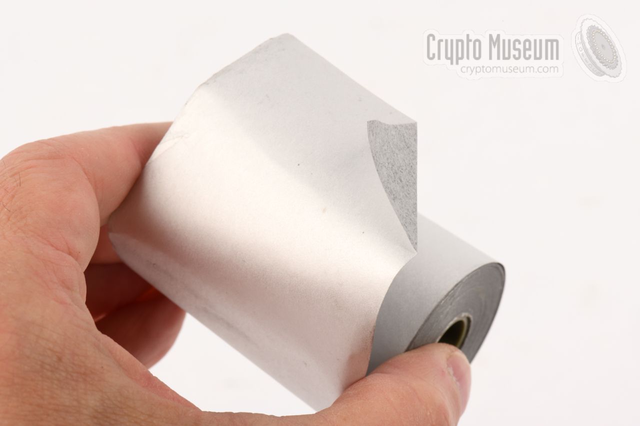
The TCA-B has a built-in thermal printer that can not be used with
regular paper from, say, a calculator or a cash register. Instead
it needs thermochromic paper, that changes colour
when it is heated by the print head [3].
Although this was a standard type and size of printing paper at the time
the TCA-B was sold, it is far less common today. Some types of thermal
paper were even abandonned under pressure of environmental activists,
because of unconfirmed health issues [3].
|
|
|
|
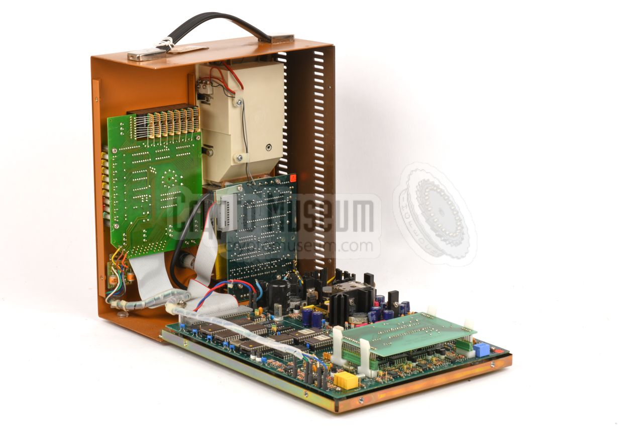
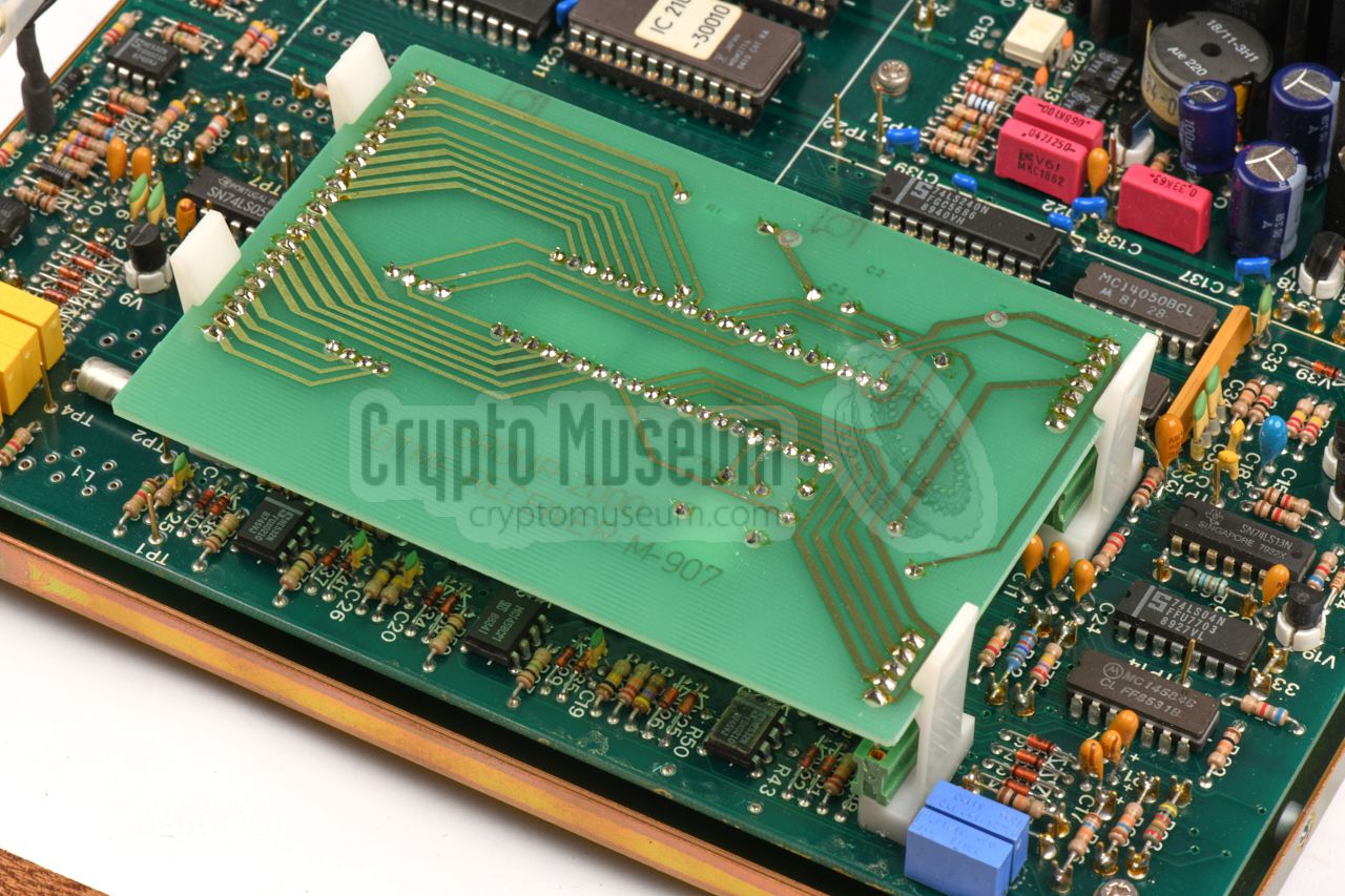
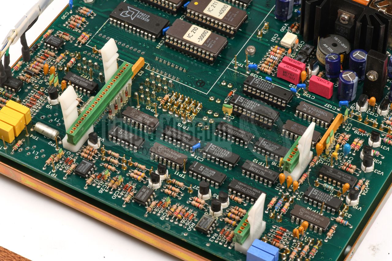
The device is made of high quality passivated steel, sprayed in two colours:
orange and brown, with a fine eye for detail and precision. The interior can
be accessed by removing 6 screws along the edges of the rear panel: two at
the orange top and two at each of the brown side panels.
|
|
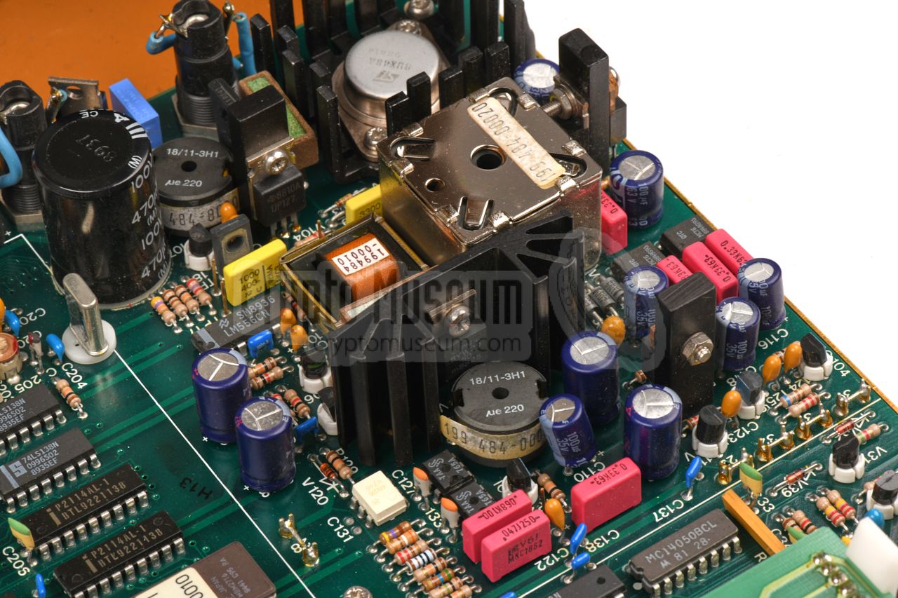
Close to the upper edge of the CPU board is a
small daughter card with
the DTMF receiver. It is not made by Zellweger, but was provided
as plug-in solution by Dutch ICT security company Group 2000, who was also
the supplier of a number of tapping rooms of the Dutch police.
The board holds a
single hybrid circuit on a ceramic substrate - in
the shape of a 40-pin Integrated Circuit (IC) - with a complete DTMF decoder, made in 1984 by
Teltone Corporation (USA) [a].
|
Supplier Zellweger, Uster (later: BlueCom) Order Nr. AZH 198.056-0000 Part Nr. TVA-B Power 48V DC
|
- Line (+)
- M1
- C
- not connected
- Alarm (common)
- Battery (+) 48V
- Battery (+) 48V
- Battery (+) 48V
- Line (-)
- M2
- not connected
- Alarm (normally open)
- Alarm (normally closed)
- Battery (-)
- Battery (-)
|
|
|
AFSK
|
|
Audio Frequency Shift Keying
System in which two unrelated audio tones – commonly called mark
and space – are used to represent the digital values '0' and '1'
in order to send digital data over an analogue medium. AFSK is typically used
with MODEMs. In telephony, it was also used for passing signalling data
(such as caller ID) over a telephone line.
➤ Wikipedia
|
|
DTMF
|
|
Dual-Tone Multi-Frequency
Telecommunications signalling system, used to pass numbers over
analogue telephone lines, using voice-band (dual) tones. In the US
also known under the Bell Systems trademark Touch-Tone.
Typically used in (analogue) push-button dialling telephones.
➤ Wikipedia
|
|
|
|
Any links shown in red are currently unavailable.
If you like the information on this website, why not make a donation?
© Crypto Museum. Created: Friday 14 June 2019. Last changed: Wednesday, 05 November 2025 - 12:03 CET.
|
 |

|
|
|


