|
|
|
|
|

|
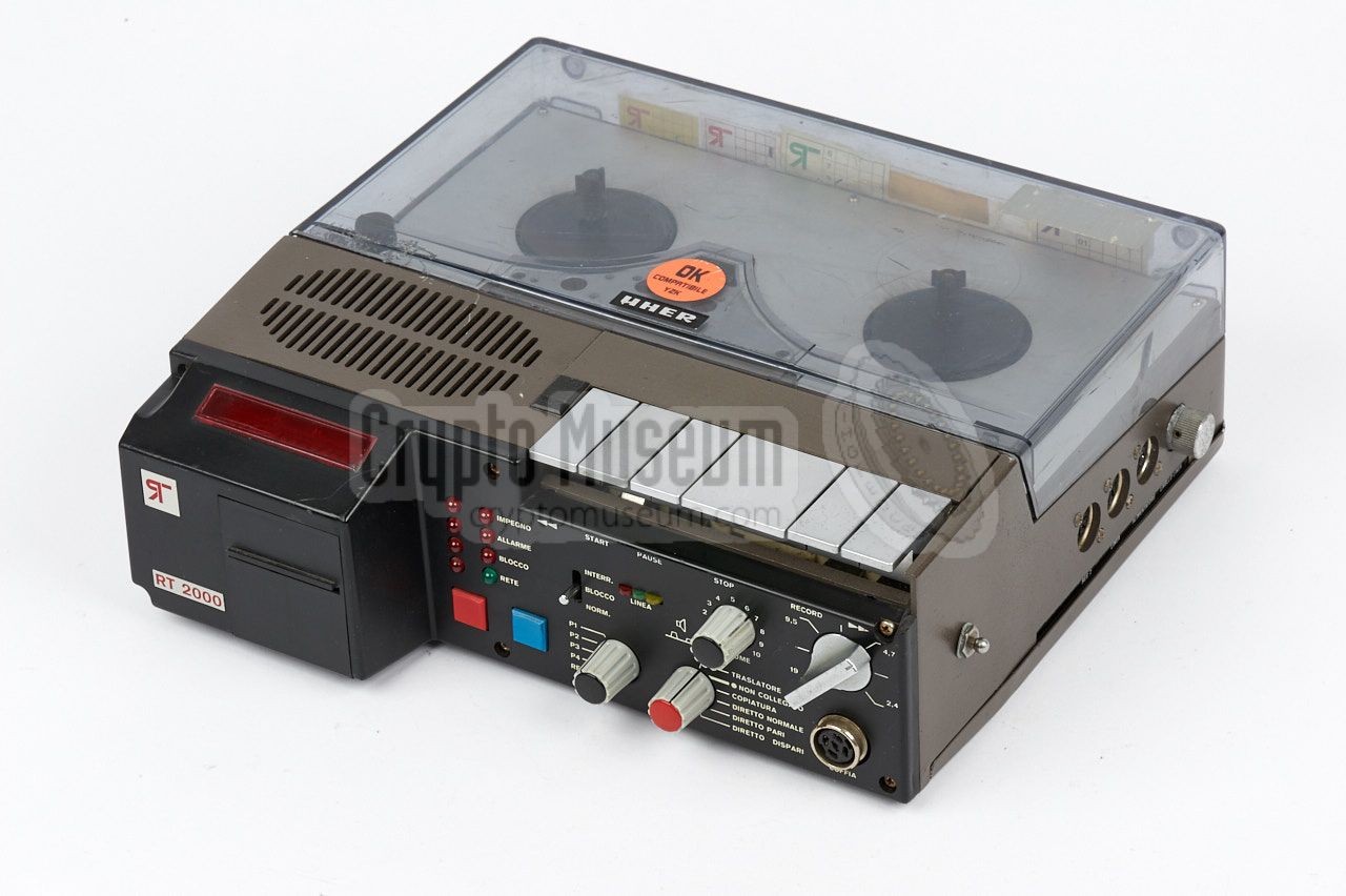
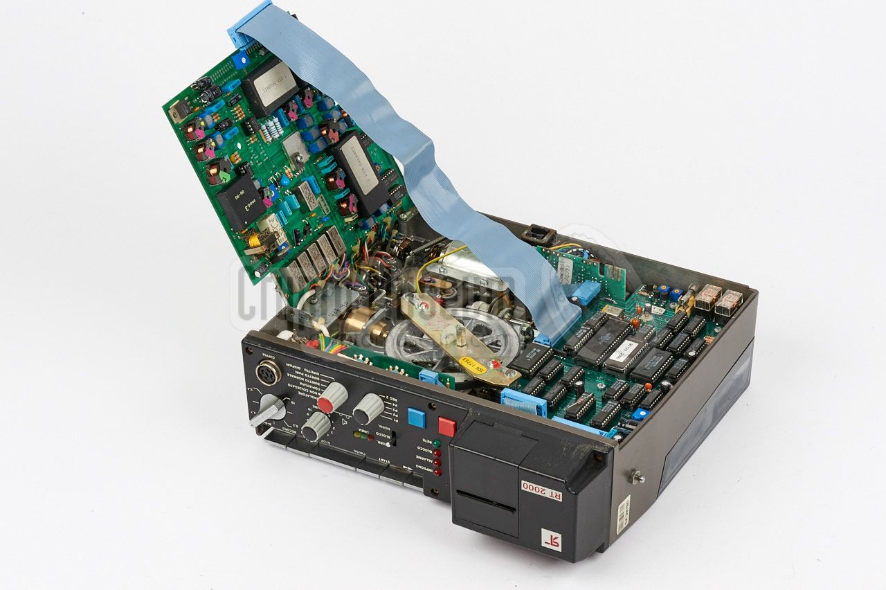
The image on the right shows an example of a typical RT-2000 [1].
The original UHER open reel recorder on which the device is based can still
be recognised.
The recorder's original front panel has been removed by Trevisan
and is replaced by different controls and a series of indicators.
More importantly, a small printer was added at the front left,
with a 14-digit LED display at the top surface. The device can record up
to 4 audio channels simultaneously and prints the relevant information, such as
time and date, and the dialled telephone number, on the ticket printer.
|
|
|
As the recorder was used
by law enforcement agencies during criminal investigations, the printer
provided the necessary legal evidence by logging the data.
The RT-2000 was developed in 1982 and was in production until 1988. The device
shown here was produced in 1986. The RT-2000 was succeeded in 1985 by the
RT-5000 and eventually in 1995 by the fully
digital RT-6000
[2].
|
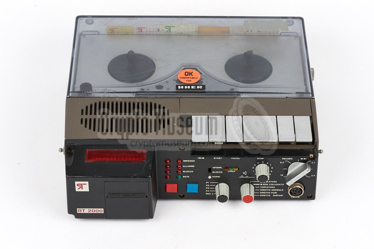
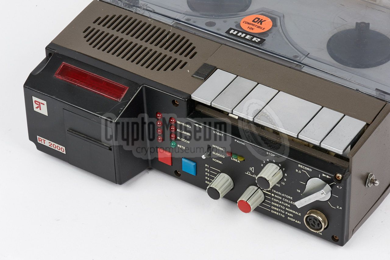
The diagram below shows the position and function of the various controls
and connections of the RT-2000. The standard features of the UHER 4400 on
which the record is based, are still available at the usual position.
The six standard control buttons are the top front right.
The front panel
has been replaced completely and now features a printer and a display inside
a bulge at the left. The speed selector is at the top right, but all other
controls are different from the 4400.
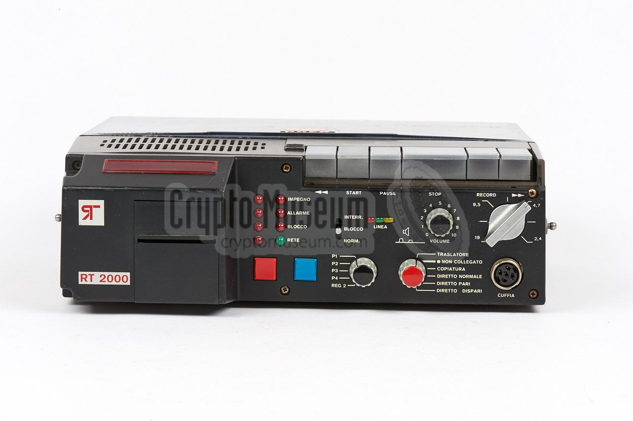
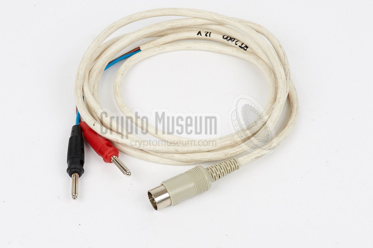
All connections are at the right. There are three DIN sockets for line input,
line output and 12V DC power input.
Please note that the pinout of these
sockets is different from the ones on the original UHER 4400.
To the right of the three DIN sockets is the line level adjustment knob.
|
|
The interior of the RT-2000 can be accessed by rotating two bolts at the
bottom panel, after which the panel can be removed. This reveals
two printed circuit board (PCBs)
that are interconnected by means of a
40-wire blue flatcable. The top PCB is held in place by a single screw.
|
After removing this screw, the upper PCB can be hinged towards the left,
as shown in the image on the right. This reveals the
unaltered UHER 4400 mechanism,
which is the only part that has been left intact from the original
UHER design.
All other parts, including the power section, the motor driver, the audio
board and the digital control board, have been completely redesigned by
Trevisan. The hinged audio board
contains four purpose-built circuit
blocks, of which the function is currently unknown. They most likely
contain a potted PCB with several components.
|
|
|
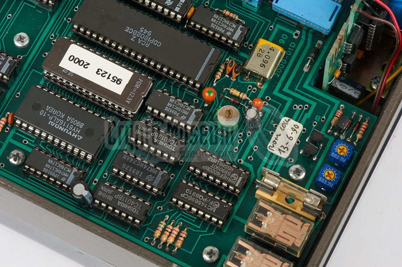
The lower PCB
(i.e. the PCB that is mounted to the right of the mechanism),
is the control board, which is built around an
RCA CDP1802 8-bit microprocessor
[4], with external RAM and EPROM. A small vertically mounted PCB at the
rear centre, hold the motor driving circuit. All circuits are powered by
12V DC, which should be supplied via the
rearmost DIN socket at the right side.
|
|
The RT-2000 has a series of DIN connectors at the right side, of which the
rightmost one (i.e. the one closed to the rear of the device) is the
power socket. Note that the pinout of these sockets is different from the
ones on the original UHER 4400 recorder.
|
|
The rightmost socket is for the connection of a PSU.
On the Italian version of the RT-2000 it is marked as ALIMENTATORE.
On the original UHER recorder it was marked with a triangle.
|
|
Note that this connection is different from the original accessory
socket of the UHER 4400 Report recorder.
The RT-2000 is powered by a +12V DC source, whilst the UHER recorders
needed -7.5V (the UHER had + connected to ground). On the RT-2000, the (-)
terminal is connected to ground.
|
- UHER, UHER 4000/4200/4400 Report Monitor, Service Handbook
Without circuit diagrams. Date unknown. 1
- UHER, UHER 4000 Report-L, Model 4200 and 4400 Supplement
With full circuit diagram. Date unknown. 1
- UHER, UHER 4000 Report-L and Report-S, Parts List
Date unknown. 1
- UHER, UHER 4000 Report-L, Circuit Diagram
Date unknown. 1
- UHER, UHER 4000/4200/4400 Report-IC and Stereo IC, Service Manual
Complete with circuit diagrams. Date unknown. 1
- UHER, UHER 4000 Report IC, Circuit Diagram
Date unknown. 1
|
|
|
|
Any links shown in red are currently unavailable.
If you like the information on this website, why not make a donation?
© Crypto Museum. Created: Saturday 24 December 2016. Last changed: Wednesday, 24 July 2019 - 07:36 CET.
|
 |

|
|
|


