|
|
|
|
|

|
Differential RF Detector
Delta-V ECM is a handheld differential
detector for
covert listening devices (bugs),
introduced in 1991 by Audiotel in Corby (UK)
as the successor to the original Delta-V.
It allows quick scanning of rooms, people, vehicles and other objects,
by brushing over them.
Although the device was often used alongside existing
Scanlock receivers,
it can also be used as a stand-alone device.
|
Delta-V ECM is an improved version of Delta-V,
and is housed in a slightly larger enclosure. the two antennas have been placed
further apart and have more robust SMA sockets. Furthermore, the device has
an improved dynamic range and a better frequency response, uniform
to 6.5 GHz.
In use, Delta-V ECM produces a ticking sound, much like a Geiger counter
does when sensing radioactivity. When getting closer to the bug,
the ticking becomes faster. Right on top of the bug, the tone will be
continuous. The volume of the tone can be adjusted with a knob at the bottom.
|
|
|
The device measures the difference in signal strength between the two antennas.
When sweeping a room, any signal from a transmitter outside the room, e.g. a
strong local radio station, or a taxi passing by, is likely to be received
equally strong on both antennas. A rogue transmitter close to the device
however, such as a bug hidden in the room, will produce a different field
strength on each of the antennas, especially when the device is held within the
nearfield of the transmitter.
Delta-V
and it successors have been on the market for well over 30 years,
providing an easy to use and cost-effective means to
search objects for bugs. Despite its simple appearance, it is
a powerful and very effective tool that should be part of the basic
configuration of every sweep team.
Delta-V ECM was succeeded in the mid-2000s by the similar looking
Delta-V Advanced,
which has the added capability of detecting
burst transmissions
in the 50 MHz to 15 GHz range.
|
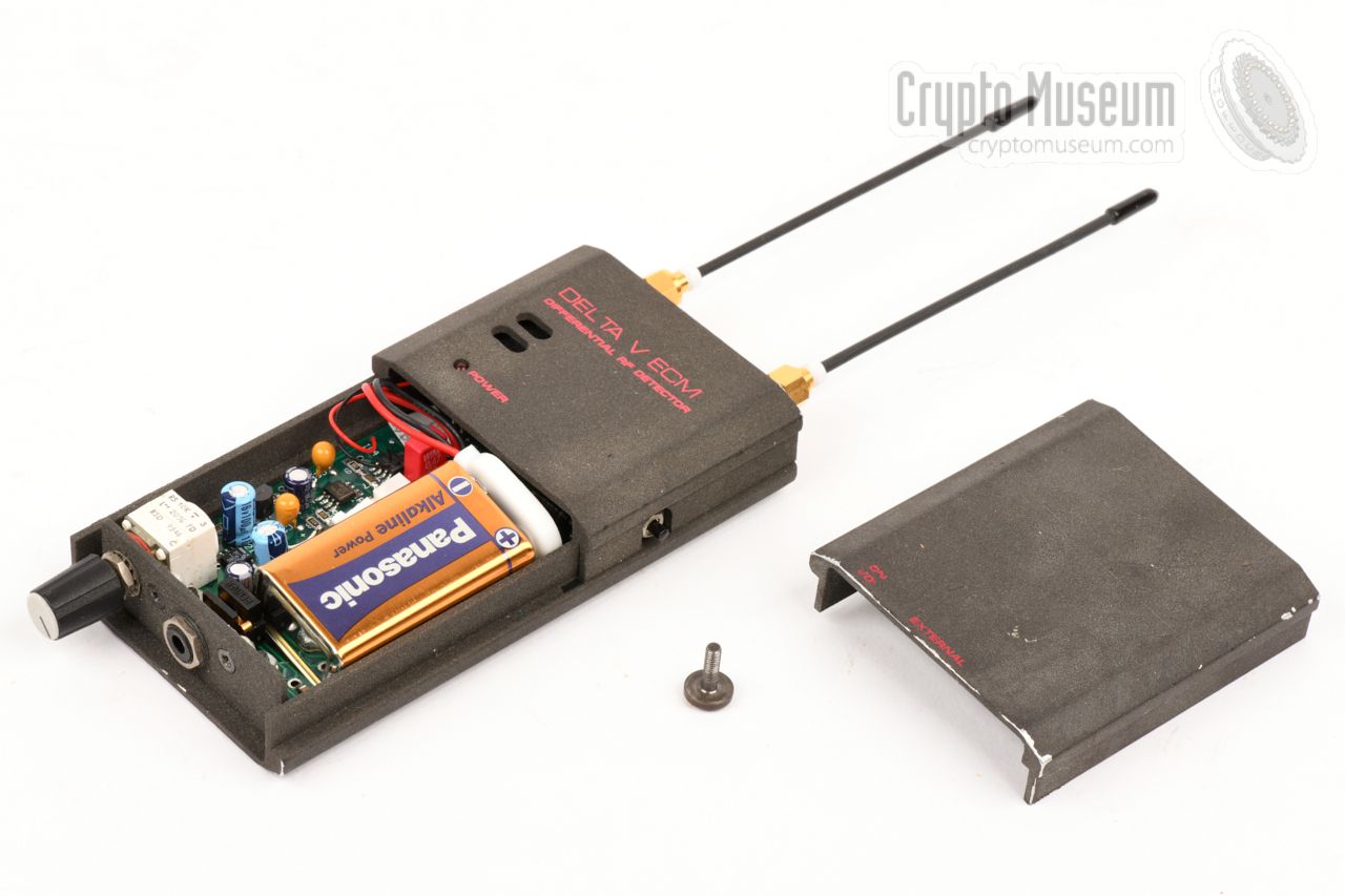
The diagram below provides a quick overview of the controls and connections
on the body of the Delta-V ECM. The device is constructed in such a way that
it can easily be carried in one hand. At the top are two SMA antenna sockets
on which the supplied rigid antennas should be installed.
At the bottom is a volume knob, which also acts as the ON/OFF switch.
When turned fully anti-clockwise, the device is OFF. Power is provided by
a standard 9V block battery that should be installed behind the removable
panel at the front. Approx. 10 seconds after switching ON, the device is
ready fo use, and a clicking sound will indicate the presence of any
RF signals. The sound is produced by the built-in speaker or, when
connected, through the (optional) earpiece.
When (too) close to an RF source, the sensitivity can be reduced
by pressing the push-button at the side.
It is also possible to use the detector as a regular field strength indicator
by using just one antenna and leaving the other SMA socket
empty (or terminated).
This makes the device more sensitive to weak radio signals,
but looses the advantage of cancelling out nearby radio stations.
|
The principle of operation is illustrated in the drawing below.
The strong broadcast transmitter
is relatively far away.
As a result, the signals that hit the antennas
will practically be equally strong (or weak).
The bug on the other hand,
is relatively close to the detector and is therefore likely to cause a
different field strength at each of the antennas and hence produce a stronger
reading.
The larger the difference,
the faster the clicking sound produced by the detector.
When held very close to the transmitter, the devices produces
a continuous tone. An attenuator push-button, on the right side panel,
allows the device to
be used in close proximity of very strong radio signals.
|
|
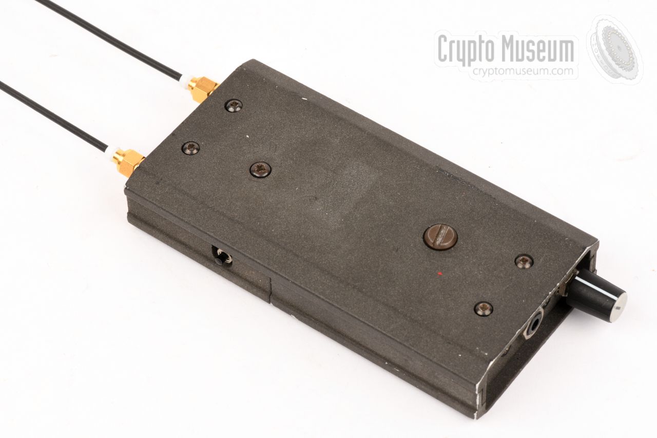
Delta-V ECM is housed in an extruded aluminium enclosure that is
sprayed in a fine grey texture, similar to other members of the
ECM range.
It measures 122 x 62 x 22 mm and weighs just 238 grams, incuding the battery
and the antennas, making it the ideal companion for a site survey.
|
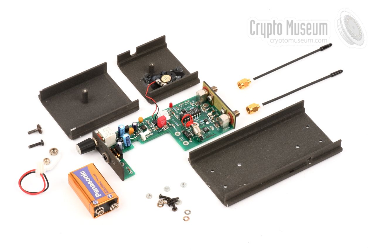
The interior can be accessed by releasing the
large battery cover bolt at
the rear of the device,
and one large phillips screw – also at the rear –
after which both the battery cover and the front panel can be removed.
In order to remove the PCB from the enclosure, the remaining four screws
at the rear panel should also be removed.
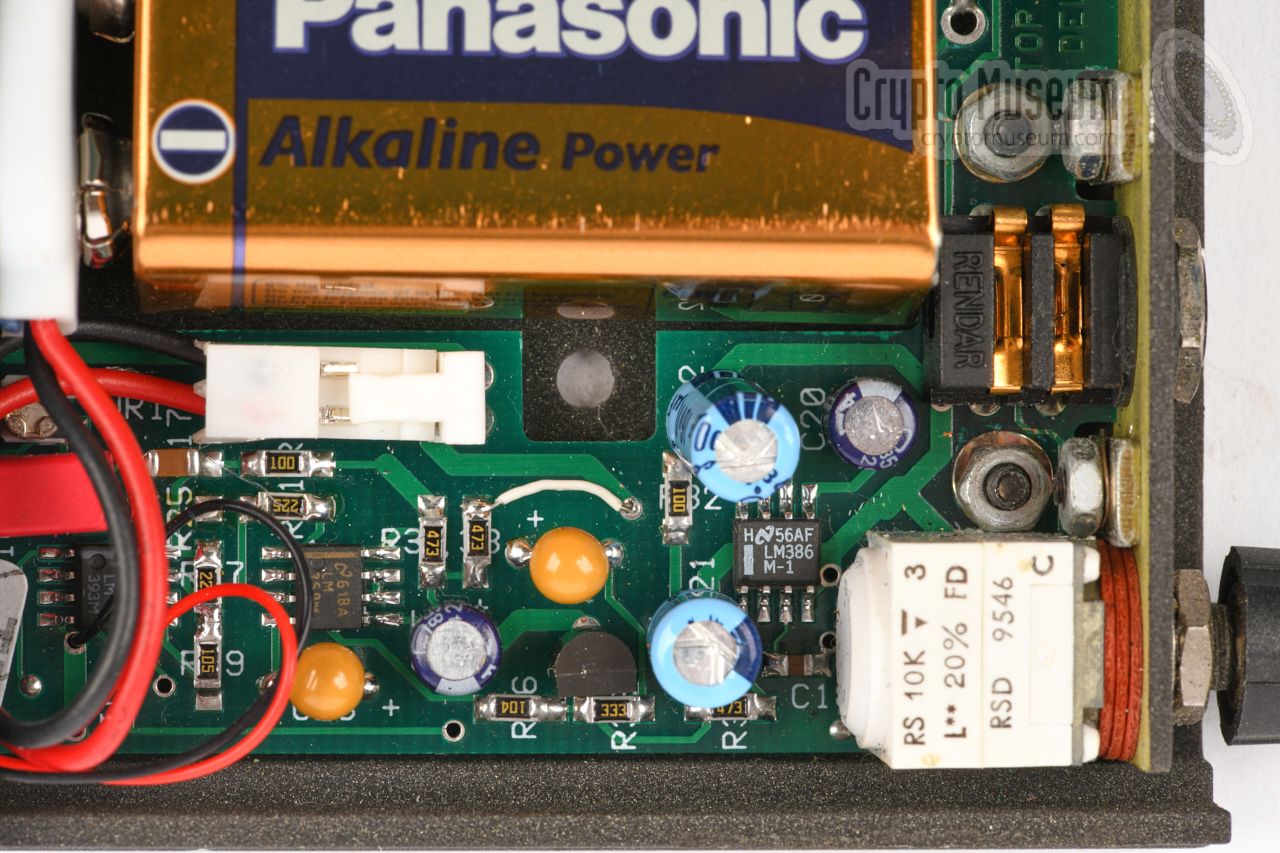
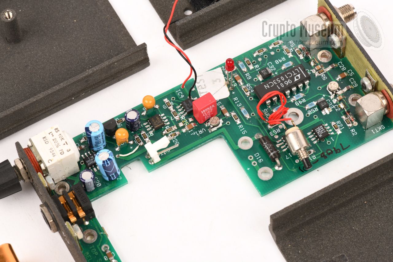
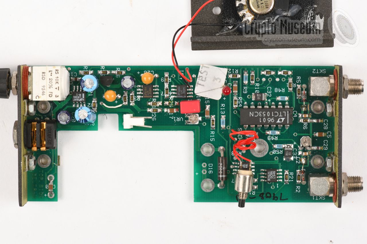
The image on the right shows the part of the PCB that contains the
tone generator and the audio amplifier. It becomes visible when the
battery lid is removed
and produces the clicking sound that indicates
the presence of a nearby radio signal.
|
|
|
|
The double-sided PCB has components on both sides,
although most parts are located
at the top,
which is the side that is visible when the device is
first opened. The bottom side
is fitted with Surface Mount Devices (SMDs)
only. The PCB has a large cut-out to accomodate the 9V battery.
|
Below is the block diagram of the device. At the left are the antenna inputs
(ANT 1 & ANT 2),
followed by two (matched) schottky barrier diode detectors, of which the outputs
are fed to a low-noise
wide-dynamic-range differential logarithmic DC amplifier with
offset cancelling and automatic drift compensation. The signal is amplified
in a second logarithmic amplifier and then rectified, to produce a DC
voltage proportional to the strength of the differential input signal.
The proportional DC level from the rectifier drives a Geiger-type click
generator that produces a rising tone when getting closer to the transmitter.
The audio signal from the click generator is amplified and then delivered to
the internal speaker (or alternatively to the external earphones).
|
Frequency ± 5dB, 10 MHz to >6.5 GHz Sensitivity -53 dBm Dynamic range >50dB, typically -52dBm to +5dBm at 1GHz Power source 9V alkaline PP3 (24 hours of continuous operation) Size 122 x 62 x 22 mm Weight 238 g (including battery and antennas)
|
|
|
|
Any links shown in red are currently unavailable.
If you like the information on this website, why not make a donation?
© Crypto Museum. Created: Sunday 06 October 2019. Last changed: Wednesday, 05 November 2025 - 12:01 CET.
|
 |

|
|
|