|
|
|
|
|

|
|
NRP RCD
Field strength indicator with frequency counter
NRP-FS, also known as model 88211, is a handheld
field-strength indicator, 1 developed in 1983
by the Radio Monitoring Service (RCD) of
the Netherlands, and manufactured at the
Dutch Radar Laboratory (NRP)
in Noordwijk (Netherlands).
It has a built-in frequency counter and was used by the RCD
as a law-enforcement tool when locating clandestine transmissions (pirates),
commonly alongside the PAN-1000 intercept receiver.
It was also used by the Dutch Foreign Office (BuZa).
|
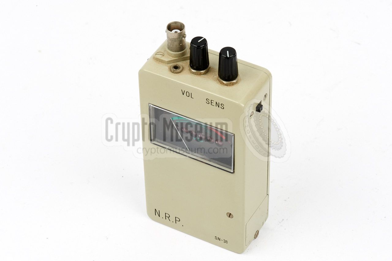
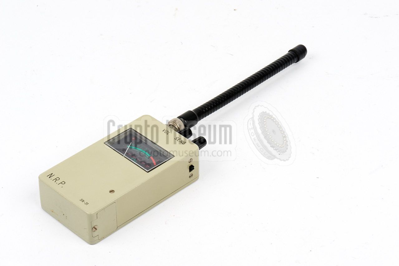
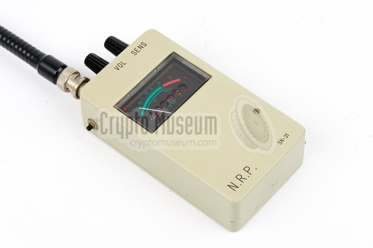
The device is housed in a small beige-painted BIM box,
and measures 11 x 6 x 3 cm (without the controls). It is intended
for uncalibrated relative field-strength measurements in the
10 to 500 MHz frequency range, with the optimum sensitivity between
80 and 180 MHz. The rightmost knob at the top is used for
the adjustment.
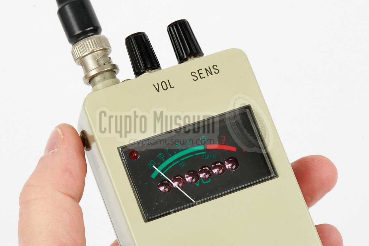
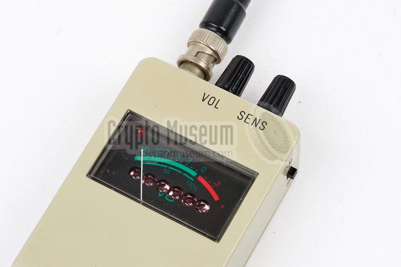
At the heart of the front panel is a standard VU meter which
was commonly found on the audio equipment of the era. Below the
scale however, six holes have been drilled through which the
lenses of an HP 6-digit LED display protrude.
|
|
|
|
The LED display is used for the built-in frequency counter.
The device is turned ON with a small slide switch at the right top.
When it is ON, the internal frequency counter can be enabled by
pressing a small push-button at the left. It order to save battery power,
the counter is disabled when the push-button is released.
The frequency counter can be used reliably from 10-550 MHz.
|
Outside this range, the counter's sensitivity rapidly decreases with
approx. 6dB per octave.
The optimum sensitivity is at 100 MHz (3 metre band), which confirms that
its main purpose was for finding clandestine radio stations (pirates)
operating in the 88-108 MHz broadcast band.
The NRP-FS was introduced with the
Dutch Monitoring Service (RCD)
around 1983 alongside the purpose-built
PAN-1000 intercept receiver.
It was commonly used to determine the exact location from which a
clandestine transmission originated, and often led directly to the source.
|
|
|
In addition, it helped the law enforcement officers to determine
the exact frequency of a mobile radio station, whilst driving around.
If they saw someone operating a mobile radio, all
they had to do was press the button in order to determine the frequency.
The PAN-1000 was then adjusted to the same frequency, after
which the officer could establish the legality of the transmission.
The device was also used by the Dutch Foreign Office as one of the tools
to check a meeting room or an embassy for
covert listening devices (bugs).
At the time, most professional bugs used frequencies between 100 and 400 MHz
and would often cause a frequency counter to lock-on.
|
-
As the field-strength meter was custom-built in small quantities
for one or two customers only, it was not given an official name
or product designator. We therefore refer to this device as the NRP-FS.
|
The diagram below shows the various features of the NRP field-strength
indicator. It is powered by a standard commercial 9V block battery
that is installed behind a lid at the bottom of the right side. When the
unit is turned ON, a faint red LED lights up in the top left
corner of the meter.
When locating a transmitter, small increases in field-strength can be
detected by observing the needle of the meter. Alternatively, a small
earpiece can be connected to the 2.5 mm jack socket at the top panel,
in order to obtain an acoustic indication of the field-strength.
When the signal strength increases, the pitch of the indicator tone
also increases. When the reading is at its maximum, the tone switches
OFF and the sensitivity (SENS) must be lowered to get a tone again.
|
It has meanwhile come to light that there is a version of the NRP
field strength indicator with an
extra slide switch at the front panel,
just above the meter. Setting this switch to the rightmost position,
allows the device to measure frequencies up to 1 GHz. In that position,
only 5 of the available 6 digits are used. This option was used for
detecting and finding illegal cell phones inside buildings,
which were commonly operated in the 890-930 MHz frequency band [3].
This feature is shown in red in the diagram above.
|
Device Field-strength indicator with frequency counter Purpose Locating clandestine transmissions Model 88211 Developer RCD Manufacturer NRP Frequency 15 - 550 MHz (some versions: 1 GHz) Optimum 100 MHz Indicator VDU meter Audio 2.5 mm jack for earphone Power 9V (internal battery) Resolution 10 kHz Dimensions ? Weight ? Quantity 50
|
- Anonymous, NRP field strength indicator - THANKS !
January 2017.
- Dan de Bruijn, Image of NRP field strength indicator S/N 15
Personal correspondence, December 2020.
- Anonymous former user, personal correspondence
October 2024.
|
|
|
|
Any links shown in red are currently unavailable.
If you like the information on this website, why not make a donation?
© Crypto Museum. Created: Saturday 28 January 2017. Last changed: Friday, 01 November 2024 - 09:47 CET.
|
 |

|
|
|


![NRP-FS with extra switch. Photograph kindly supplied by Dan De Bruijn [2].](img/nrp_fs_15.jpg)